Week 3 - 2D meshing for sheet metal
AIM
To disintergrate the given 3D model to 2D model with rectified quaity critria.
PROCEDURE
To disintergrate the model with following steps
- Geometry cleanup
- Midsurfacing
- Meshing
1. GEOMETRY CLEANUP
The first and foremost process in process is geometry cleaning.
Geometry cleaning is the process of fixing geometry error such as triple cons, single cons, cracks and so on.
Before geometry checks setup property for each subpart and done a geometry resolution.
TOPO-----> AUXILIARIES ----> FINE
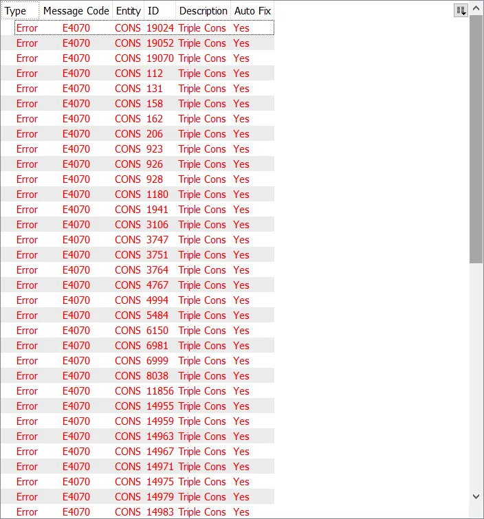
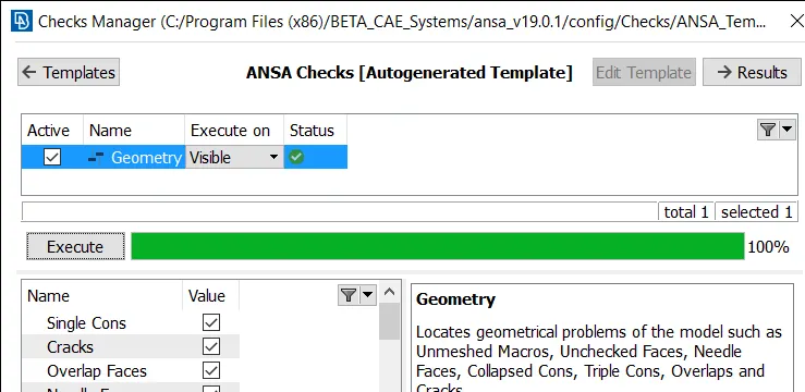
After all refining process go forr geometry check, it shows where are the error occur by click the error icon we found error on model and fix it by using several commands.
TOPO ----> CONS ----> RELEASE
TOPO ----> HOT POINTS ----> INSERET / DELETE
After all geometry checks fix then go for topology activity to associate each faces.
TOPO ----> FACES ----> TOPO
2. MIDSURFACING
After executing of geometry cleaning process then go for mid surfacing process.
It is the process of extracting the middle surface.
Middle surface is extracted by offsetting the faces before offset orientation as to be done its looks yellow and gray.
After extracted the midplane looks red edges.
After midplane achieve assigning of property to the plane.
At last changing ENT to PID and the midplane is ready.
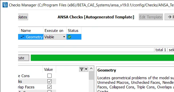
Again go for geometry checks this time by switching off singlecons option.
TOPO ----> FACES ----> OFFSET
TOPO ----> FACES ----> ORIENT
TOPO ----> FACES ----> TOPO
3. MESHING
After the midsurface extracting process then go for meshing process before entering into mesh operation some meshing parameter as to set fo execution.
Before meshing mesh element lenght as to choose.
MESH ----> PERIMETRE ----> LENGTH
To check length reviewing the model area by area if any inconsistance remove hotpoints and change length as per area we want.
Make sure that all the holes in the model ahould have even number of edges, if not it can be change by num add /less command.
MESH ----> PERIMETRE ----> NUM ADD/LESS
Defeaturing process is the process of cutting the middle of the fillet region to regain the shape without loosing volume of the model.
MESH ----> MACROS ----> CUT
At last before meshing setup of quality criteria parametre for model by clicking F11 and change the criteria as per requriments,parameter presentation, type of mesh, element type and order of element.
Setup mesh parameter with min and max lenght parameter.
Meshing process mesh generation area by area by using best algorithm.
MESH ----> MESH GENERATION ----> BEST
Number of trias, quad and quality criteria on / off is available by selecting hidden object command.
Improving the quality by adjusting the mesh using mesh impovement tools.
MESH ----> ELEMENT ----> SPLIT
MESH ----> SHELL MESH ----> RECONSTRUCT
MESH ----> SHELL MESH ----> SMOOTH
Two trais should not faces opposite to each other and trias should not originate from the edge.
Meshing element nodes are the paste by manually by fixing quality issue.
By switching on bound command it shows cracks and any other quality issues.
By element releasing the meshing for not changes in cad model.
MESH ----> ELEMENT ----> RELEASE
Final step in the meshing process is transform to desk by switching on FE and CAD model.