Week 6 - Creating connection for Rear door
Aim: To do connections wherever required in the side door geometry.
Procedure:
- Import the FE model.
- Check for bolt,c-bush,spot weld, seam weld and hinge connections in the FE model.
- Connections are done to ensure force transmission during simulation.
- Bolt Connection: Check for parallel holes in the FE model.
- Create a COG point across the hole.
- Convert the COG point to 3D point to bolt using convert option.
- Select the bolt using connection manager.
- Select the PID's in connection manager tab
- Select the FE representation as bolt and give appropriate search distance
- Apply and realise the bolt, do the above procedure for all bolt areas.
- Hinge: Use manual method for Hinge.
- NASTRAN DECK<elements<RBE2 cluster for a holes
- Connect the RBE2 clusters using two noded RBE2
- Reduce the DOF to 1 to allow the door to open and close.
- Do the above procedure for all hinge areas.
- C-BUSH: Create curve along the geometry.
- Convert the curve to spot line in connection manager.
- Assign PIDs in the connection manager.
- Select FE type as RBE2-CBUSH-RBE2
- Give appropriate search distance and spacing values.
- Give apply and realise.
- SPOT WELD: Select element and create COG point.
- Convert the COG poitn to spot weld.
- Give property IDs, FE representation type (RBE2-HEXA-RBE2).
- Give search distance and apply and realise.
- Above mentioned are methods to create connections in the geometry.
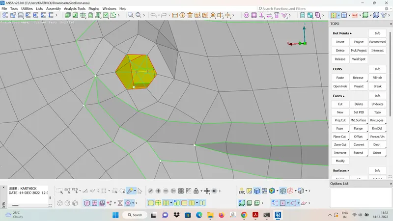
- BOLT CONNECTION
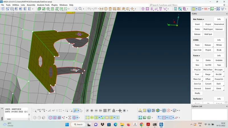
- HINGE CONNECTION
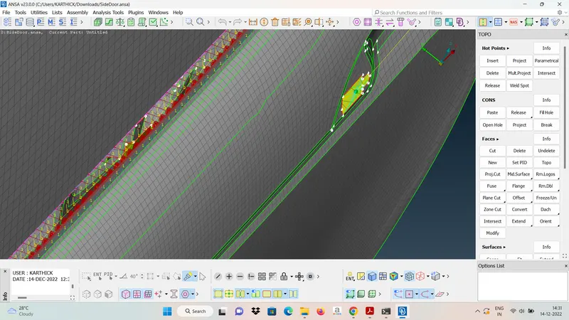
- C-BUSH CONNECTION
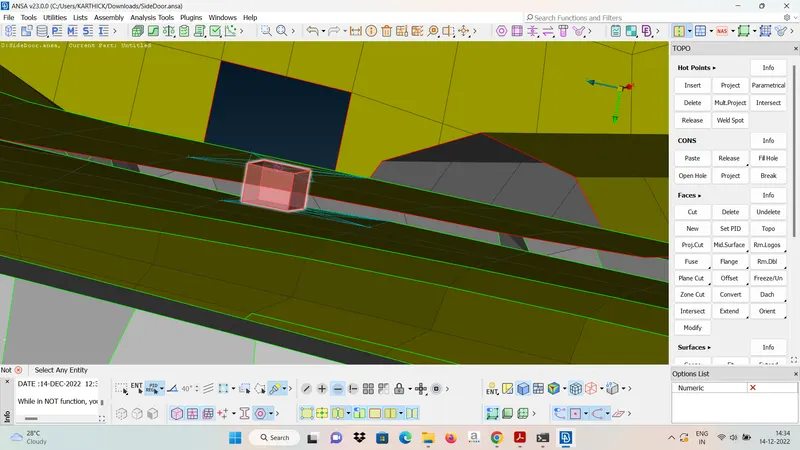
- SPOT WELD CONNECTION
CONCLUSION: Therefore the given FE model is checked for all requirement and connected using connection manager in suitable area.