Week 6 - Creating connection for Rear door
Aim:
To perform different types of 1D Connection on Rear door FE model using ANSA Preprocessor.
Procedure:
Step 1 :
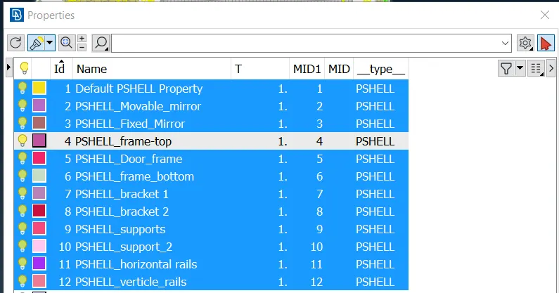
Rear door FE model has same PID for the whole component, To realize all connection need to seperate different part of the model into different PIDs.
Step 2 :
RBE2 connections.
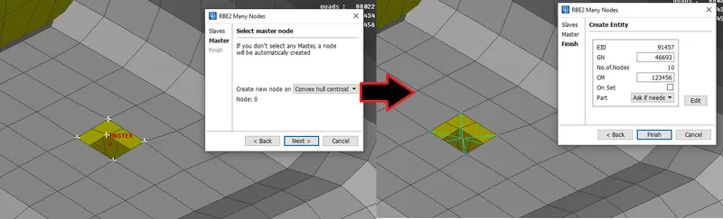
The RBE2 tool can be accessed via Elements > RBE2 in the NASTRAN deck. It primarily has the 'many nodes' and 'two nodes' options. In the following example, we deploy the 'many nodes' option to connect two holes with a single master node. This is merely done by selecting the two sets of nodes surrounding the holes and letting the algorithm create a master node and form connections by running through the straightforward process. This is also known as a cluster node RBE2.
Then there is the two-node RBE2 process. This involves connecting two sets of RBE2 spiders using a double con. The RBE2 component is created separately for each hole using the Elements > RBE2 > Many Nodes option discussed before. Through this process, we'll have two master nodes (which are to be connected). To connect them, we shall be using the Elements > RBE2 > Two Nodes tool. Then it is just a matter of selecting the two master nodes to form the connection. This is typically used in cases where assigning properties for the bolt stem might be a requirement.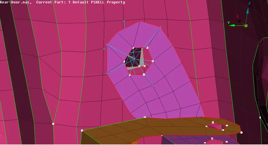
However, in this case (which is a hinge), care must be taken to assign the D.O.F.s accordingly. A hinge joint requires yaw movement and as such will have 5 D.O.F.s fixed. Meaning, when defining it during the Two Node RBE process, care must be taken to ensure the value of 'CM' is 12345 (instead of the standard 123456) to allow rotation alon z axis.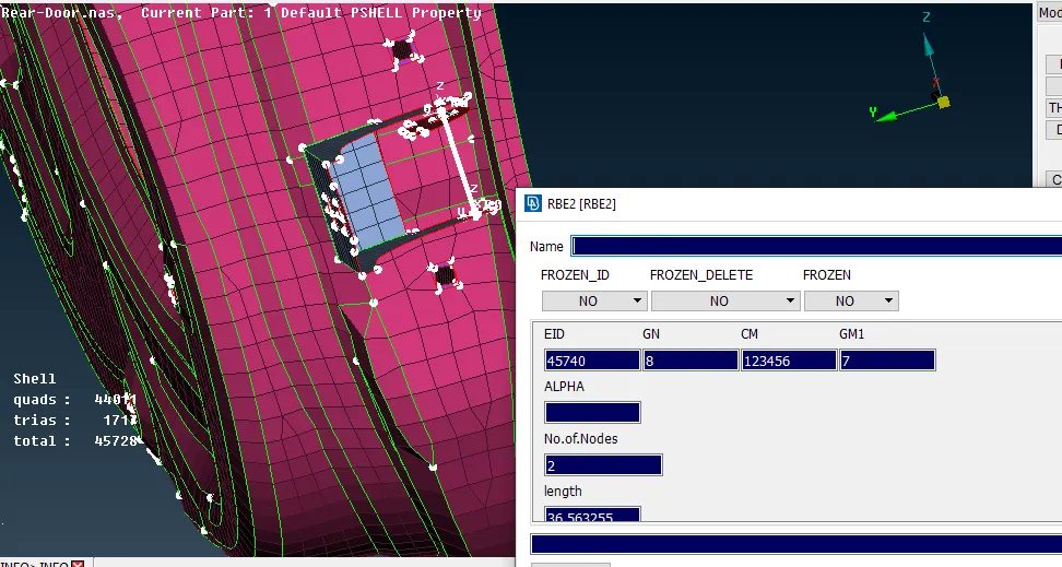
2. There is another way to assign bolt connections which becomes especially useful in cases where there are more than 2 layers that require connecting. This will involve using the connections manager. Before that, we need to create a COG point in one of the holes from a layer in the middle (using the Points > on COG tool from the topo deck).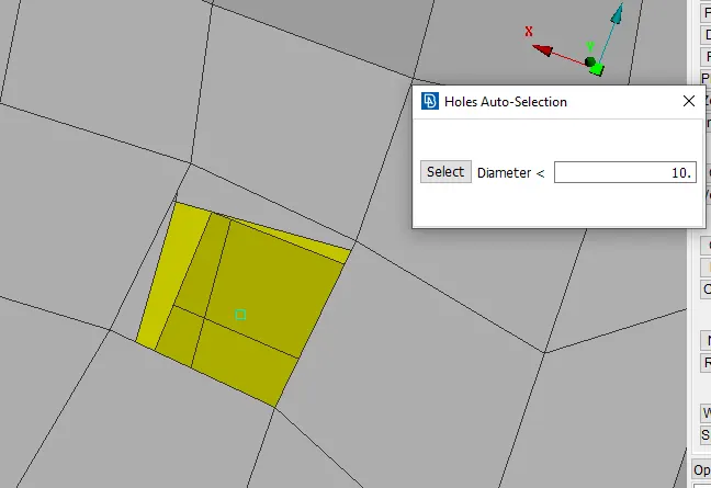
Then the point needs to be converted into a bolt using the convert tool from the upper toolbar (selecting 3D points).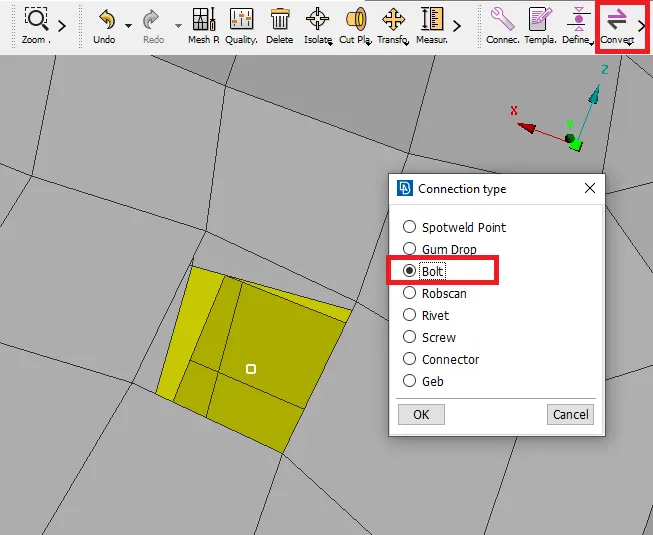
After converting the point into a bolt, the connection manager is accessed (from the top toolbar) and the bolt point selected. Clicking the middle mouse brings up a set of options that needs to be edited in order to develop the proper bolt connection.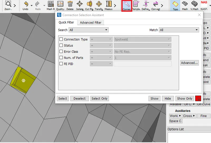
In the set of options, the sections P1, P2 & P3 need to be assigned (since there are three layers). The part on the same plane as that of the bolt point would be P1 and the others can be assigned interchangeably. To select the PIDs for each, right-click on the option (P1, P2 or P3). A box pops up. There, we need to press F1. This will let us select the particular PID.
The FE Rep Type needs to be 'BOLT'. The search distance can be assigned according to the distance from the bolt point (such that the algorithm would detect the other holes in the search distance). I assigned 30mm in this case. And finally, the Zones option would be 'inner'.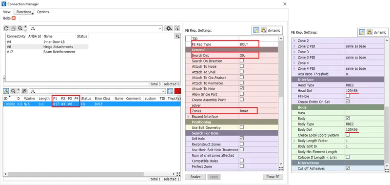
Step 3 :
Spot weld connections.
Some parts at the railing are required with spot weld, to obtain those connections they are connected with RBE2 Hexa RBE2 connections with giving the Solid PID and for P1 and P2 as they initial and secondary surface. First, they are created with a 3D point converting them and giving connections of RBE3 Hexa at the connection manager.
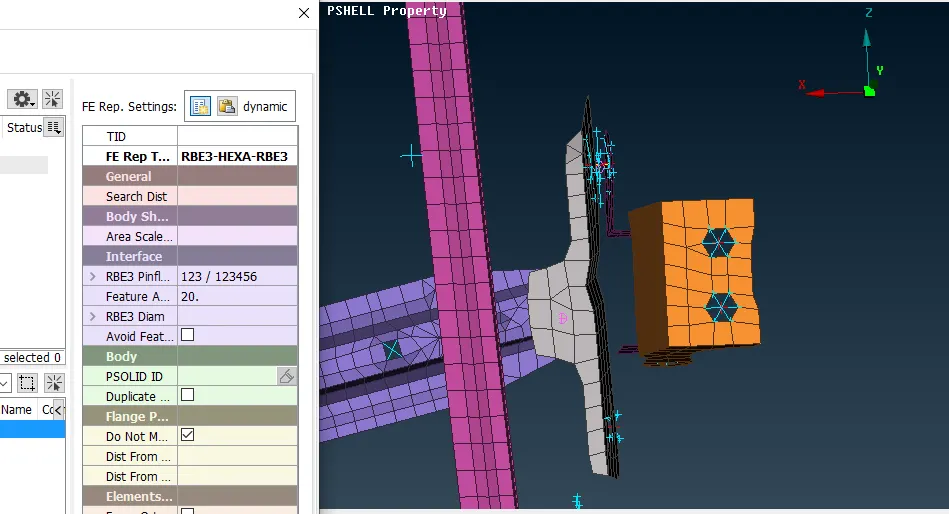
Fig 8: Connection manager spot weld
Giving the values and input in the connection manager the spot weld is deployed with on railing system
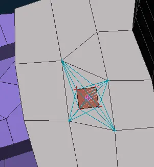
Step 4 :
Handle with CONMi connections.
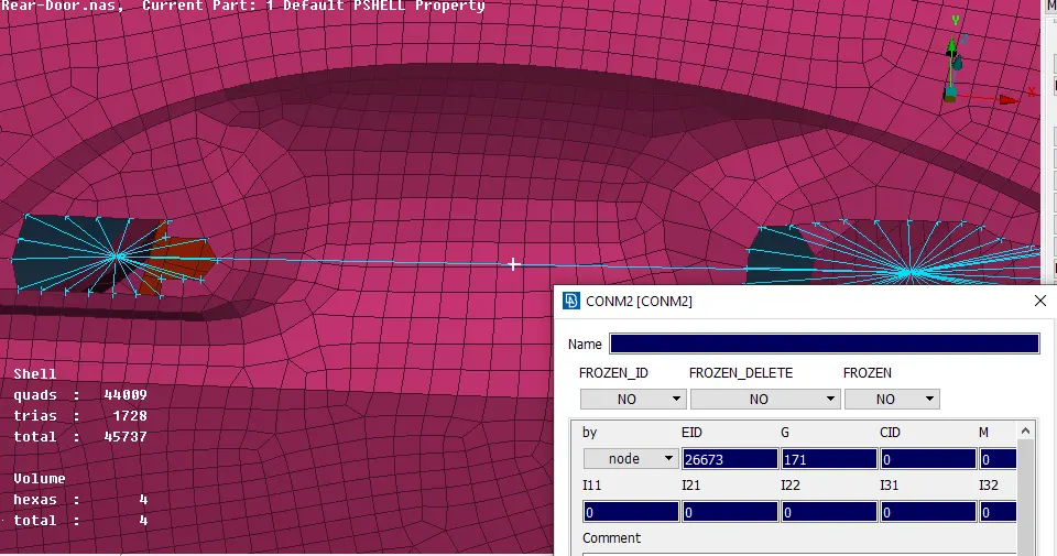
handle are connected with RBE2 rigid elements and the master node of both connections is connected with a two-node connection non them to apply conmi mass. The two-node connection will give the master node in the middle so applying mass in the middle of 10 (0.0001 tonnes) for the simulation process.
Step 5 :
CBUSH connections (weather strips).
connection involved in this challenge would be that of CBUSH RBE3 elements, which will be used wherever window weather strips (seals used to keep interior air in and external elements out) are involved.
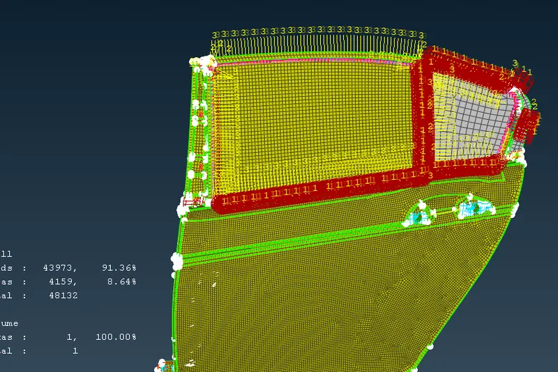
The procedure to get the CBUSH first selecting the edges of the glass and creating the feast 2curve and at the base copying the curve at a distance of 10, those curves are converted to spot weld and selecting that connection is given appropriate value in the connection manager by selecting S = 10, P1 and P2 wherever required necessary P3 is due to the three surfaces. The PID for the bush is given with stiffness value.
| K1 | K2 | K3 | K4 | K5 | K6 |
| 1 | 1 | 1 | 10 | 10 | 10 |
And the search distance of 50 and taking all branches selected applying and realizing the bush.
CONCLUSION:
I done the model & Acheived required Connections for rear door.
The rear door has an important aspect of connection in the vehicle body they are connected with several rigid elements, spot weld, and Bush elements. To deploy the proper connection they are input with exact values and the group of RBE2 elements set is created to determine them easily and this challenge is also overcome with other elements such as spots weld, handles CONMi mass, bolt, and RBE3 Hexa (CBUSH).