Week 6 - Creating connection for Rear door
AIM: To create a 1D connection in the Car Back door with the different connections that is available in the ANSA GUI.
Objective:
To perform the different types of connection that need to be done in the Car Door.
Procedure:
Import the FEA (meshed) model into ANSA GUI.
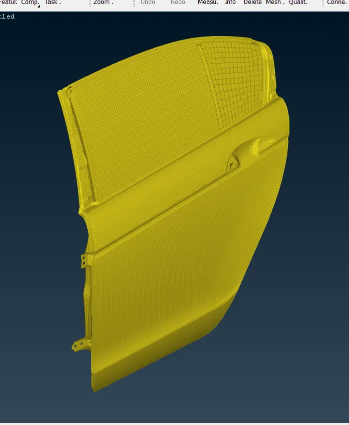
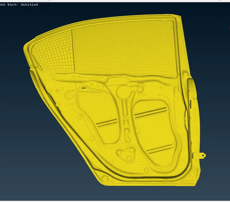
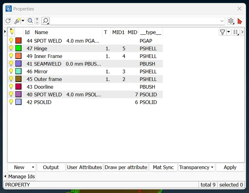
Set a Separate PID region for each panel of the component, which shown below:
Bolt Feature:
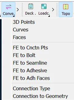
To create a Bolt element, first we have to create a COG where the bolt has to be created, by using the "Convert" option in it, after converting the points to 3D point we have convert that 3D point into bolt connection by using "Connection" option,
Select the point, click the P1 PID to assign the PID where to bolt feature as to attain, to assign PID in P1 click on P1, then press " / + Shift" option and select the property for P1, and similar steps to be followed P2, P3, P4 as well.
For this select the "BOLT"
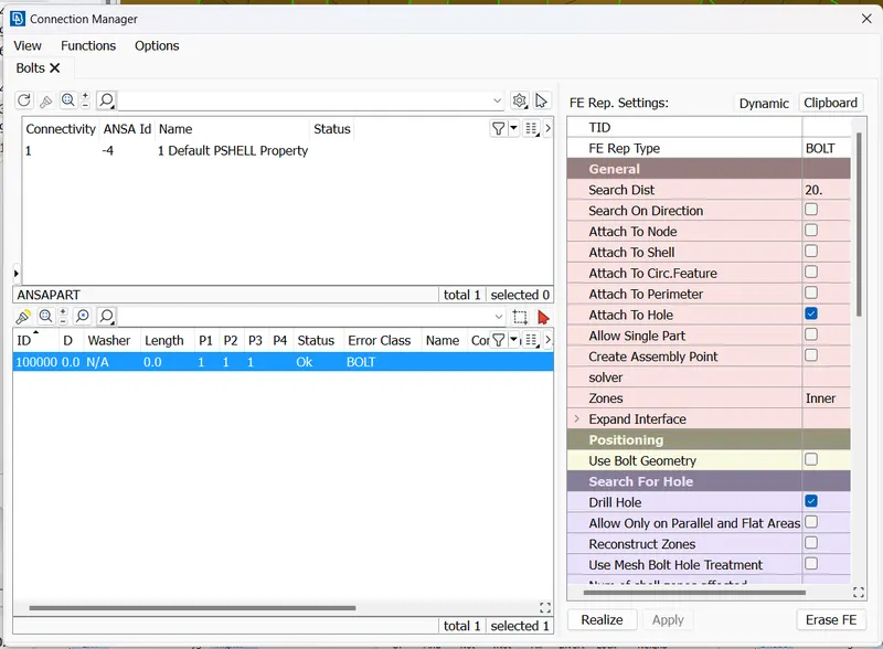
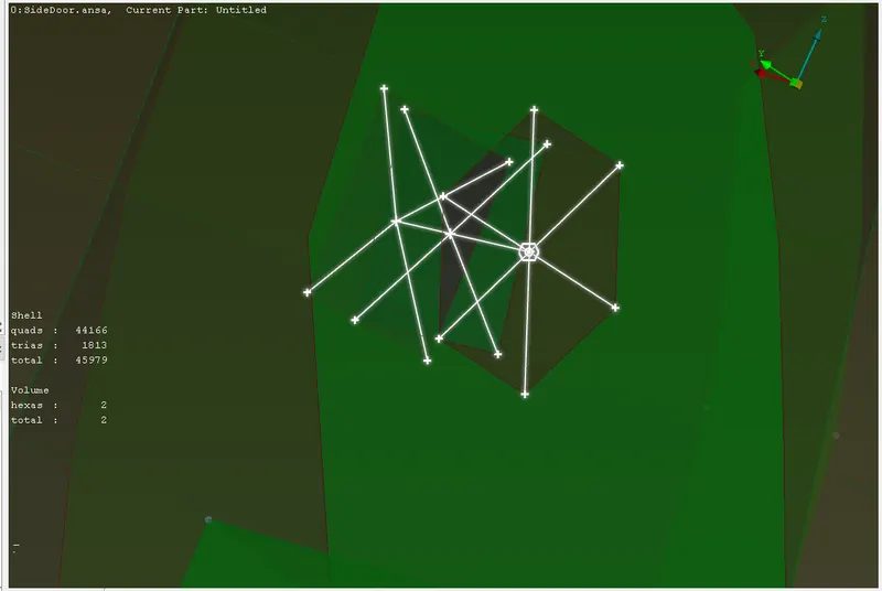
As shown in the image, connection meant be done for the Bolt operation.
SPOT weld:
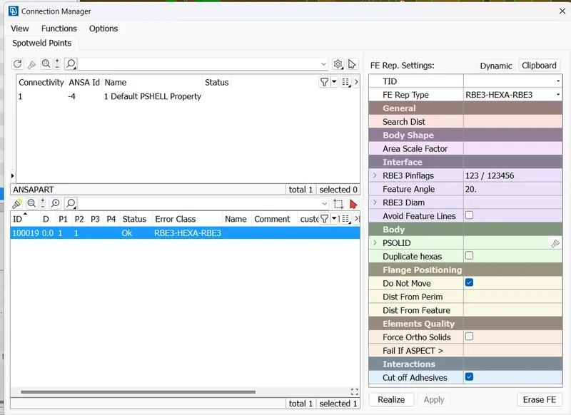
To create a seam weld, first we have to create a COG where the bolt has to be created, by using the "Convert" option in it, after converting the points to 3D point we have convert that 3D point into bolt connection by using "Connection" option.
Select the point, click the P1 PID to assign the PID where to bolt feature as to attain, to assign PID in P1 click on P1, then press " / + Shift" option and select the property for P1, and similar steps to be followed P2, P3, P4 as well.
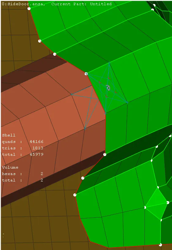
For this select the "RBE3-Hexa-RBE3"
RBE2 Feature:
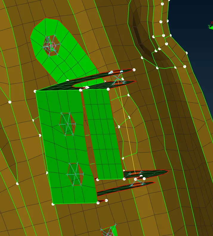
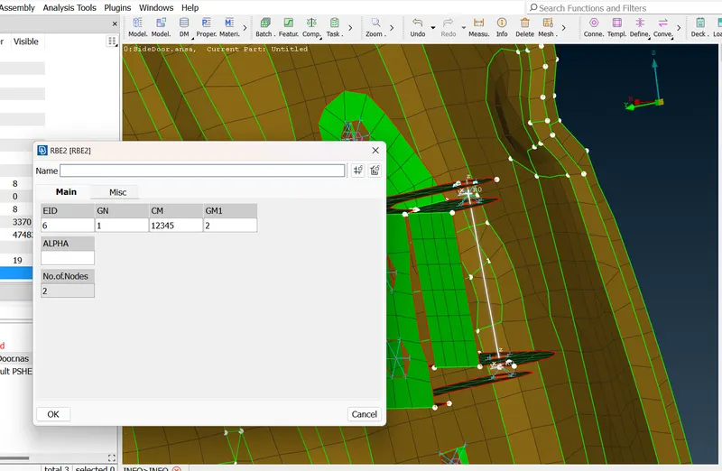
To create a RBE2 element, we have to go for NASTRAN tab, select RBE2 element , click Multi nodes, and Features angle to capture the connection which are connected closer to it.
For HINGE of the DOOR,
we have created 5 DOF only due to some constrain, act in the Global Z axis, If we give Rotational Z axis while simulated the model in the solver, it term to act the door in the vertical rotation, to control that kind of error we are arresting the Z axis by not giving the value of rotational Z axis.
For the Rest of the feature RBE2 is followed.
MASS Feature:
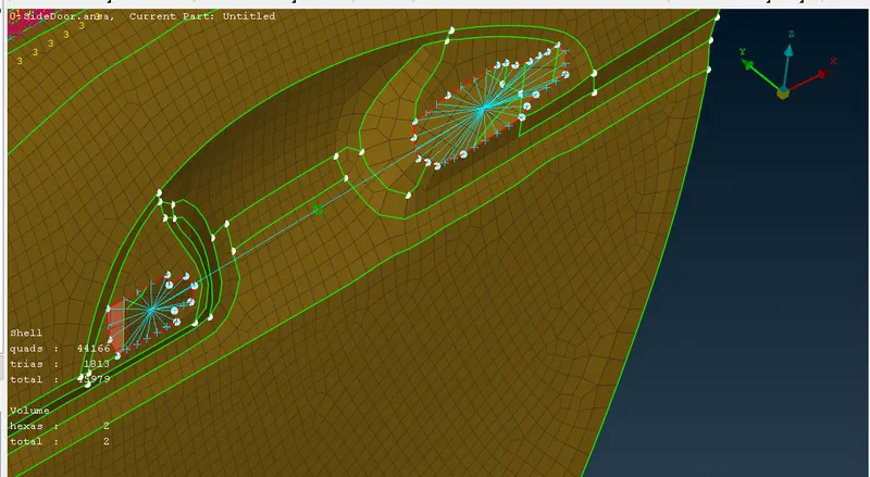
To create the CMASS in between of 2 RBE2 element, go to Tab "NASTRAN -> Elements -> CMASS", once assign the master nodes for the Handle, select the nodes to assign the mass into, always use Ton represent value in the CMASSi.
SEAM (CBUSH) weld Feature:
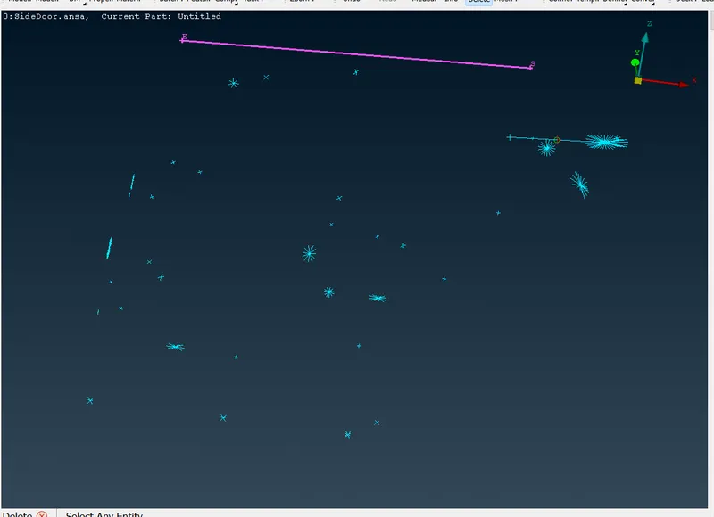
To create SEAM weld, first we have to create a feature curves of the feature where the curves has to be created, by using the "Convert" option in it, after converting the points to curve lines we have convert that Curves into bolt connection by using "Connection" option.
connections for windows aka mirror:
- create curve around the perimeter of the window.
- transform them into spot lines.
- select the lines after opening CONNECTIONS MANAGER RBE3-CBUSH-RBE3 is used to represent Window Connections because windows are connected with soft bending to absorb shocks.
Select the point, click the P1 PID to assign the PID where to bolt feature as to attain, to assign PID in P1 click on P1, then press " / + Shift" option and select the property for P1, and similar steps to be followed P2, P3, P4 as well if needed.
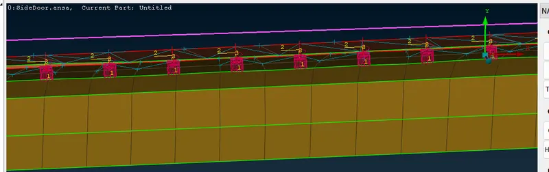
For this select the "RBE3-Cbush-RBE3"
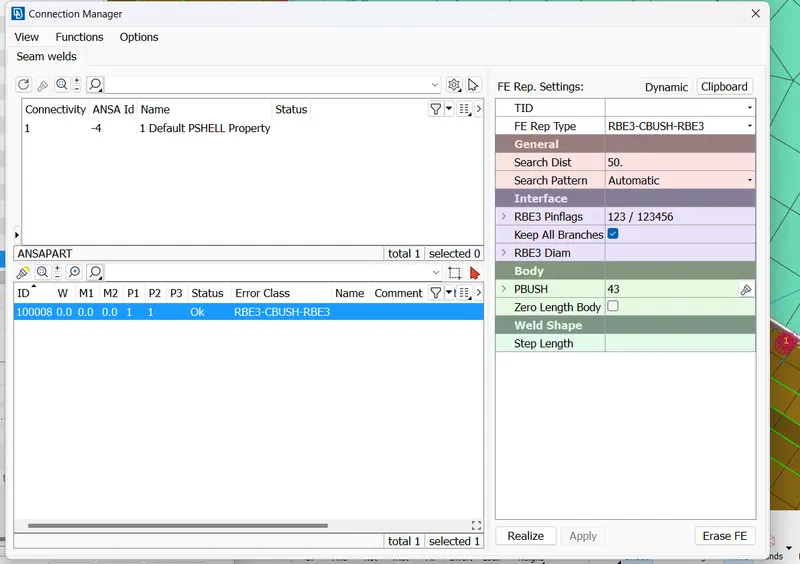
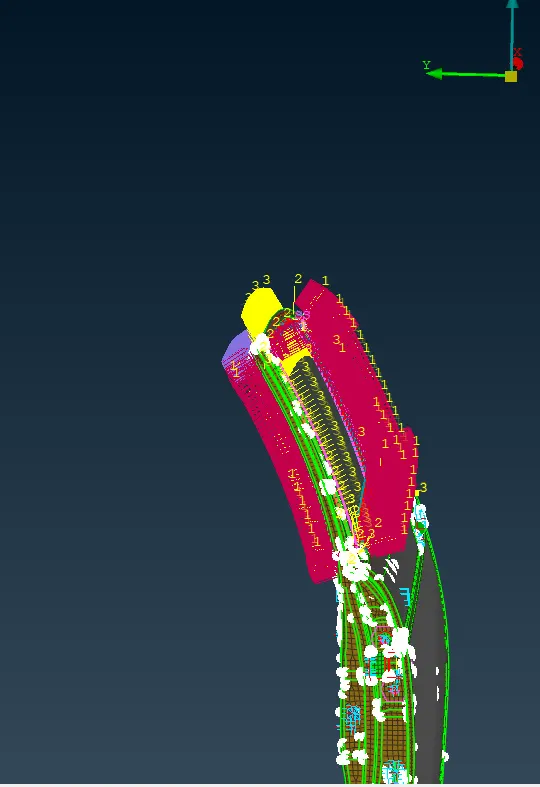
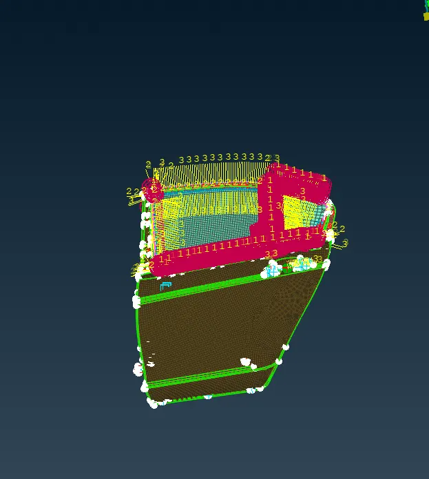
The Below image is the represent for 1D connection:
Conclusion:
- Rigid body element are connected.
- Spot welding component connections are made.
- CBUSH element are represented
- Mass of Handle is represented
- Degree of freedom assigned for hinges.