Week 6 - Creating connection for Rear door
AIM;
For the given Rear door FE model, Create and Apply different PIDs for different components. By using the same technique and the elements as shown in the video, Perform suitable connections.
PROCEDURE:
- Download the model from the challenge.
- In the given we find all component in same PID. So For simple connections and understanding of different parts we have separate the different PID for different parts.
- After completion of assigning the different parts, check which part is to be connected with which joint.
- In this particular model the most common connection types will be Bolt-nut connection, and some parts connection without nut-bolts, spot weld connection, seam weld connection, bushing connection for window glass, etc. We will be taking a look at them one by one.
TYPES OF CONNECTION:
- We need to joint two different parts by using different methods but here we used the bolt connection and rigid connection.
- If we want to connect the two subsystems using rigid connections. It can be done by manual method and automatic model.
- We use RBE2 connection when two parts doesn’t have any holes, generally here we can also use the components, we use spot weld type of connection to represent them.
- IF we have to connect two components representing a structural attachment with the model where they have to bear a lot of load, stresses as compared to simple components we use seam weld type of connection.
- For any attached entities to the model such as Door handle or Mirrors, we need not to represent the whole FE representation, we can just create many node RBE2 connection where they will be mounted, create a two node connection for connecting different mounting positions and define a mass on the COG of the entity.
- For representing the connection between window and the door body, we will be using CBUSH type of connection. For this we have to create curves along the body of window, convert them to the spot line connection and then going to connection manager and select P1,P2,P3 accordingly, specify the space between the bushes, create a new PID for bushes and deploy the connection.
Manual connection:
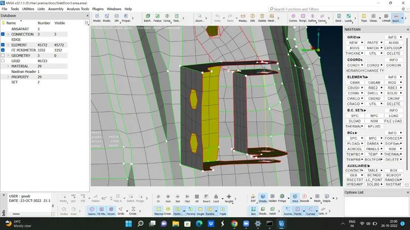
In manual connection. We are using bolt connection between the three plates. We need to go for NASTRAN MODULE> ELEMENTS > RBE2> MANY NODE> SELCT THE NODES OF HOLE > NEXT> (it automatically takes master node) > NEXT > FINISH.
Automatic connection (BOLT CONNECTION)
In automatic connection is simple it is used when a greater number of connections are required to make. For this we have make 3D point between two mating plates. Convert the 3D point into type of joint. Now we have define joint in connection manager. Double click on the bolt joint. We have to assign the parts which we need to connect. Give the space dist according to the distance between the parts. Create the PID for joint, click Apply and Realize. The bolt connection will be established, 2 rigids will be formed in case of 2 part connection and the middle line will represent the stem of the bolt.
SPOT WELD CONNECTION (RBE3-HEXA-RBE3)
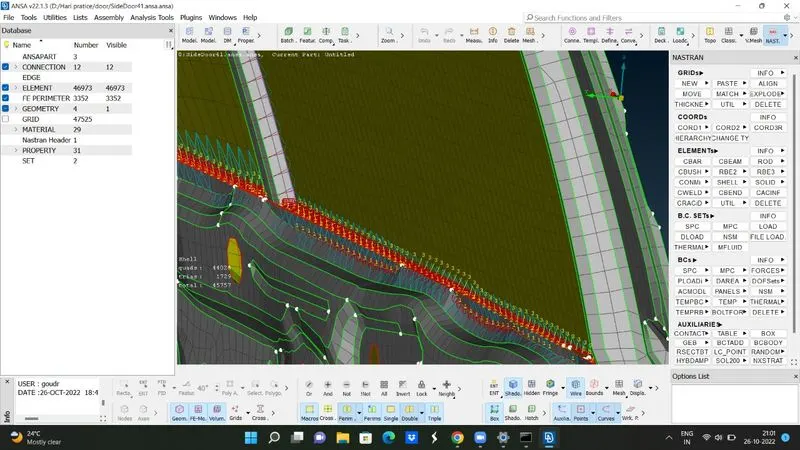
Crete a 3d point between the two-mating surface. Convert that 3D point into spot weld joint. Go for connection in connection manger. Assign the parts to joint. Give search distance. Assign the proper DOF. Click on apply and realize.
DOOR HANDLE CONNECTION
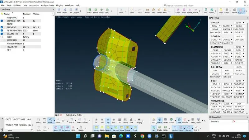
It has special type of connection. In this model we have two holes for handle can sit. Here we have to create a RBE2 connection at two holes. After this we have select RBE2 option. And select master point last two rigid connections. It will also give the master node. At this master node we have to assign the mass of door, by selecting CONMI and give mass (note: we have provide mass in the units of tons)
CBUSH CONNECTION(RBE3-CBUSH-RBE3)
Create curves along the area where we want to deploy the connections. Convert them curves to spot line by selecting them one by one. Select the connection type as spot line in Connection selection assistant. In the connection manager apply proper spacing for the bushes, select the parts between which we want the bush connection, give proper FE rep type, assign search distance, create and apply new property for the cbush, click apply and realize. Repeat this for all the four sides of the window.
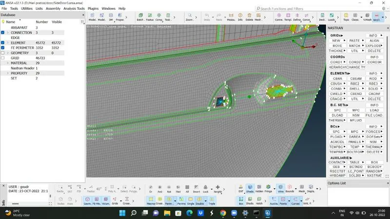
NOTE: we have check that direction or orientation of the cbush formed. We have to assign the vector direction such that it should follow the global co-ordination system. These will help us to avoid the confusion.
LEARNING OUTCOMES:
- Basic of connection
- Different types of connection
- How to make the connection
- Deploying the connection in manual and automatic method.
Conclusion:
In this assessment I came to know deploying of the connection. In the beginning of the connection this assessment I felt it will hard but making and practicing of different connections it become very easy.