Week 6 - Creating connection for Rear door
Aim:
The aim is for the given Rear door FE model, Create and Apply different PIDs for different componentsa and to perform suitable connections.
Procedure:
Type Of Connection in ANSA-
- Rigid- RBE2 AND RBE3.
- Seam Weld-Y-Joint weld And Overlap Weld.
- C-Bush Element.
- Spot Weld Creation.
- Bolt.
CAD MODEL-
The given model is opened in the ansa by open command,
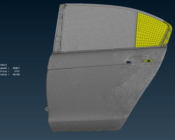
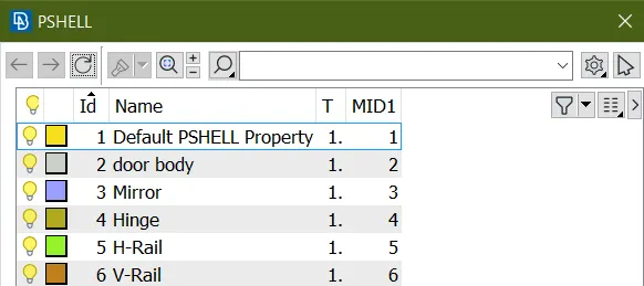
After importing the model and create new PID as below image.
2) Deploying a connection at the door handle:
Then the connection is deployed at the door handle region.
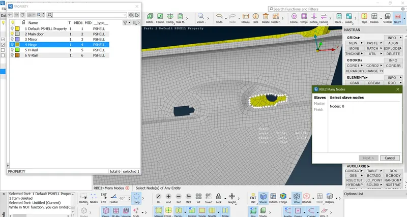
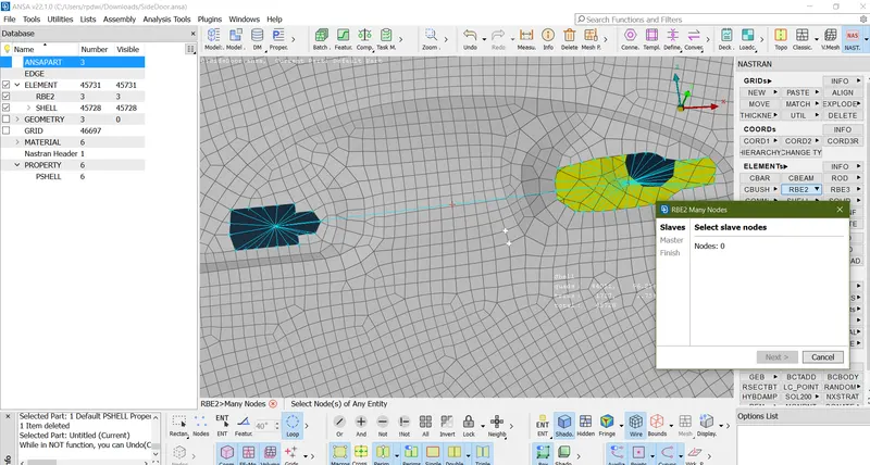
Initially, the RBE2 elements with many nodes option is used to connect all nodes at the perimeter of the handle.(Nastran>Elements>RBE2>Many Node>select door node With LOOP selection tool)
Steep-1
Select node as shown below image
Step-2
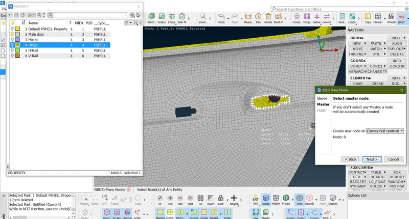
Once node selected hit the middle mouse click and master node shown in center of selected area.
Step-3
Connection deployed
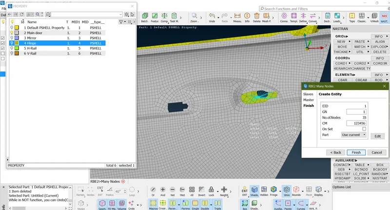
Step-4
Do same operation in second area
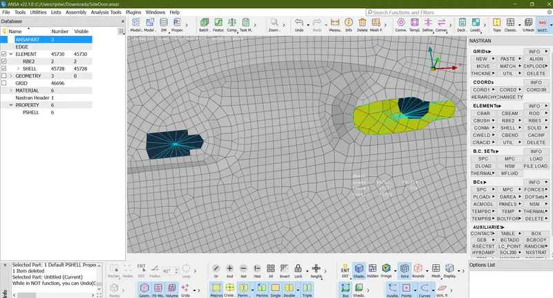
Step-5
Select 2 node with help of (Nastran>Elements>RBE2>Two node>Select 2 node)
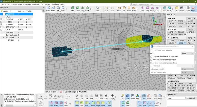
Step-7
Turn into master node In center.
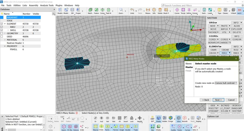
Step-8
Step-9
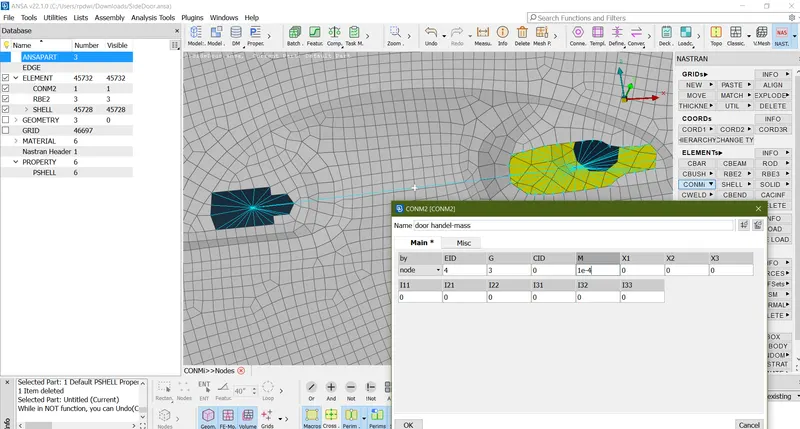
Then to represent the weight of the door handle, as in case of real world scenario. The mass can be assigned by using the (Nastern>Elements>CONMi> CONM2> Nodes). In NASTRAN deck module
A weight is assumed as 1 kg and entered as "1e-4"(Which will be in the form tonns)And this is applied to the master node at the center
Step-10
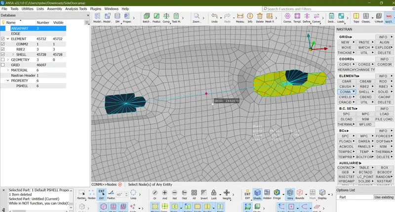
After assigning the mass at the center master node, it will be represented as highlighted
3) Deploying a Connection between the rail & side glass-
Create spot weld following stages-
1)Create 3D point(Tool>Point>ON COG>Select face)
2)Covert the 3D point(Assembly>Convert>3D point>Click COg Point>Middle click>3D ponit convert into bolt)
3)we have to use the connection manager and we have to select connection(Assembly>Connection Manager >Select the bolt entety>middle click.Coonnection manager window open)
4) Select the PID'S(P1,P2,P3...)
5)Provide Serch distance.
6)Create Weld point.
7)Apply And Relized.
In this step, the rail which is responsible for the movement of side glass to up & down and the side glass are only isolated to have a clarity on them.
(Classic mash>Grids>MV Free)
But the enlarged elements will be too high interms of length. So, those elements are selected and reconsturtion of elements is performed. By assigning the target element length, as by measuring any one element dimensions.
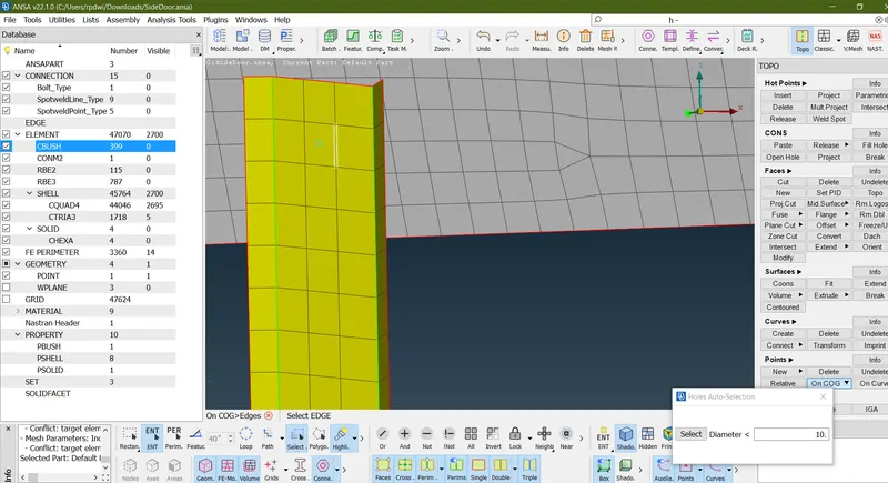
After that Attached two part Turn into spot weld. As shown in below image.
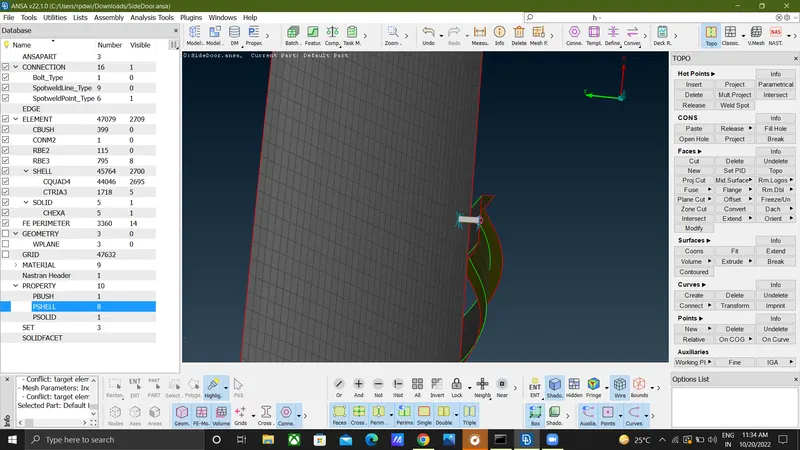
4) Deploying the connections at the side glass region:
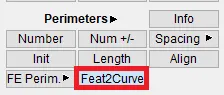
As the side glass is surrounded by a component called "Weather strip" which is made up of rubber Material And widely known as "Beading". So to represent that, the CBUSH elements are used. Because, it possess the elasticity in all three directions. So, initially the curves are needed. For that, the "FEA to curve" option in the perimeters from topo module is used.
And the FEA edges are selected one by one and then it is converted in to curves, which are represented by purple coloured lines at the edges. As shown below image.
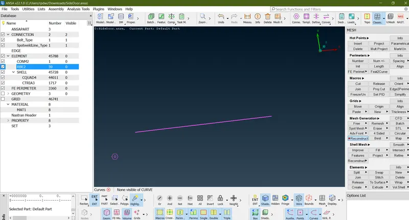
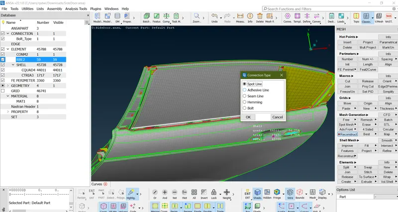
Create All Curve.
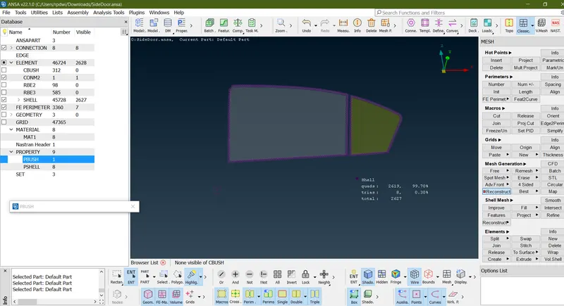
As the weather strips will be at the both sides of the glass at the bottom, the CBUSH elements should be deployed at the both sides of bottom. For doing that, the curve created at the bottom should be copied by using "Transform" and moved to a certain distance such as 10mm.(Transform>Copy>Select the curve>Give Value[10]>Middle click>Finish)
Then these curves are converted in to "spot line". And then this spot line is realized by selecting the line by line and specifying the parameters such as spacing between the CBUSH elements as 50 mm, specifying PART1 & PART 2, specifying FE represntstion type as "RBE3-CBUSH-RBE3" and assigning RBE3 pinflags(DOF-123456) in all directions.
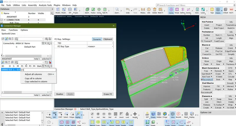
hen the PID should be created, which is done by selecting "Shift+?" from key-board by placing the cursor in the PBUSH ID row As above image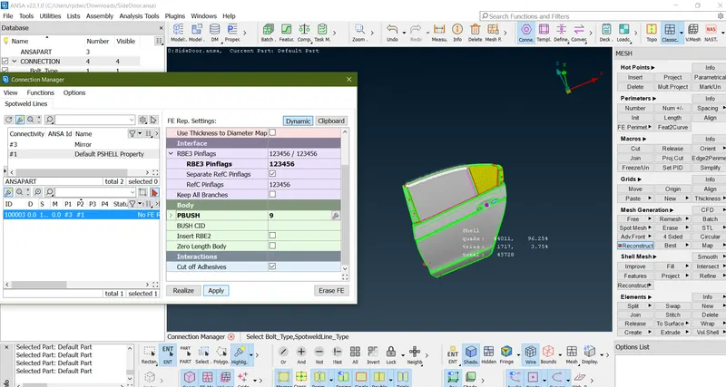
After selecting a "new" option, a diaog box appears.Which represents to PID for the CBUSH elements. In that, the 6 stiffness values are entered, which are predfined.
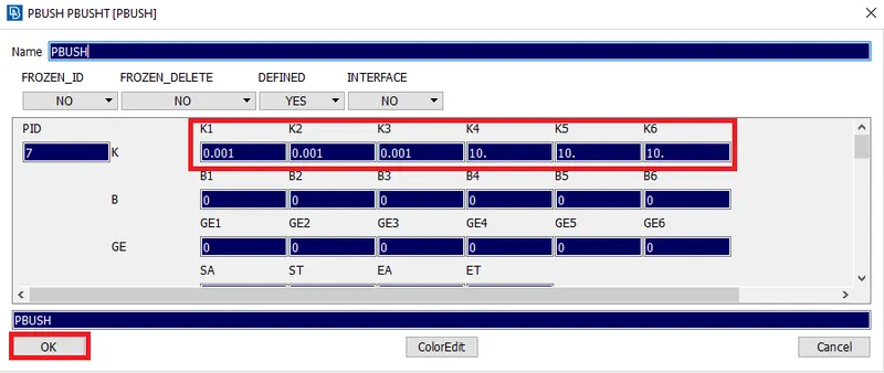
After creating the new PID for CBUSH elements, the CBUSH elements will be formed in between the side glass and outer part.
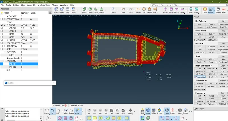
Initially, any one of the element is selected and the orientaion is choosed to "With Cord", which means "With respect to co-ordinate axis. And the CID is given as "0".which depicts that, the orientaion with respect to global co-ordinates.
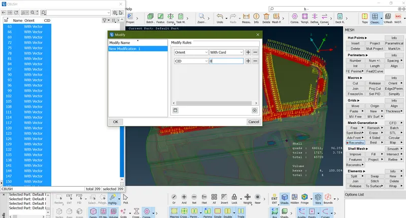
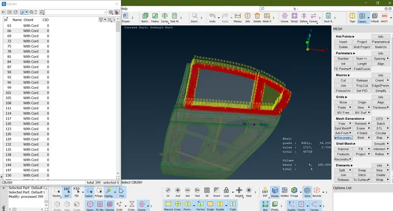
After clicking "Ok", all CBUSH elements will be in same orientation.
Learning outcomes:
By performing this challenge, the following aspect can be learned:
- Deploying connections using rigid (RBE2) elements in ANSA.
- Deploying connections using ON COG Of Bolt joints in ANSA.
- Deploying connections using CBUSH elements in ANSA.
- Applying the mass to a node(At the door handle).
- Assigning the Degrees of freedom for the created elements.
- Changing the orientations of CBUSH elements.
- If The reconstruction of mesh element by using split comand.
-
Result -
- Hence the Connectors have been deployed successfully to the car rear door component by using RBE2,RBE3-CBUSH-RBE3,RBE3-HEXA-RBE3 and CONMI2 element.