Week 6 - Creating connection for Rear door
This week, the connections for the front door by using different 1D elements are taught in detail.
Now for the given Rear door FE model, Create and Apply different PIDs for different components. By using the same technique and the elements as shown in the video, Perform suitable connections. (No thickness need to be assigned to FE as intention is just to deploy connections)
(Refer “Model Requirements” in “Grading Policy” to know what to be done in the model)
- OBJECTIVE:
To set PID and perform connections for the given rear door model with different connection techniques using ANSA.
- Aim- To provide proper connections and learn appropriate use of the connections
PROCEDURE:
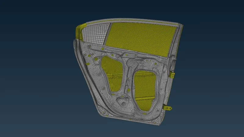
- The given model is imported into the ANSA software. It is observed that a default PID is set for the model. The imported model is shown in the figure below.
- Now go to Mesh>>Macros>>Set PID and select the desired part using the boolean operations and create the New>>PSHELL property for the selected component. The set PIDs are shown below.
- Bolt connections
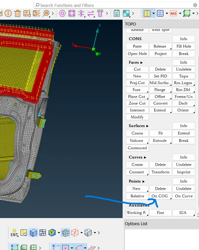
Go to Topo>>Points>>On the COG option. Select the edge and create a point. This is shown in the figure below.
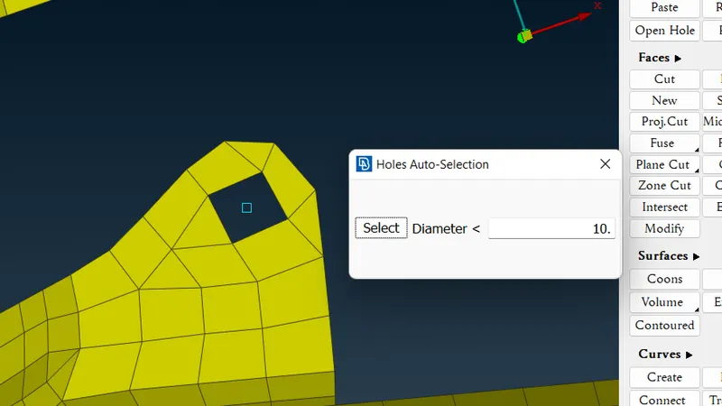
Go to the Convert option and select the type Bolt. After doing the convert option, the point is changed in accordance with the selection. It is shown in the figure below.
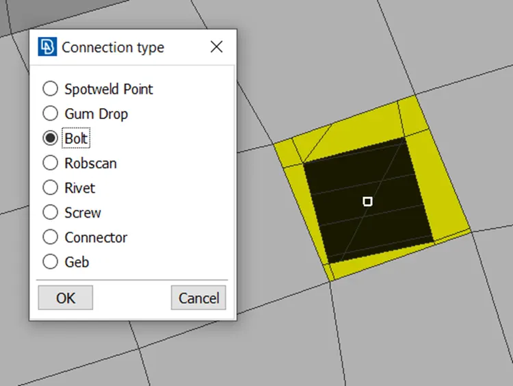
Now go to the connection option and select the bolt and hit the middle mouse button. The connection manager window would pop up.
- In the connection manager window, select the parts which are to be connected using the F1 option. Select FE Rep Type as BOLT and enter the properties as shown in the figure below.
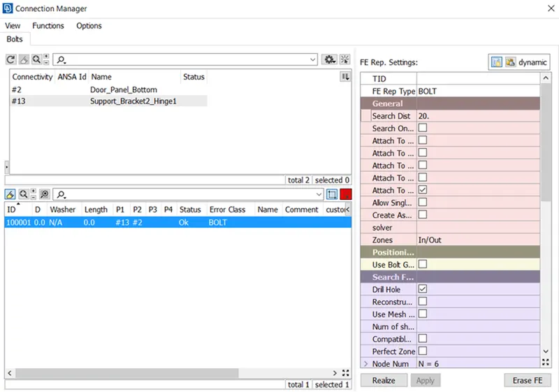
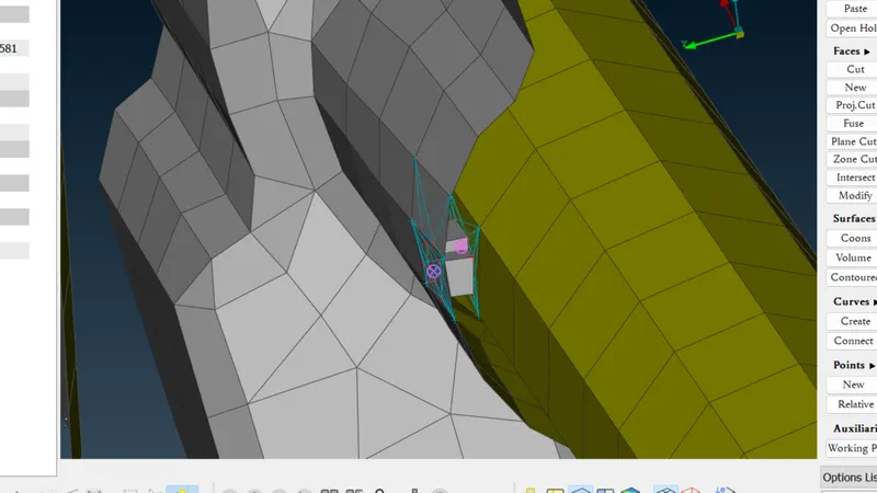
. Now click on apply and realize. The realized bolt connections are shown in the figures below.
For RBE2 Connection:
- Go to NASTRAN Deck>>Elements>>RBE2>>Many Points>>Select the points to which RBE2 must be created. This is shown in the figure below. Here RBE2 is used for realizing hinge connection.
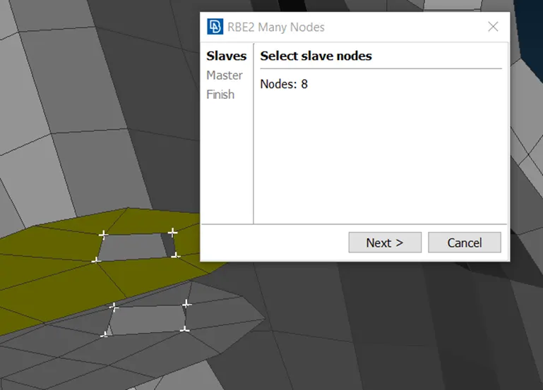
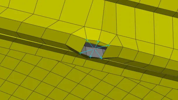
Now go to Elements>>RBE2>>Two points>>Select the points as shown in the figure below to realize the hinge connection.
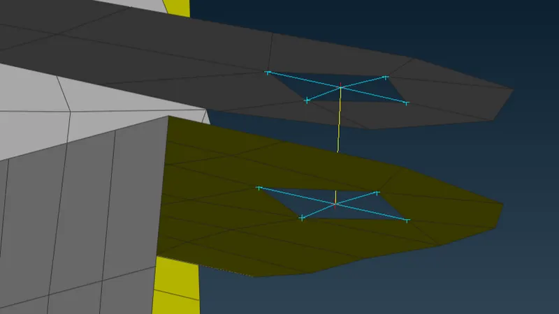
Go to Elements>>INFO>>Info>>Select the reb2 connection and give the necessary DOF's. This is shown in the figure below.
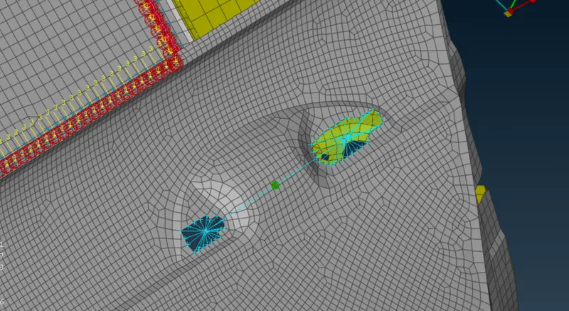
For the door handle, the rbe2 connection is established and point mass is added using the CONMi option present in the elements deck. Select CONM2 and pick the necessary node to add the masses. It is to be noted that mass has to be entered in tonnes. The realized connection is shown in the figure below.
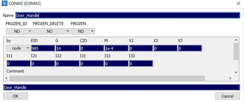
- Provision of mass to door handle
For CBUSH Connection:
- Go to Mesh>>Perimeters>>Feat2Curve option and select the edges to create a curve. This is shown in the figure below.
Now go to Convert>>Curves option and select the curve and convert it to Spotline. This is shown in the figure below.
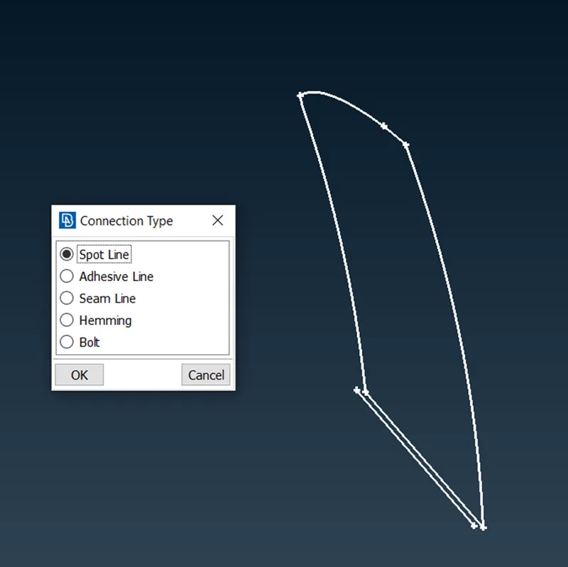
Go to connection>>select the spotline>>Middle mouse>>Connection Manager.
- Select the parts to be connected using the F1 option. Set FE Rep Type as RBE3-CBUSH-RBE3 and enter the properties shown in the figure below.
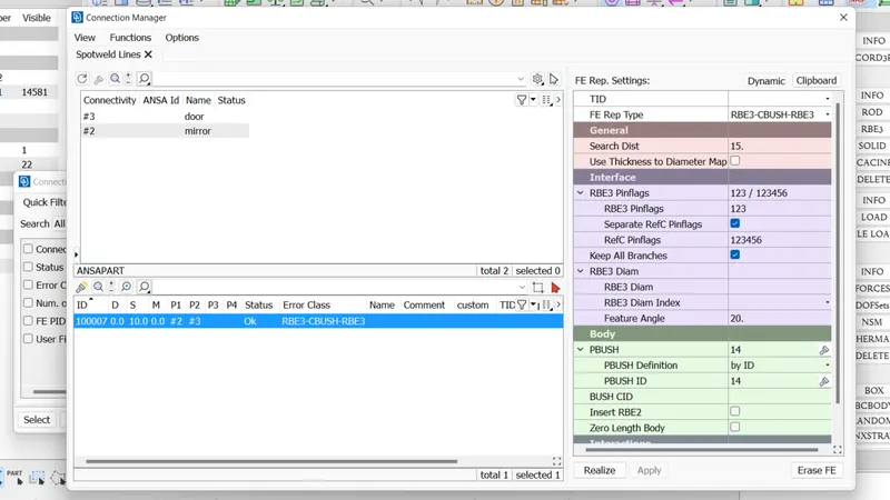
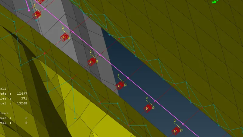
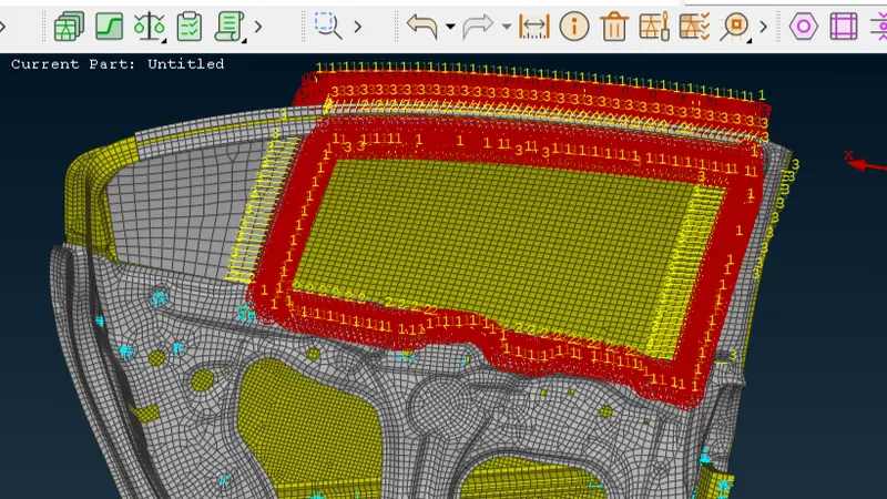
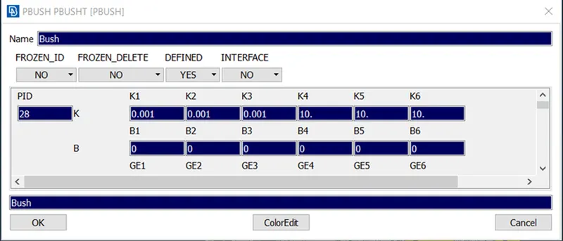
Now click on apply and then realize the connection. Now go to the CBUSH property card and select all the connections and hit on modify.
- The modification parameters are shown in the figure below. (Orient - With Coord, CID as 0). This is done to orient the CBUSH connections to the global axis.
For Spotweld Connection:
8. Go to Topo>>Points>>On the COG option. Select the edge and create a point. This is shown in the figure below
. Go to the Convert option and select the type Spotweld Point. After doing the convert option, the point is changed in accordance with the selection. It is shown in the figure below.
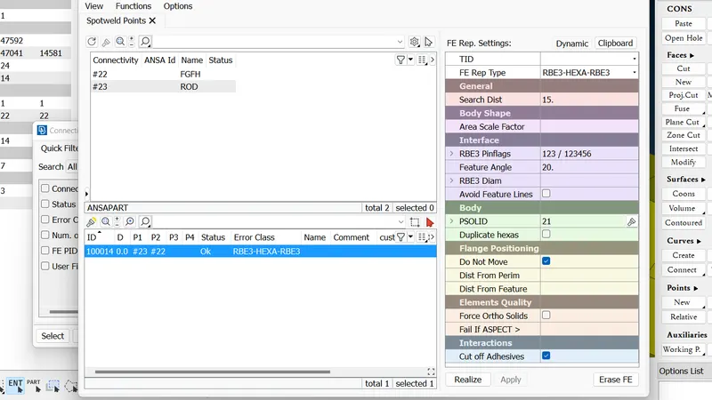
In the connection manager window, select the parts which are to be connected using the F1 option. Select FE Rep Type as RBE3-HEXA-RBE3 and enter the properties as shown in the figure below. (Here the position of the weld is taken for illustration purpose and in actuality, the position might vary)
LEARNING OUTCOME:
- In this challenge, various connections like BOLT, Spotweld, and CBUSH are learned.
- Learnt to assign PID for various parts present in the model.
- Assigning of mass for the door handle is learned.
CONCLUSION:
The PIDs are assigned to the various parts in the given model. Various connections like BOLT, Spotweld, and CBUSH are created and realized. All the given objectives are satisfied.
- Rigid body element are connected.
- Spot welding component connections are made.
- CBUSH element are represented
- Mass of Handle is represented
- Degree of freedom assigned for hinges.