Week 6 - Creating connection for Rear door
Aim
For the Rear door create and Apply different PIDs for different components and perform suitable connections.
Procedure
1. Import the FE model by using the Import option in the File menu.
2. IN the given model all components have been assigned a single PID, Assign different PID to each component by using Set PID option under the Face menu(TOPO).
3. Creating Bolt Connection wherever bolts are to be deployed.
- Bolt connection can be created by creating Multinode RBE2 elements first and then joining them by Twonode RBE2 elements.
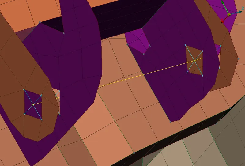
- Or a bolt connection can be created by Creating a 3D point at the Centre of the hole, then Converting it into a bolt using the convert option and finally Using the connection manager to apply the BOLT FE Rep type between the respective PIDs.
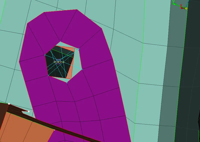
4. Creating Seam Weld
- Create a curve where you percieve to start the seam weld.
- Convert the curve to Seam curve using the Convert option.
- Open Connection Manager and select P1 and P2.
- Set FE Rep Type as OVERLAP-SHELL (for Parallel parts) or Y JOINT SHELL(for perpendicular parts).
- Set appropriate search distance and root shells and realize the connection.
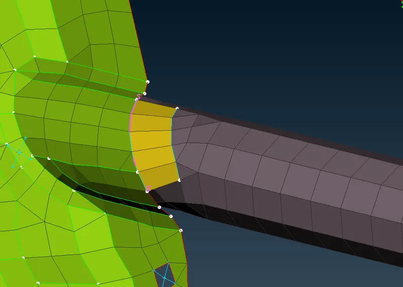
5. Create spot weld
- Create a 3d point at the centre of the element.
- Convert the point into a Spot Point using the Convert option.
- Open the connection manager (select the Spot Point) and assign the required P1 and P2.
- Select FE Rep Type as RBE-HEXA-RBE3, insert appropriate search distance and realize the connection.
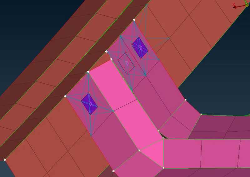
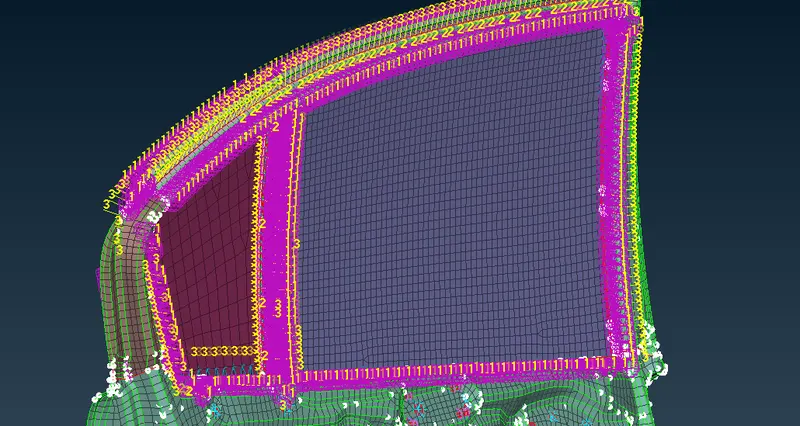
6. Create Cbush Element around the Window Panes.
- Create Curves on the periphery of the window panes and then copy the curves and offset them to an approprite distance such that connections can be created on both sides of the window.
- Convert the curves into Spot Lines using the convert option.
- Open Connection Manager, select P1 and P2 and enter the value for spacing.
- Select FE Rep Type as RBE-CBUSH-RBE3, insert appropriate search distance, Assign PBUSH ID and realize the connection.
7. Creating door handle connection.
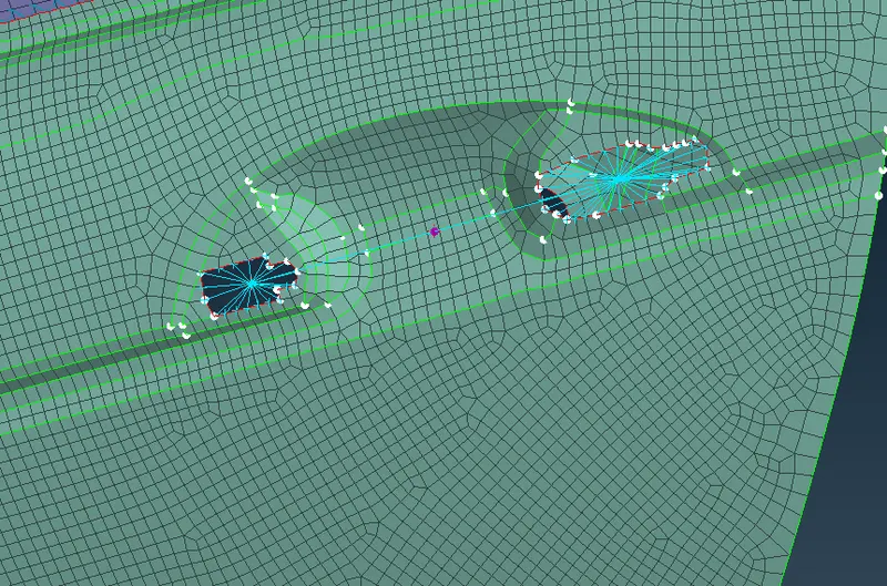
- Create Multi Node RBE2 coonections on each door handle hole.
- Select the two master nodes and create a Multi Node RBE3 with master node and the midpoint.
- Assign Mass to the master node at the midpoint by using CONM2(an option of CONMi) in the Element option in NASTRAN deck(enter the value of mass in Tonnes).
Result
Bolts, Seam welds, spot welds and Cbush connection are created and realized successfully in the given FE model.
Learning Outcome
Correct use and application of different type of connection in an FE model to connect the model appropriately for further mechanical Analyses