Week 6 - Creating connection for Rear door
Creating Connections – Rear Side Door
AIM:
To create connections for the given rear side door model.
PROCEDURE:
The following diagram provides the flow chart of the work being progressed for connecting the rear side door assembly model.
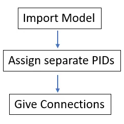
Fig.1 Flow Chart
Geometry Import: First the Rear Side Door model has been imported to the Ansa software. Figure 2 provides the meshed model imported into ANSA.
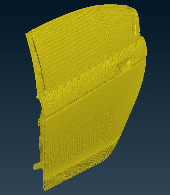
Fig. 2 The Rear Side Mirror model imported into ANSA Software
Assigning PIDs: After the model has been imported into the software, it was found that it has only one PID. So each part/component was separated and assigned to separate PIDs as shown in figure 3. Figure 4 shows the different PIDs assigned to the model.
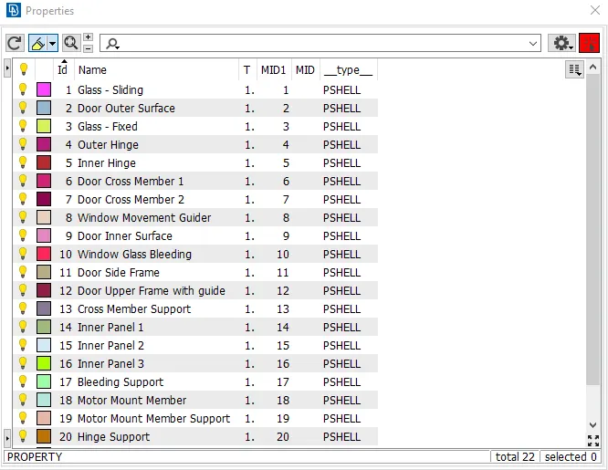
Fig. 3 Separate PIDs created for the parts in the model.
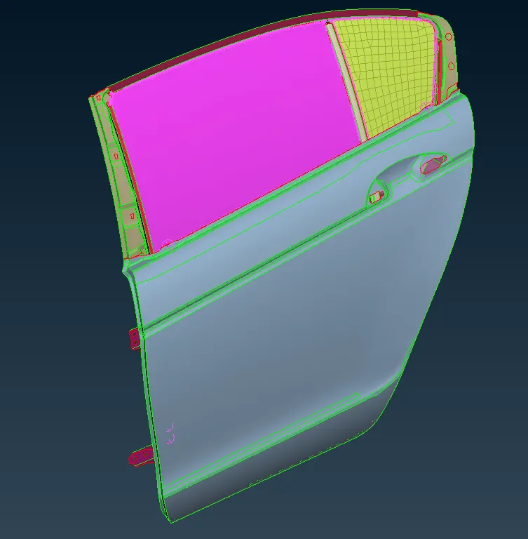
Fig. 4 PIDs Assigned in the model.
Creating Connections:
Door Hinges – For the door hinges, RBE2 using Bolt type FE Representation was used, because usually hinges are bolted to the B-pillar and doors. For that, first, the 3D point on the COG of the hole was created. Then the 3D point was converted to Bolt using Convert Tab. Using Connection Manager, the bolt represented using RBE2 was created by assigning the PIDs which are to be connected with the bolt. Figure 5 shows the Bolt type of RBE2 connections formed between the holes connecting all the surfaces.
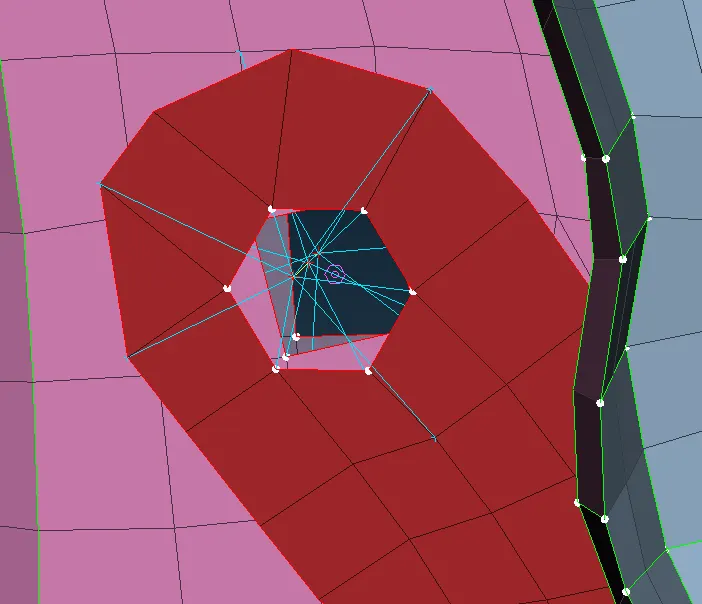
Fig. 5 Bolt Connection at Door Hinges.
Then the rotation of the door hinge mechanism was given by two node RBE2 elements having 5 DOF allowing the door to rotate in the z-axis direction. Figure 6 shows two node RBE2 elements having 5 DOF.
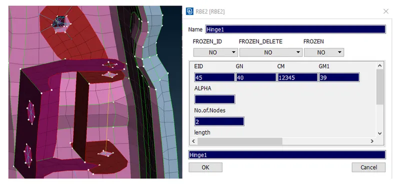
Fig. 6 Two Node RBE2 elements.
Glass Windows – The glass windows were connected using CBUSH elements. For providing damping for any part, there are only a few ways to provide that by either using CELASTIC elements or CBUSH elements. CELASTIC elements are mono-directional elements and for connecting them in three directions, we need to use three CELASTIC elements. The other easy way to represent connection is by using CBUSH elements. For the connections, first, the glass line was obtained from the FE model using the Feature2Curve option from the Mesh tab under the Perimeters section. Then the curve was converted to a Spot weld line using the Convert option. Then spot lines and surfaces were selected and assigned to PID and later RBE3-CBUSH-RBE3 type FE Representation was given and a new Bush PID was assigned to it. Figure 7 shows the CBUSH elements and figure 8 shows glass connected to the door panels using the CBUSH elements.
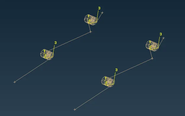
Fig. 7 CBUSH element Connection.
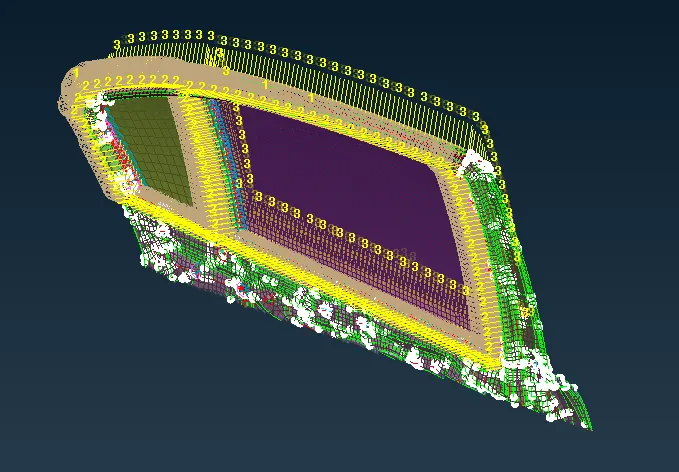
Fig. 8 Glass with CBUSH element Connection.
Finally, the CBUSH elements were oriented according to the Global Coordinates of the model.
Window Slider Mechanism – The window sliding mechanism and support member were connected using Spot welds. FOR SPOT WELD TYPE connections, RBE3-HEXA-RBE3 type FE Representation was used and the surfaces to be spot welded were assigned and the connection was given. For that first, a COG 3D point was created and then converted to a Spot weld point followed by providing the surface and FE Rep type. Figure 9 shows the Spot Weld Element formed and figure 10 shows spot welded elements.
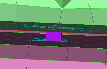
Fig. 9 Spot Weld Element.
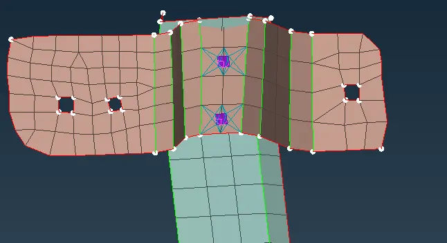
Fig. 10 Spot Welded Surfaces.
Spot Weld Connections: The following figures show the surfaces and areas that are spot welded together.
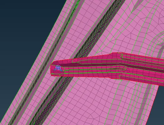
Fig. 11 Door Inner Panel – Cross Member – Spot weld.
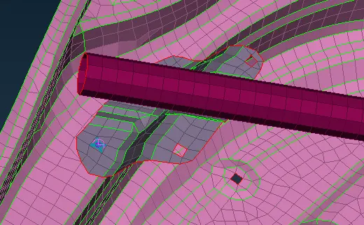
Fig. 12 Door Inner Panel – Cross Member Support – Spot weld.
The Door Inner Panel and Cross Member and Cross Member Support were spot welded together because they can’t be bolted together and as well as they don’t have hole provision for bolting together.
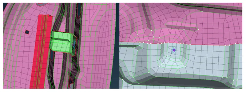
Fig. 13 Spot Welded Surfaces.
The Spot Weld Elements were used where there are no holes or provisions for bolting the surfaces together.
RBE2 Connections: The RBE2 elements were used where there are holes or provisions provided so that the surfaces can be bolted or joined together rigidly. RBE2 is used for providing rigid connection to the surfaces, such that it arrests all 6 DOF.
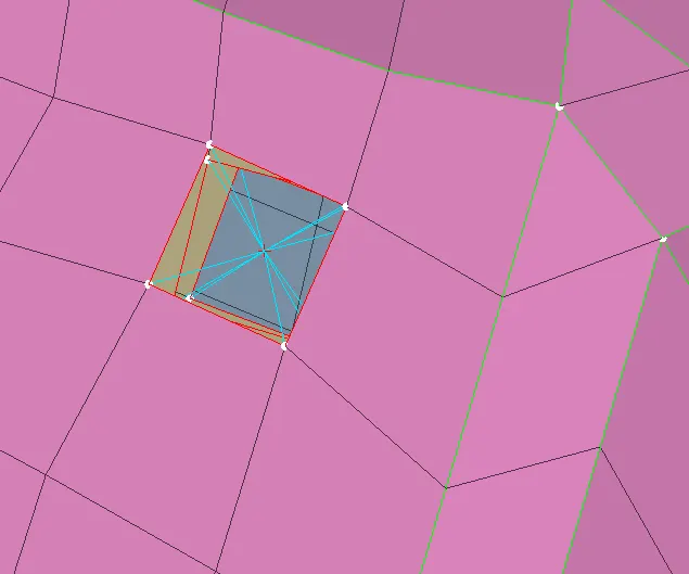
Fig. 14 RBE2 element used for connecting three surfaces.
Figure 14 shows that RBE2 elements were used for connections because it has hole provision, which allows us to rigidly connect all three surfaces.
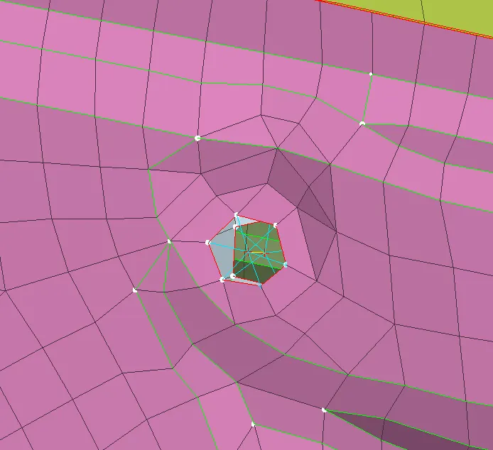
Fig. 15 Two Node RBE2 Connection.
There are two ways to provide rigid RBE2 connections. One uses Two Node RBE2 and the other Many Node RBE2. Figure 15 show Two Node RBE2 connection where two holes have separate RBE2 elements in blue color with Two Node RBE2 element in Yellow color. In this type, each hole has a separate Master Node and the Master Nodes of each hole are connected later. The two blue RBE2 elements were constrained rigidly by the Single Yellow line RBE2 element. Figure 16 shows Many Node RBE2 or Cluster RBE2 connections. In this type of connection both the holes are connected by a single Master Node. It looks like a cluster of flower petals, the so-called Cluster type or Many Node RBE2 connection.
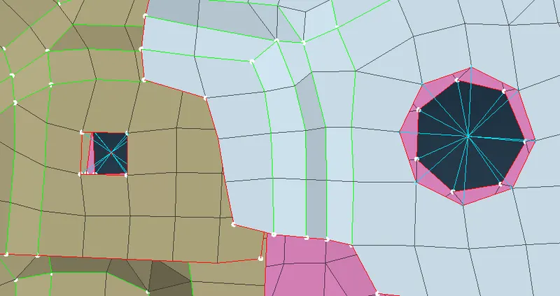
Fig. 16 Cluster or Many Node RBE2 Connection.
LEARNING OUTCOMES:
- Providing connections on an assembled model.
- Providing rigid to places where it is required.
- Assigning an appropriate Degree Of Freedom for the rigid elements to constrain their motion.
- Use of Spot weld to places where Bolt type of connection is not possible.
- Use of CBUSH elements for damping type of contact.
CONCLUSION:
A model is said to be successfully run, when all the components are meshed correctly, assigned proper thickness, and finally a good connection that ensures that all the parts in the model are constrained properly and rigids are provided at the required and necessary places.