Week 6 - Creating connection for Rear door
CREATING CONNECTIONS FOR THE REAR DOOR USING ANSA
Aim: - For the given FE model of car Rear Door, we have to apply PID’s to different parts and perform connections required, using NASTRAN deck and the Connection Manager.
Procedure: -
- To set PID’s to the various components of the Rear Door.
- To give connections at required places
- To use various element connections at various places by controlling the DOF.
- Giving stiffness and mass (in tons) to the required Elements.
Step 1: -
Applying PID’s: -
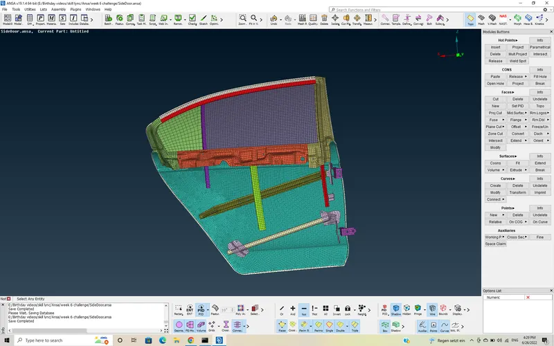
- To Apply PID’s, first we have to find the parts that are not attached to each other. Then, we have to isolate the part and select that part for applying PID. we have to use various options, to isolate the part, as we can’t use alone either PID option or options such as Macro, Entity.
>> So, I used different combination of commands such as, “!NOT ,+ Neighbor >> ALL / 1st Level” and “SET PID >> Feature (40°)” to isolate the parts.
>> After Isolating the parts,
Go to TOPO Module >> SET PID >> select the part >> NEW >> PSHELL >> Double Click.
>> Now, PID is applied to the part.
>> Follow the same procedure for all parts to apply PID’s.
Before Applying PID's
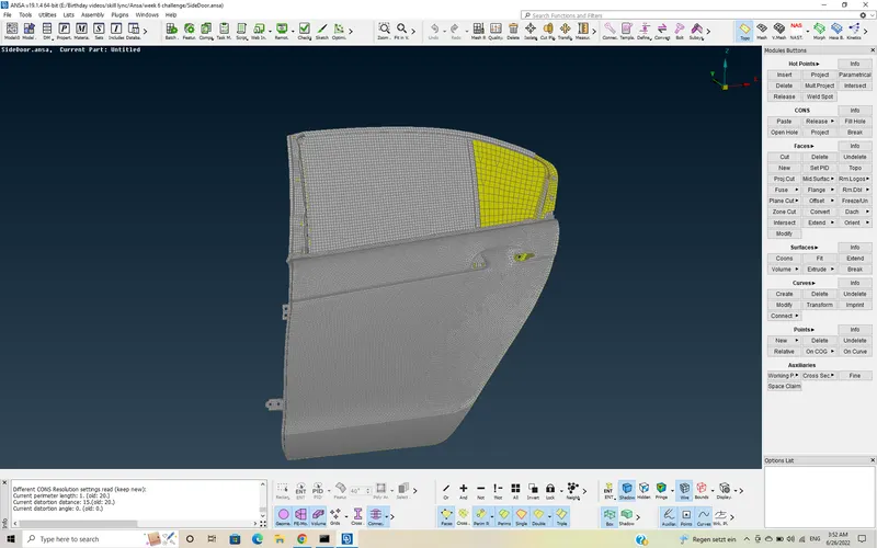
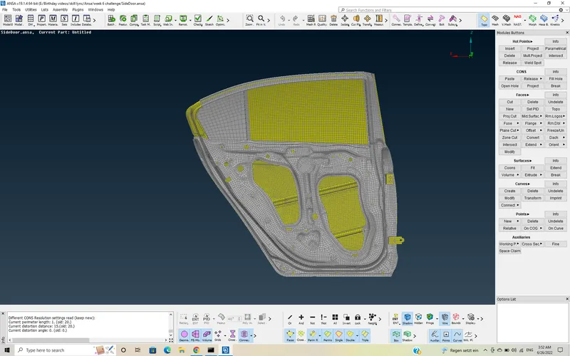
Isolating the parts
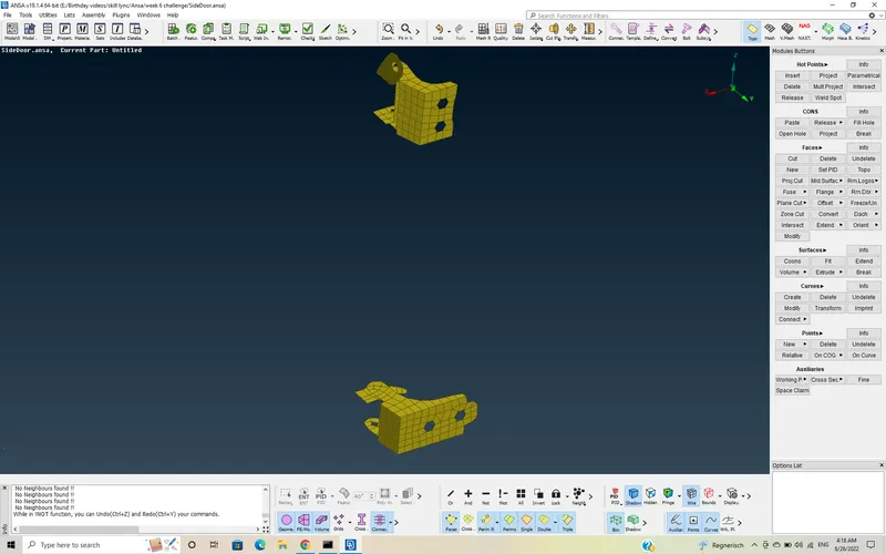
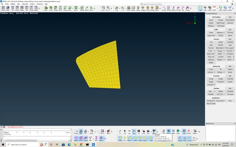
After Applying PID's
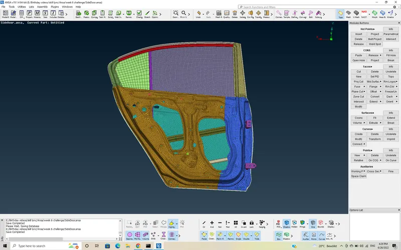
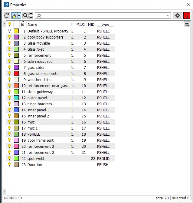
The PID's that are applied to the parts are shown below.
Step 2: -
connections:-
- Connections in ANSA are used to represent, mating between the parts in terms of FE model replacing the connections in Geometrical model.
- In ANSA, depending on the connections we have to give, we can connect the parts using, either the connection manager or the NASTRAN deck.
- Based on the material of the parts, and the type of connection(permanant fastening / temporary fastening) we have to make between them, the type of connections is decided. Different type of connections such as Bolt, weld, adhesive, rivets, rigids e.t.c are present in ANSA.
Rigid Connections:-
This rigid connections are made at the places, where the holes that are going to be used for connecting other parts are present.so, we use these at Hinge area also.
Here, we use RBE2 (Many nodes), to make rigid holes.
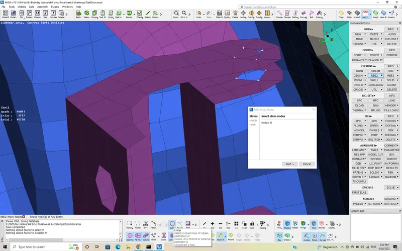
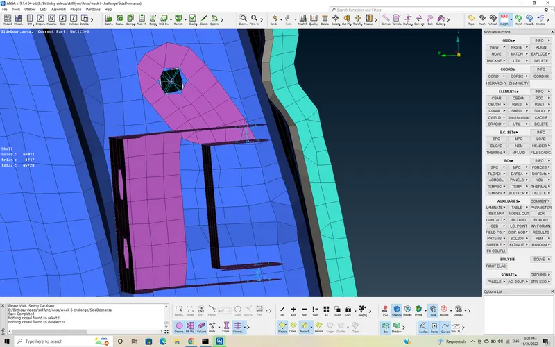
Now, connect the both rigid holes by RBE2(two nodes) element by constraining the DOF's and by allowing rotation in z-axis.
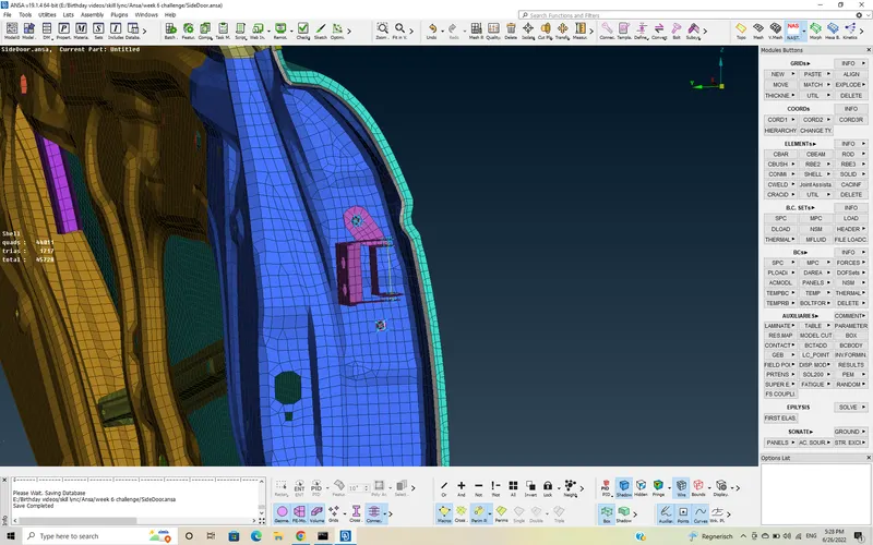
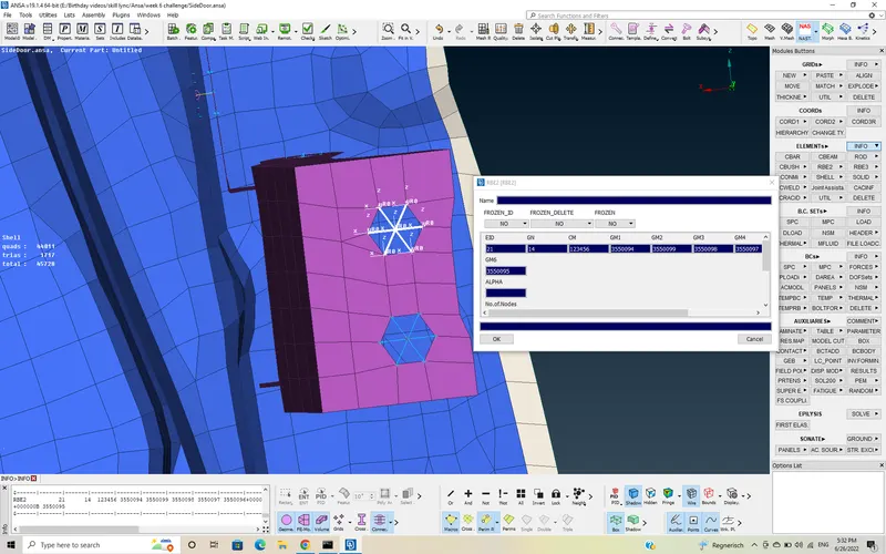
Here is the part of Hinge connecting to the car chassis, which should be rigid and we should restrict all DOF.
Bolt connection: -
To give the bolt connections, we need to have atleast two parts and a maximum of 4 parts to connect.
Bolt connections are given as follows:
create a 3D point using TOPO >> on COG >> and select the Middle part
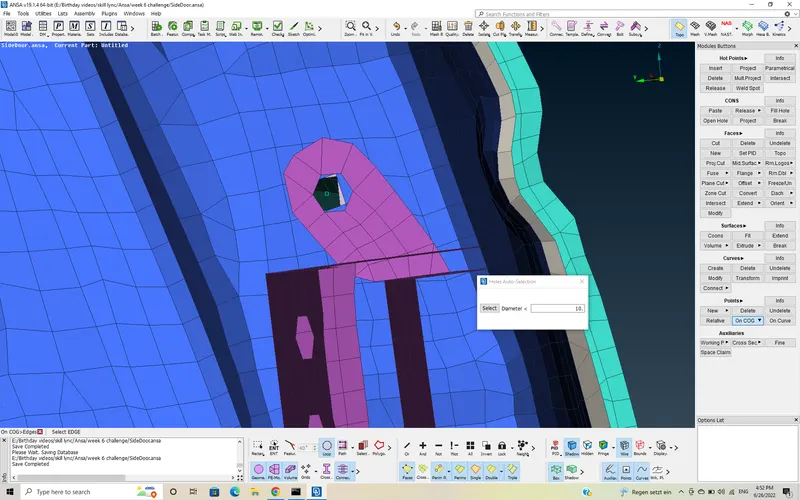
Now, select the 3D point and convert it to Bolt using select "3D point" >> convert >> 3D points >> Bolt
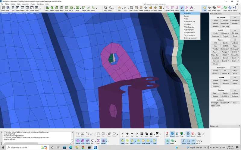
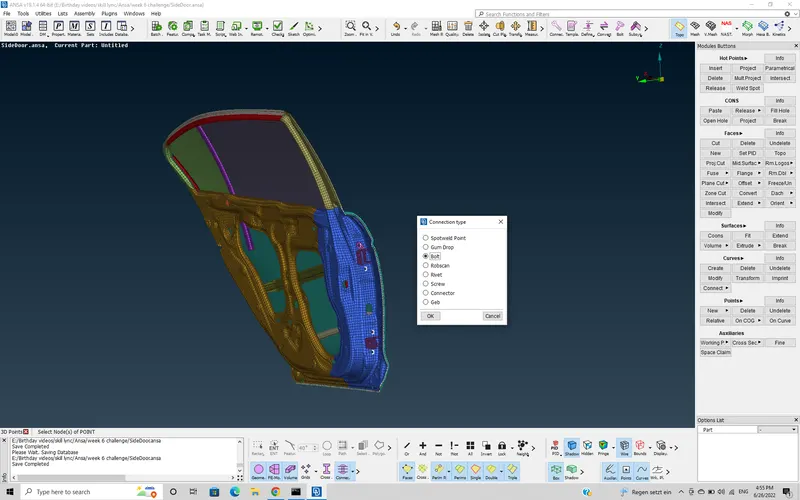
Now, a Bolt symbol is generated.
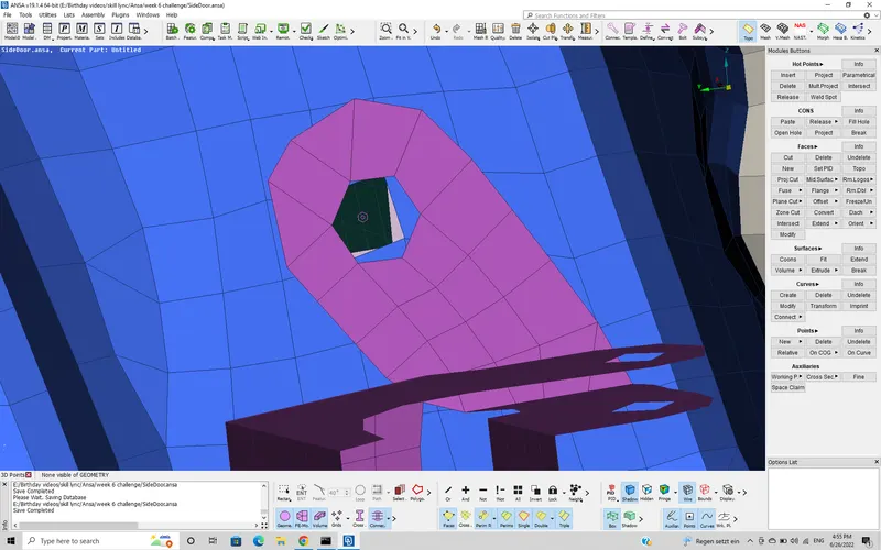
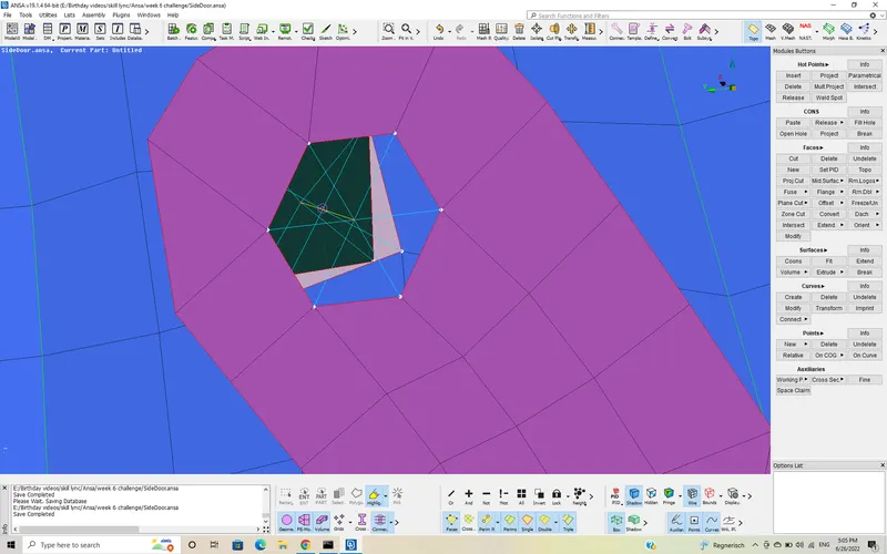
Now, we have to represent that bolt in terms of an element. To do that, we use connection Manager.
select "connection manager" >> box select the bolt >> middle click
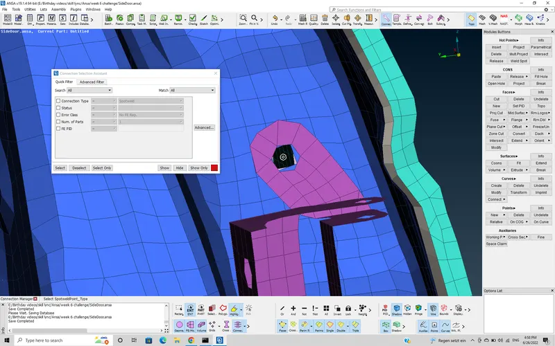
now, to make connections select the associated PID's as shown in figure using F1 button >> select PID.
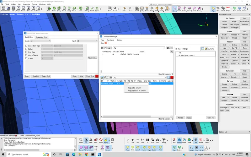
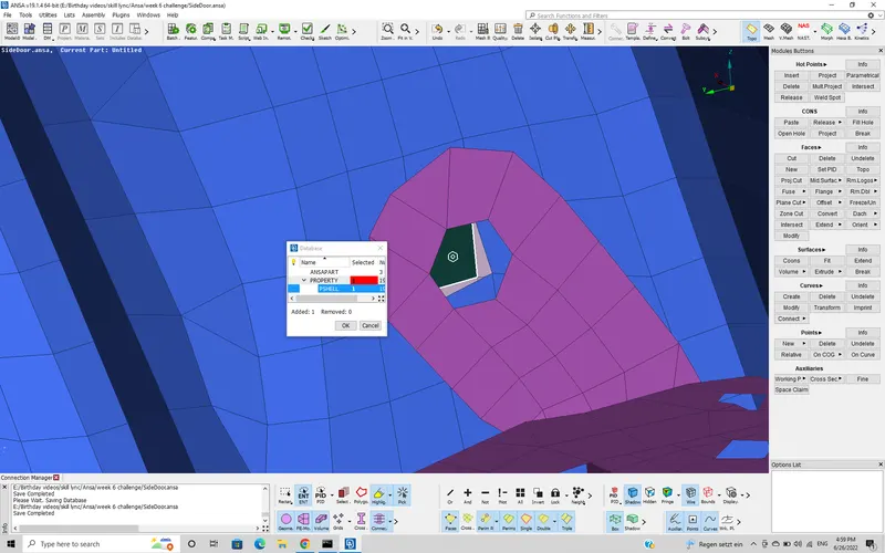
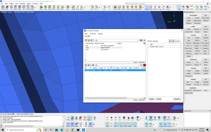
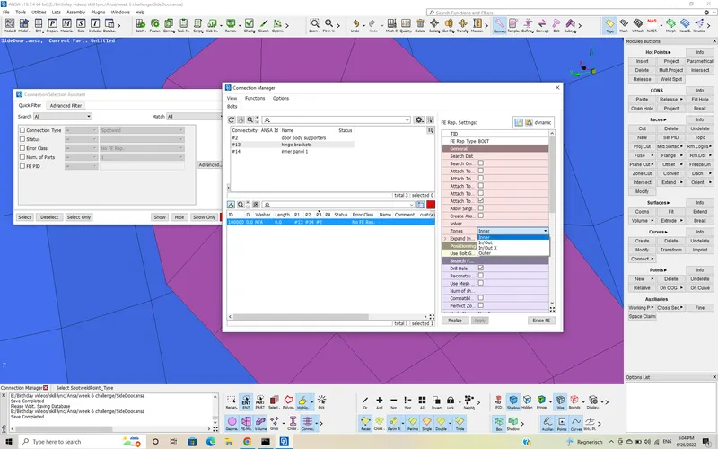
Now, select FE type >> Bolt >> select type of Zone >> apply >> realize.
The bolt connection is created.
SPOT weld connections: -
Spot weld connections are the permanant connections that are used to mate the parts rigidly . This connections are also made in the same way as Bolt connections but the type of FE element will be changed .
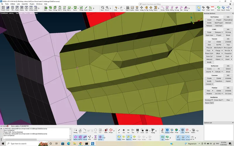
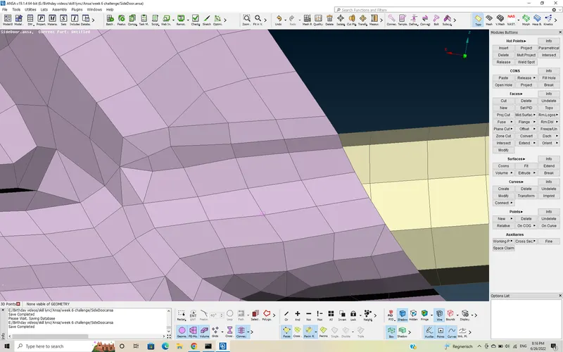
The Fe type used in the SPOT weld connection is RBE3-HEXA-RBE3
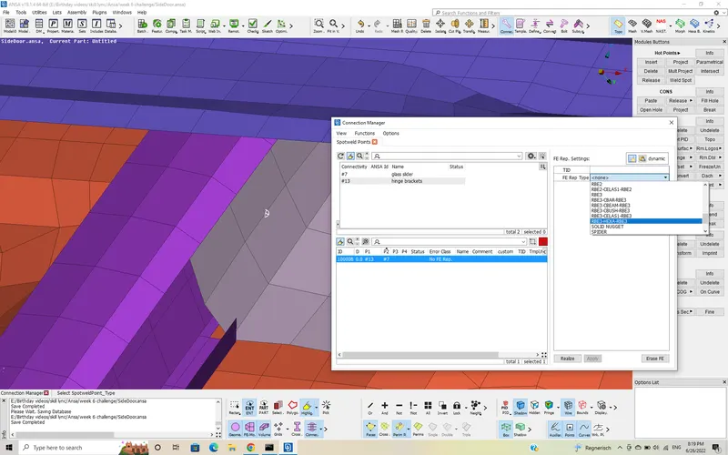
Now, the Pinflags are changed from 123 to 123456 to arrest all DoF's as it is a spot weld connection, and give a search distance to attach the connection. Also, create a PSOLID ID for the spot weld connections.
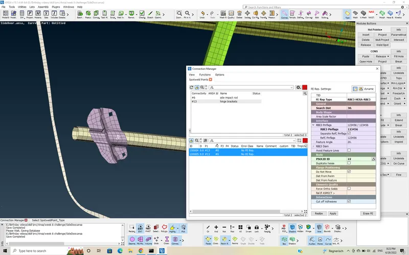
Now, click on Apply >> Realize . The element will be shown on the FE model
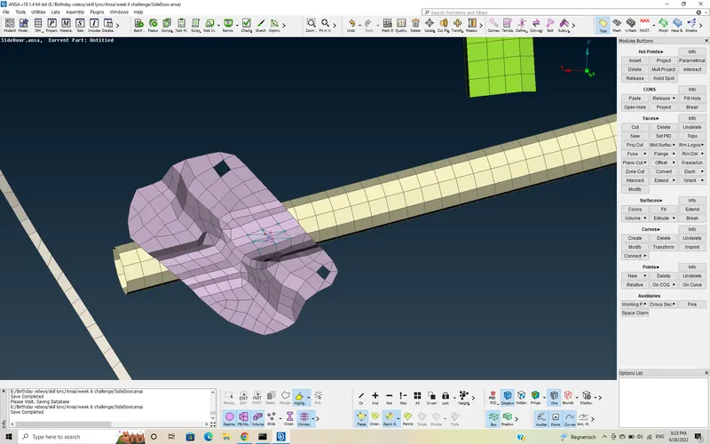
Handle representation:-
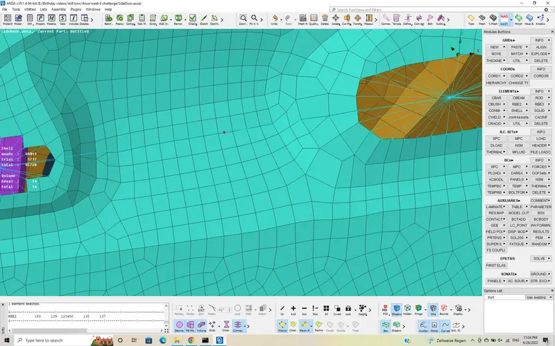
The Handle of the door is represented as Two rigid holes connected with a conecntrated Mass element.
The rigid holes are created using RBE2(many nodes) and also connected with same RBE2(many nodes).
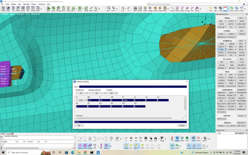
now, the mass is allocated to the node using CONMI >> CONM2 >> NODES.
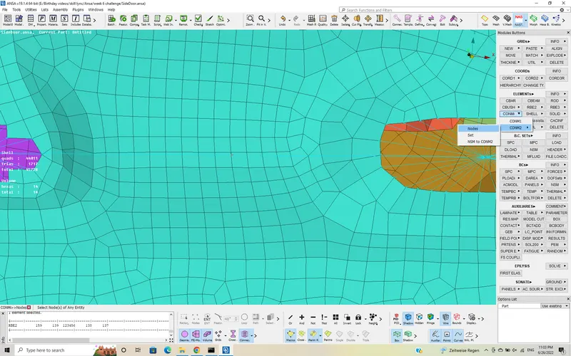
Now, the mass should be assigned in terms of tons in the dailogue box and click ok .
The mass is assigned.
connections for windows : -
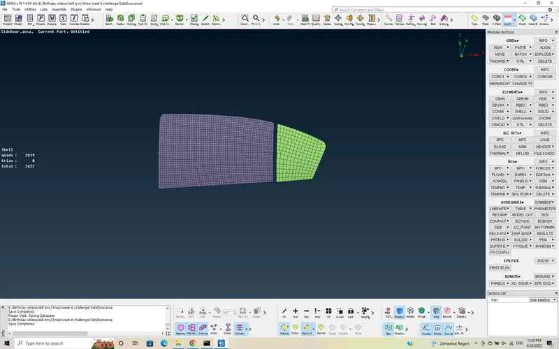
In rear door, we have total 2 windows, one is fixed on In and Out along all sides. The other is fixed only on bottom side and all the other sides are given only one side.
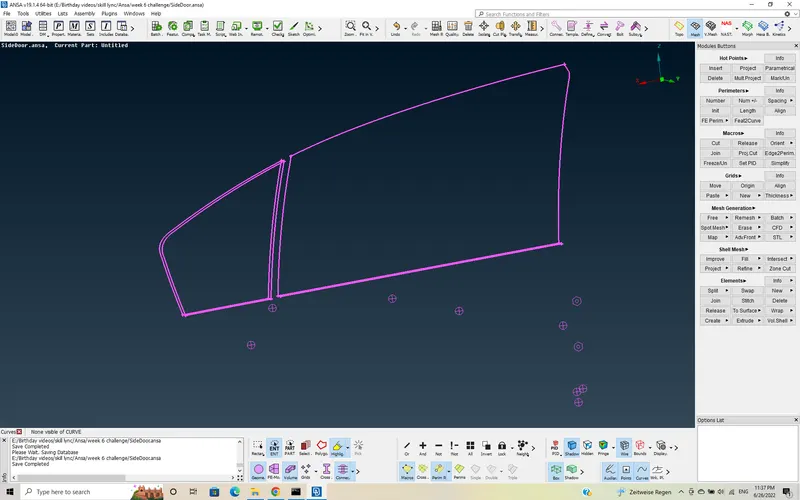
First isolate the windows, and create a curve using Mesh >> Perimeters >> FEAT2CURVE >> select elements using ENT >> Loop >> Middle click so all the circumference will be selected instead of selecting one by one element length.
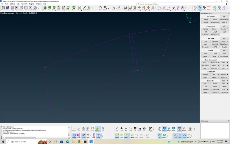
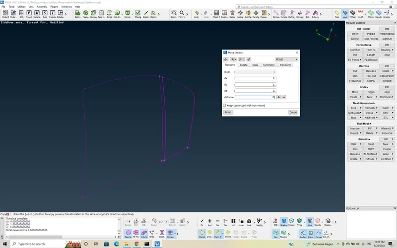
Now, move the curve feature on the other side also using Transform >> Move >> select lines to be moved >> dy = 1 >> distance = 10 assumed >> click on + >> Finish .
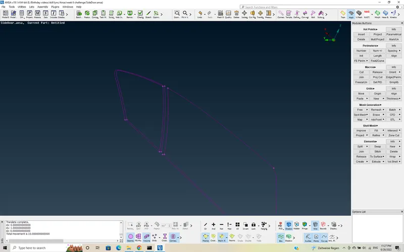
Now, these 3D curves are coverted into connections using convert >> 3D curves >> spot line >> ok
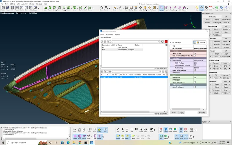
Here the weather strip is represented in FE model as RBE3-CBUSH-RBE3. Here the pinflags are only 123 a bit of rotation should be allowed inorder to not to lead the window to break. And the search Distance should aslo be given to connect the element with the neighbouring elements.
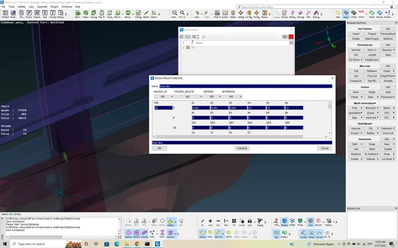
And a PBUSH ID should also be created by providing the stiffness in K1, K2, K3, K4, K5, K6. Now, click on Apply >> realize.
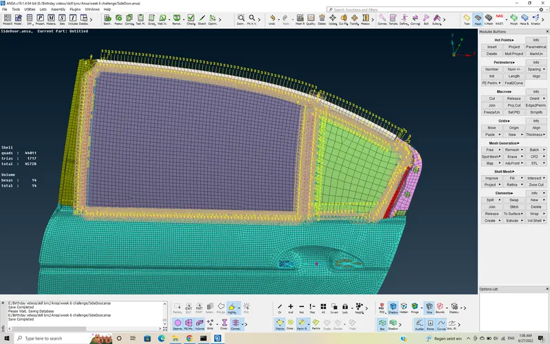
Now, the axis of created CBUSH elements are in local co-ordinate system that is according to element. Now, we change those axis of the elements to Global X, Y, Z axis .
Click F12 >> click on Geometry in Database dailogue box >> click on CBUSH>> activate "with Vector" >> select all elements >> Right click >> Modify
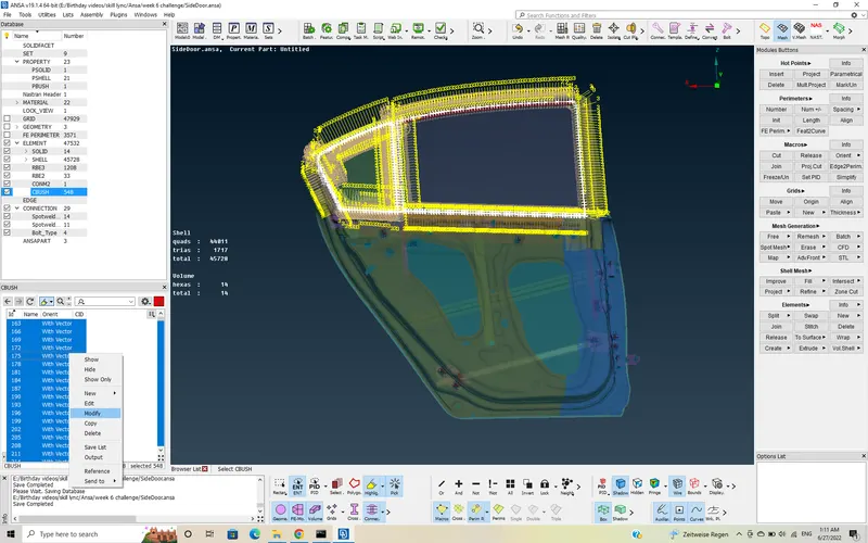
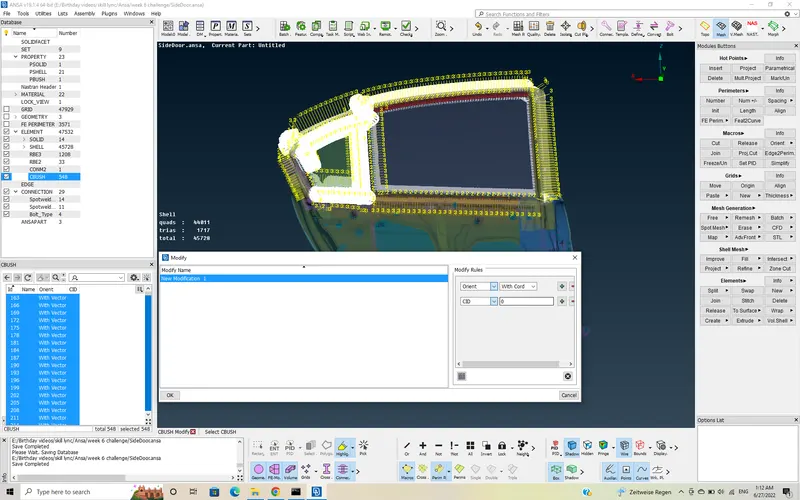
Now, we need to do 2 modifications , one is from Vector to cord . And the other is CID .
select Orient >> change to cord and then
CID >> enter "0"
click "OK"
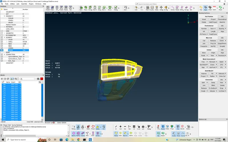
Now, we can see that all the elements are aligned to the Global axis.
Learning Outcomes:-
- Learnt to apply PID's to a FE model
- understanding and applying the connections such as Bolt, rigid, CBUSH, Spot weld.
- Leant to represent a part as a concentrated Mass such as Door handle.
- Alignment of the CBUSH elements
- Understanding the elements such as RBE2, RBE3, RBE3-HEXA-RBE3, RBE3-CBUSH-RBE3