Week- 5 - Solid meshing
PREPROCESSING OF REAR VIEW MIRROR (SOLID MODEL) USING ANSA
Aim: - For the given Rear view Mirror (a solid model), we have to clear the Geometrical errors that are present in the model and have to perform Tetra-Meshing on the Model using ANSA.
Procedure: -
- Performing Geomentry checks
- Geomentry cleanup such as Error removal, Fillet removal etc.
- Deploying surface mesh/ shell mesh without off elements
- Defining Volumes
- Deploying volume mesh/ solid mesh without off elements
Step 1: -
Basic checks of Geometry: -
- First, we will import the CAD Geometry to ANSA and will check whether the CAD model format is in supportable format or not. Supportable formats are
STEP (*. STEP/ *.step/*.stp/*.STP)
IGES (*.IGES/*.iges/*.IGS/*.igs)
STL (*.stl)
- Second, we have to ensure that the dimensions of all parts in the model, importing in ANSA must be same, and it is recommended to be in mm.
- Most important thing is graphics check. Here we have to ensure that the Hot points and CONS are clearly visible and no problem should be there in visibility. If problem is there, we can put this command “-performance_mode 3”, in the popup box while opening ANSA to get good Graphics.
TIP: - If we need to get Good Resolution of the hot points, do the following
Click F11 >> Go to Presentation parameters >> scroll the bar of “all details” to left >> click on apply
Step 2: -
Geometry cleanup: -
- First, we have to assign the material to the given model without letting any problem to arise further. Here, assigning means nothing but just ticking the box of the created material in MID tab.
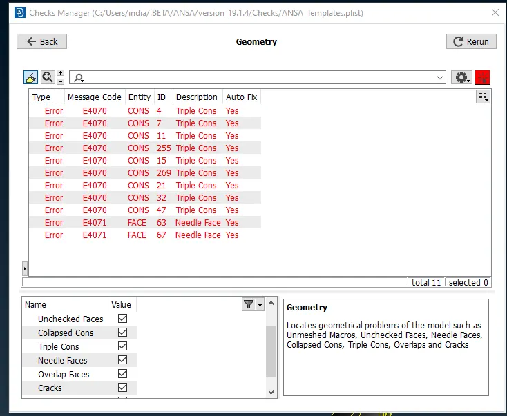
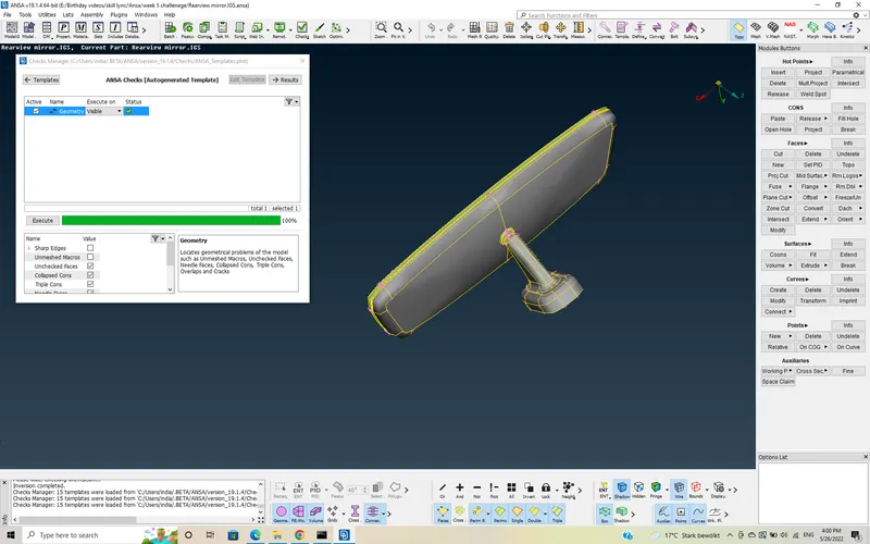
- Now, we have to perform checks on the geometry using “checks” Geometry checks are, checking for Single cons, triple cons, cracks, needle faces, collapsed CONS, unchecked faces.
Go to checks >> Geometry >> select checks to be performed >> Execute
- Before Geometry cleanup
- After Geometry cleanup
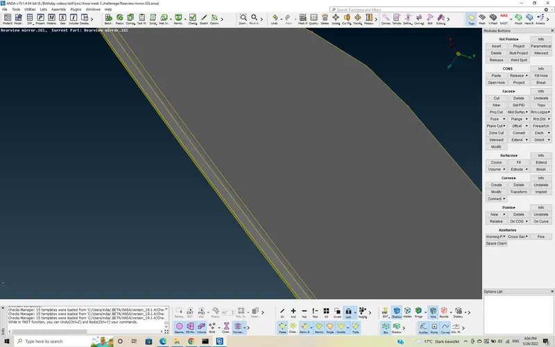
- Now, we will remove the fillets in some regions using DACH option.
Before Fillet Removal: -
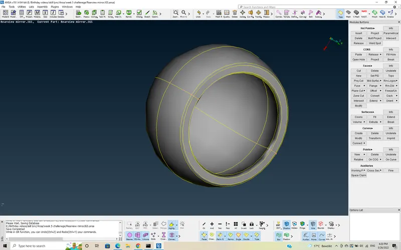
- After Fillet Removal: -
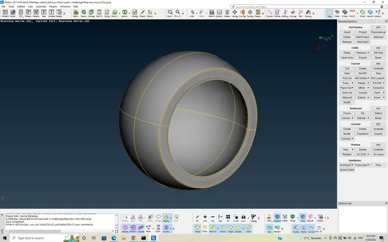
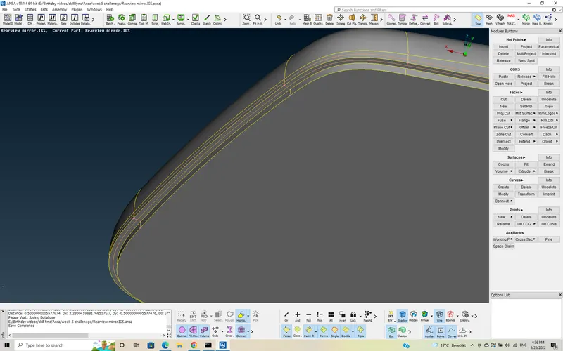
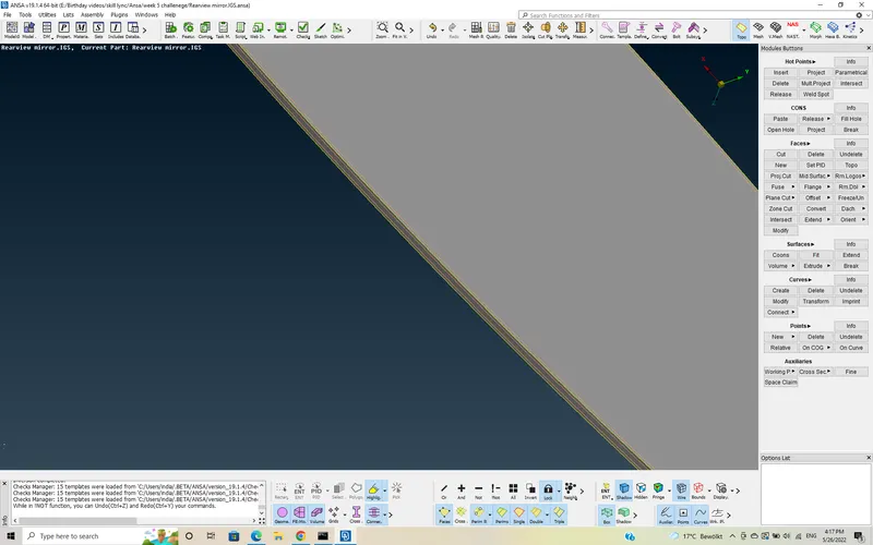
- Supressing some feature curves/ Defeaturing to obtain better Mesh flow
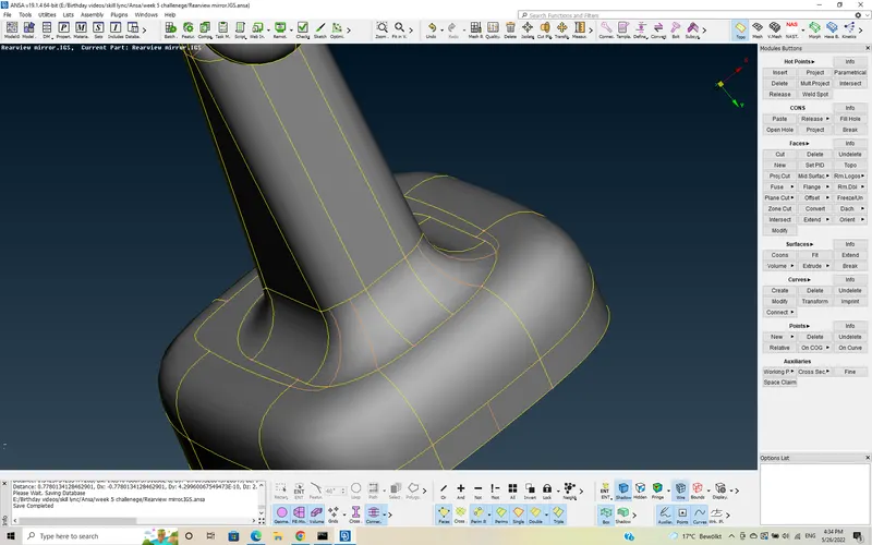
- In this Rear view Mirror, we have 4 components. For better access of this components while meshing and other operations, we will create locks for each and every component by isolating them one by one.
Step 3:-
Deploying Shell Mesh: -
- Before meshing also, we have to check for the geometrical errors and has to do basic things such as, performing Geometry check, surface orientation. Only after having zero errors, we have to proceed for meshing.
- We will perform meshing using "Spot Mesh" on the surfaces of components one by one, which already stored in locks.
- We have to follow the Quality criteria given in the question.
| Quality Criteria | Value |
| Target/Average Length | 1 |
| Minimum length | 0.5 |
| Maximum Length | 2 |
| Tet Collapse | 0.2 |
- Mesh Parameters
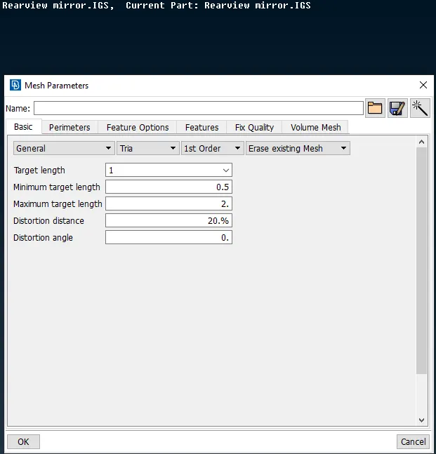
- Quality Parameters set for shell Mesh
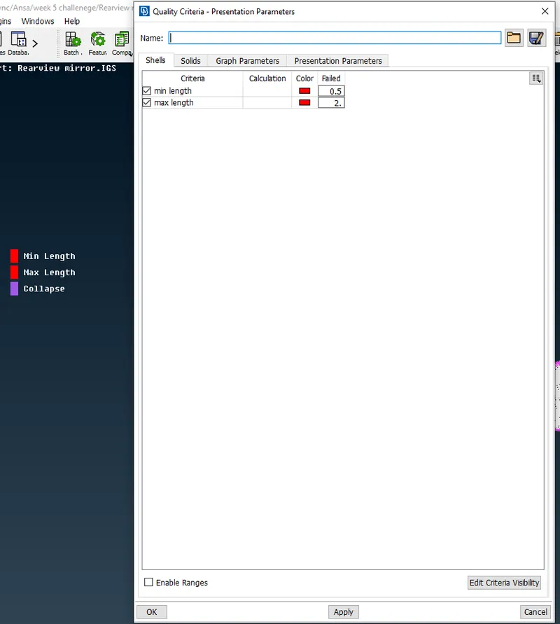
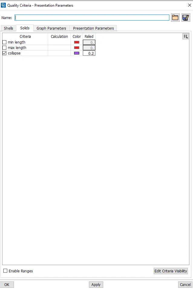
- Now, we will start Meshing . During Meshing, we will use spot Mesh . We use Ortho Tria's on curved surface and Tria's on Plane surfaces . We are using two different element meshes inorder to capture the features without any raise and dents in surfaces.
- Goto shell Mesh >> spot mesh >> Ortho Tria >> Mesh the curved surfaces.
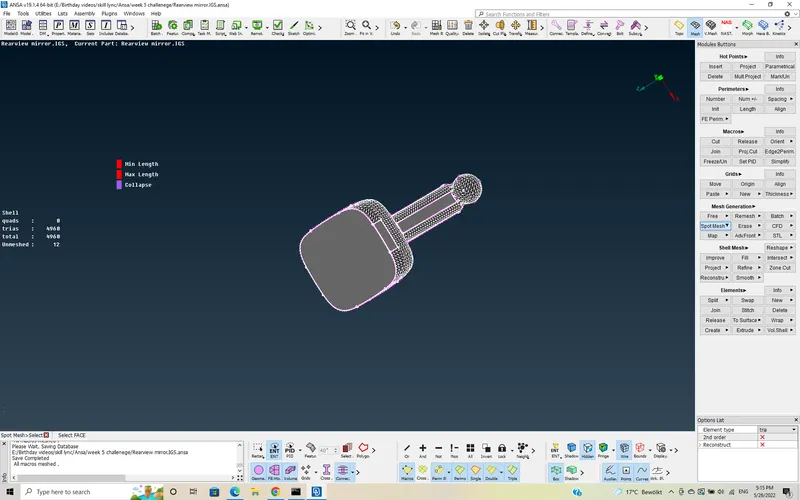
- So, we will mesh each and every part and remove the errors using options like, Reconstruction, Remesh, Number +/- .
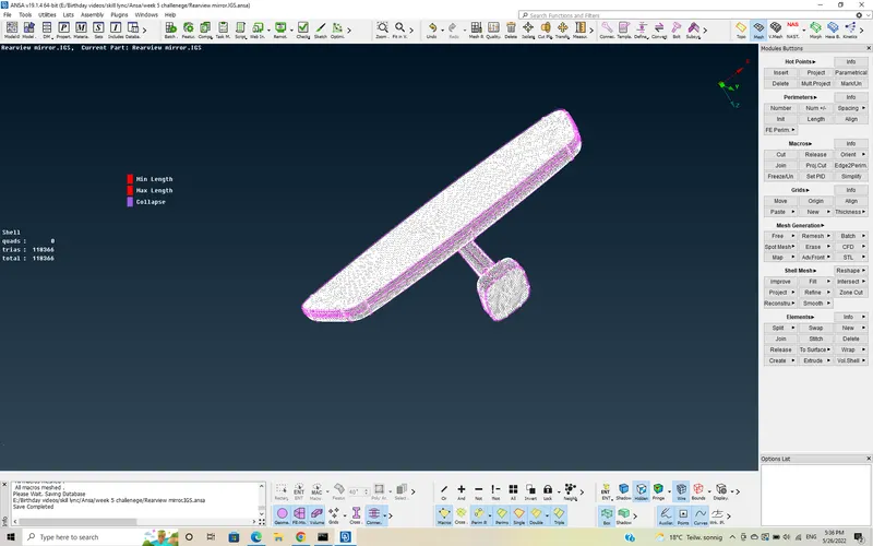
- This is the part after shell Meshing.
Step 4: -
Solid Meshing/Volume Meshing: -
- Inorder to perform solid meshing, first we need to ensure the volumes are closed and then we have to Define the volumes.
- For Defining Volumes
Goto Define >> Manual >> select componenet >> Middle Click >> New >> PSOLID >> Apply.
- we have to do the above procedure to all the components in the part.
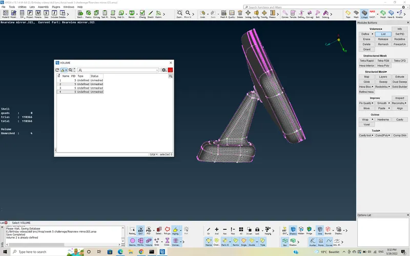
- If you see the above image, it shows the volumes that are defined and it also shows, the meshtype is undefined and status is unmeshed as they are just defined.
- Now, We will Mesh the volumes using Tetra-FEM option. I use Tetra-FEM option, as it is mostly suited for structural analysis applications.
- Now goto Unstructured Mesh >> Tetra-FEM >> select voumes >> Middle click.
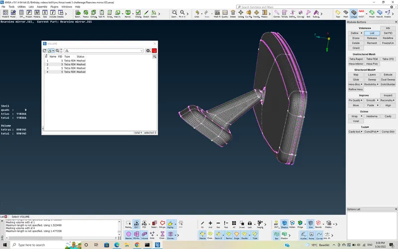
- Here in the image, we can see the Meshtype as Tetra-FEM and status as Meshed. so, all the compnonents are solid meshed.
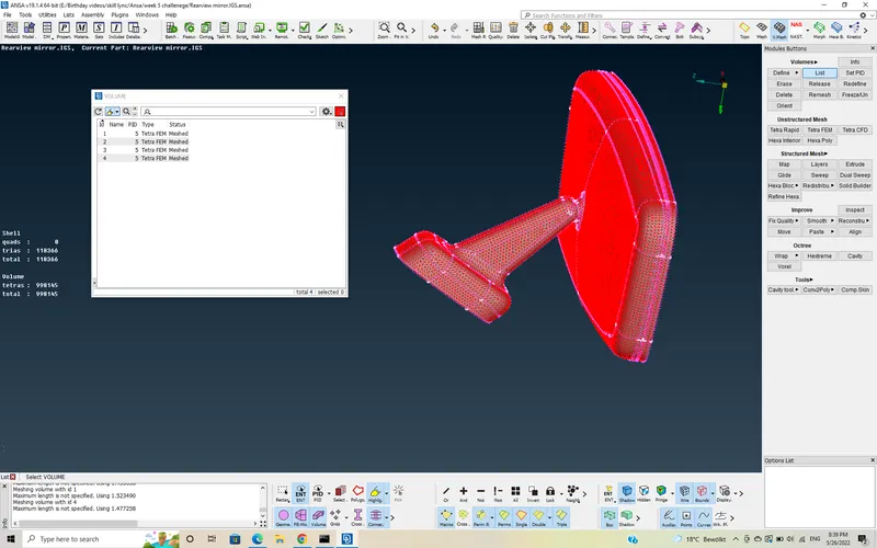
- If we switch on the Boundary option, we can see the all the components in Red lines, this resembles the components that are solid Meshed.
- Now, we will do a sectional view of the part and see , how unstructured the Mesh is.
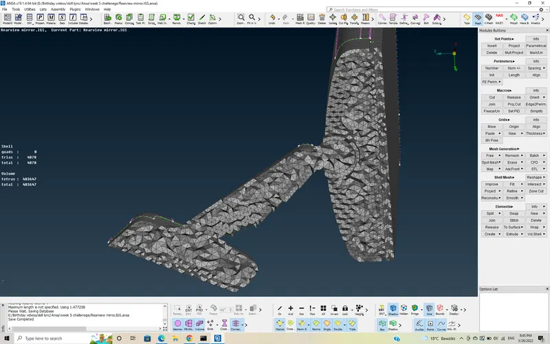
- As we can see, it tries to build a structured Mesh for first one - two rows from the surface mesh, but later on it will become unstructured in roder to fill the volume of the componets . This is why it is called as unstructured.
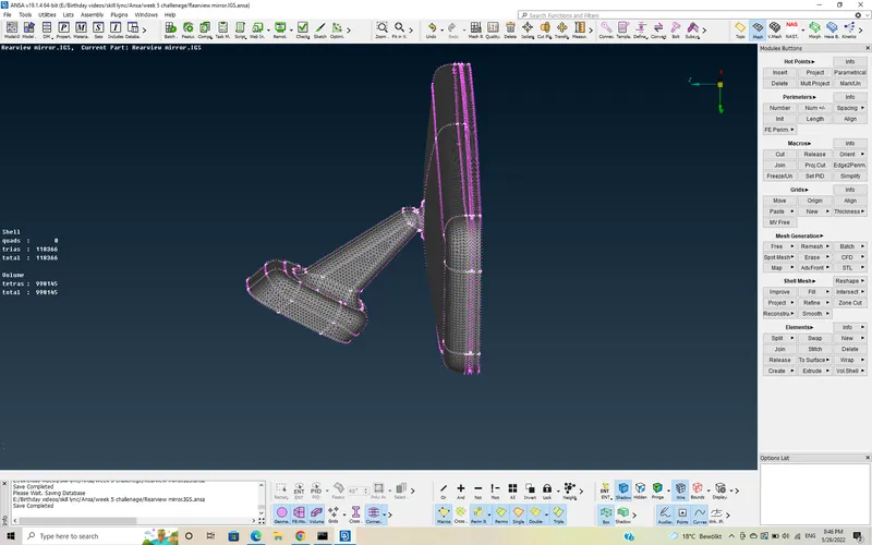
- Here I will attach the Final Solid Meshed rear view Mirror.
Learning outcomes: -
- Knowing the GUI of Volume meshing
- To practice the commands in Volume Meshing >> unstructured Mesh module.
- Defining volumes and and creating PSOLID property.
- To know handling the off elements with tet collapse.
Conclusion: -
- Removed the Geometrical errors
- Deployed shell and solid Mesh without any off elements.