Week 6 - Creating connection for Rear door
- Aim: For the given Car Rear Door FE model, create and apply different PIDs for different components. Perform suitable connections like bolt or weld connections without thickness assignment to the given FE.
- Methodology:
1. Importing the FE model into the ANSA environment.
2. Checking the FE model for any discrepancies/ Separating the FE model into different lock views.
3. Applying PIDs to different components of the given FE model.
4. Deploying appropriate bolt, weld, and other connections on the given FE model.
5. Ensuring appropriate degrees of freedom to the connections.
- Detailed Procedure:
1. Importing the FE model into the ANSA environment.
Fig. 1: Imported FE model
2. Separating the given FE model into different Lock views for better access during the connection process.
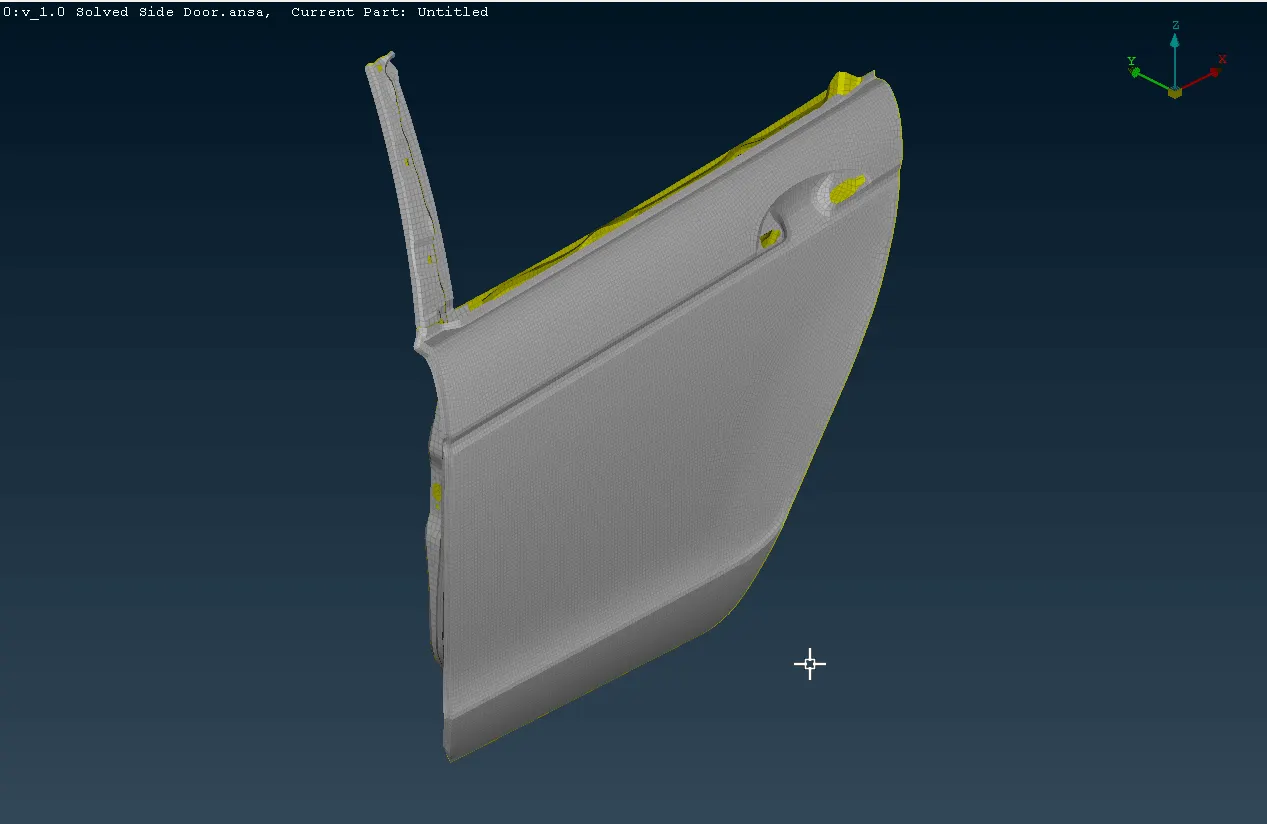
Fig 2.a: Door Shell FE model
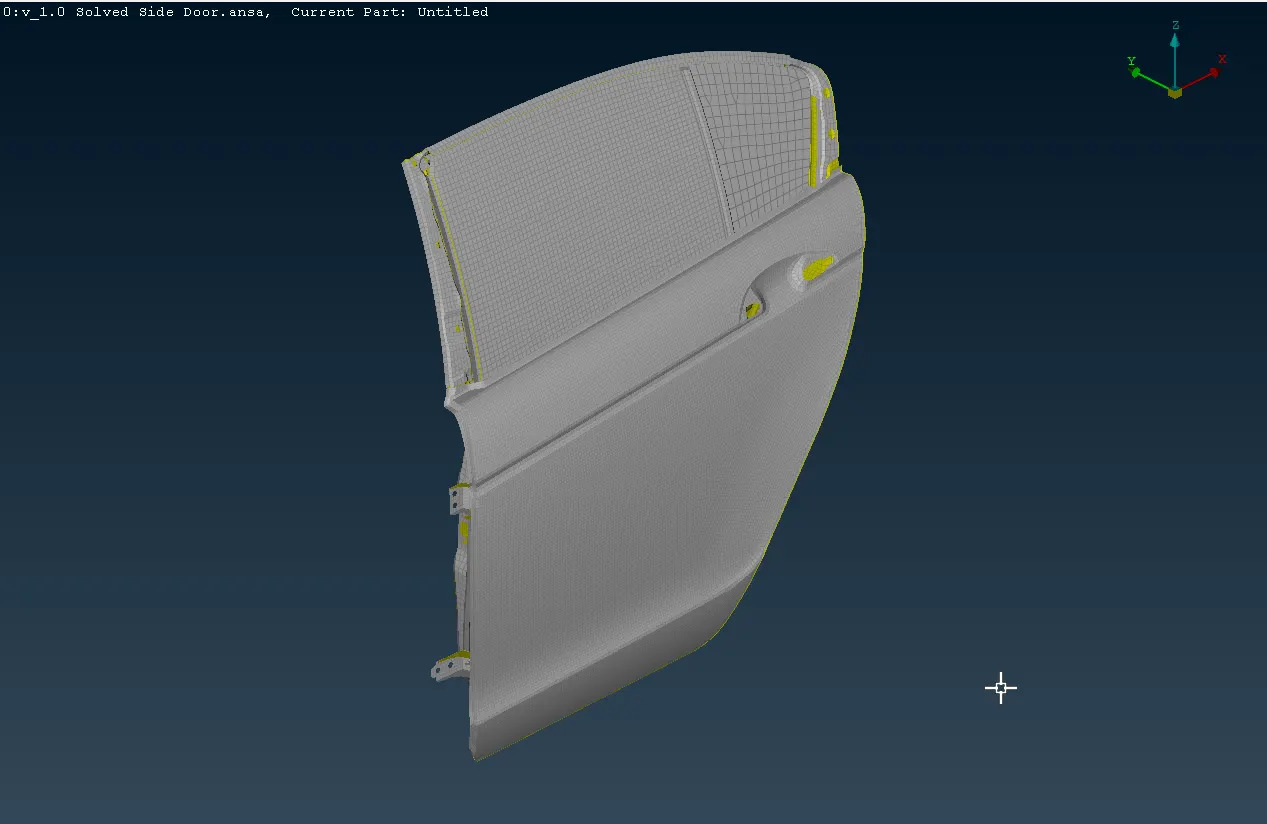
Fig 2.b: Inner strengthening cross members FE model
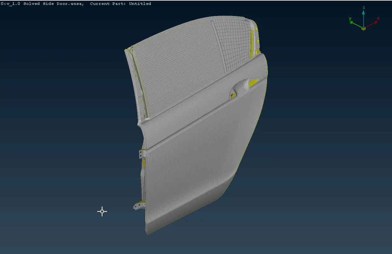
Fig 2.c: Window sliding mechanism FE model
3. Applying PIDs to the mid-surfaces of different component parts.
This is done in order to better distinguish between various components in the assembly so that appropriate connections can be deployed between those components.
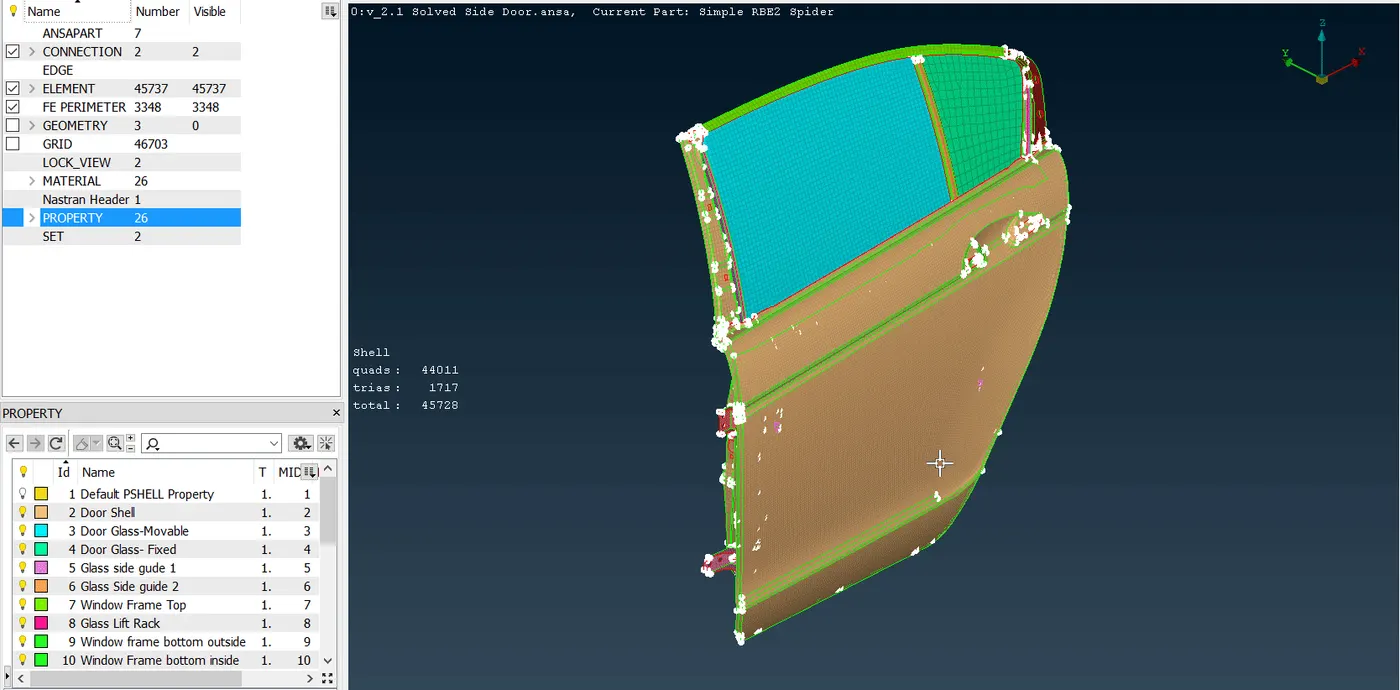
Fig 3: After application of PIDs to all the components of the given model
4. Making the bolt connections for different components.
- There are various techniques for deploying bolt connections. The point to note here is that a bolt connection essentially constrains all degrees of freedom to the components that it is connecting. So, it is correct to say that we are constraining two or more components in all degrees of motion when we deploy a bolt connection to them.
- In ANSA, one of the types of element that is used for a bolt connection representation is called a Rigid Body Element of type 2 or RBE2.
- The most basic form of representation of a bolt connection is explained as follows.
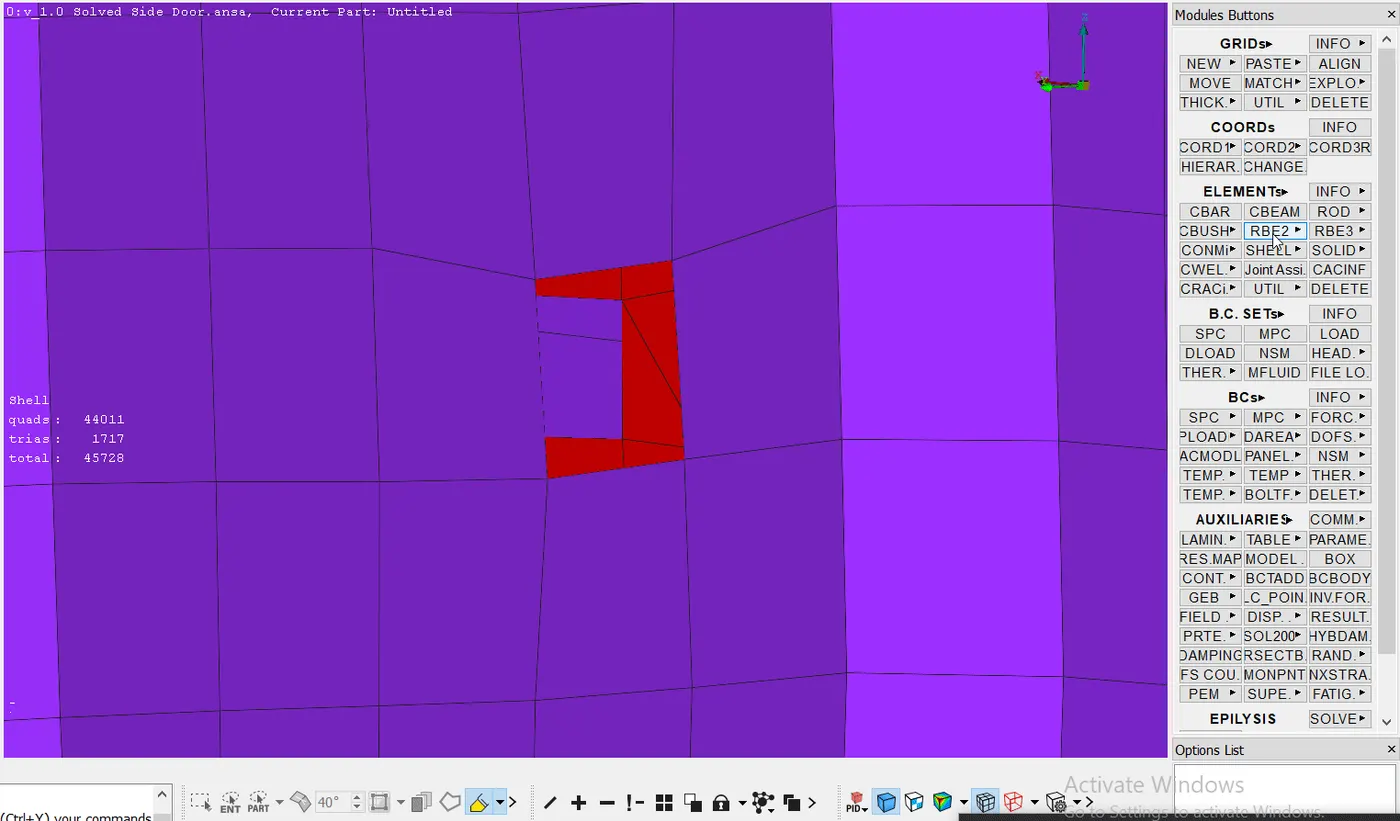
Fig 4.a: Creating a simple RBE2 spider
- Fig 4 shows the process of creating a simple RBE2 spider which is further used to create the complete bolt connection with the other part. For this, we use the RBE2> Many Nodes function under the Elements block in the Nastran Deck.
- We then select the nodes at the boundary of the hole and create the RBE2 spider with all DOFs constrained. We also assign this new connection/ RBE2 to a new part and name it something relevant like "Simple Spider RBE2' as seen in fig 4. We may also add this to a new part group for easier access later on in the project.
- We can follow the same process to create the RBE2 spider on the hole of the adjacent part as well.
- These spiders represent the bolt head and nut that are in contact with the surfaces of the two parts to be bolted together. The bolt stem is represented by another type of RBE2 element called a Two Node RBE2. It is created using the following steps.
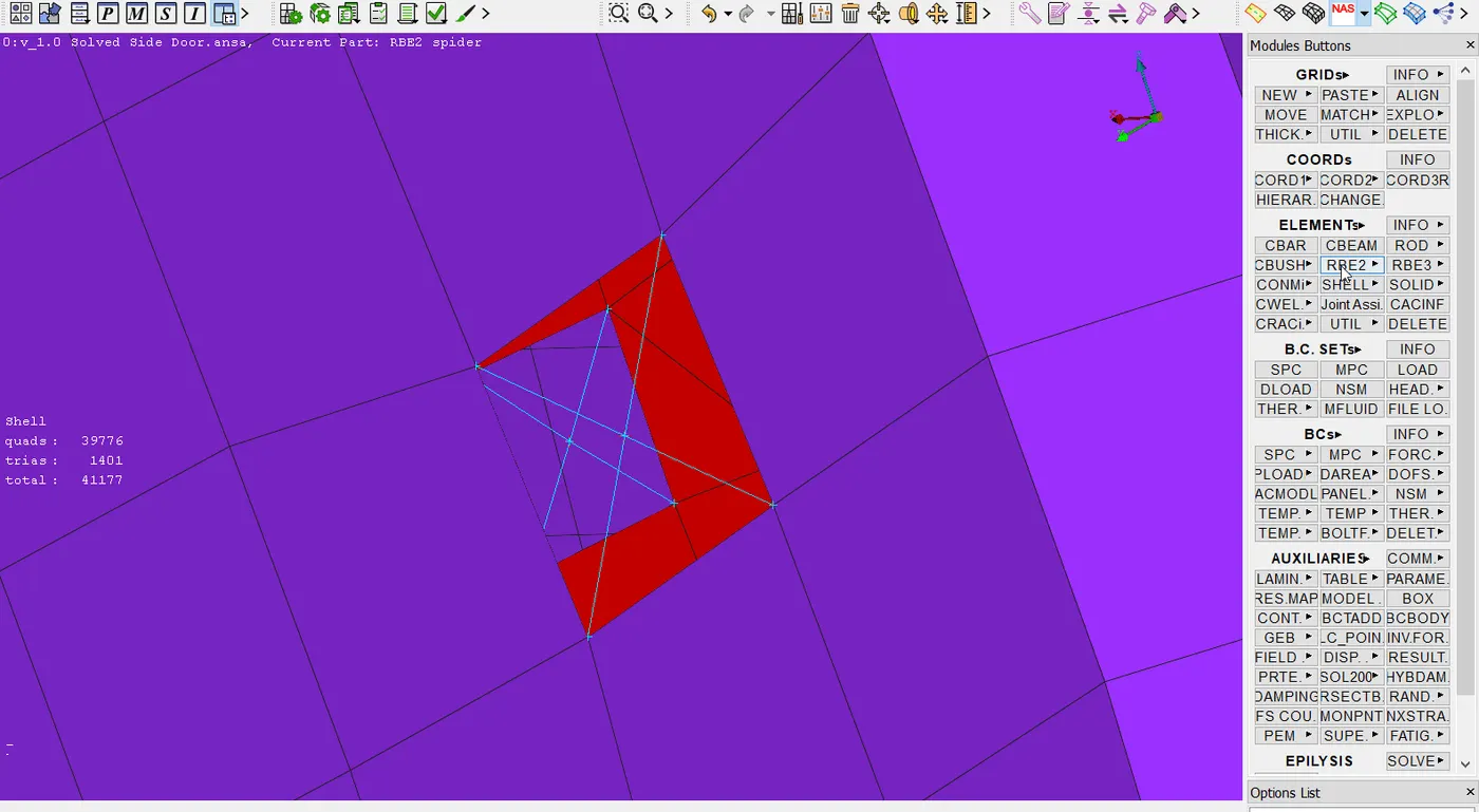
Fig 4.b: Creating a bolt stem representation using Two Node RBE2
- We create the bolt stem representation by using the RBE2> Two Nodes function in the Elements group. We then select the two nodes at the center of the two spiders previously created and finally name the PID for the created Two Node RBE2.
- There is another bolt connection representation called a Cluster RBE2 representation for bolt connection. The following process can be followed to create this type of bolt connection representation.
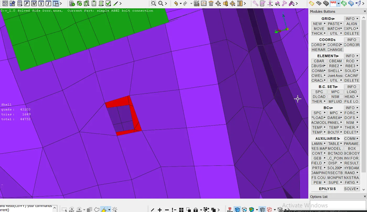
Fig 4.c: Creating a Cluster RBE2 for bolt connection representation
- To create a cluster RBE2 we use the Many Nodes RBE2 function and select the nodes of both the components that are to be connected using the bolt connection.
- The main difference between the two types of connection representations is that a cluster RBE2 does not have a bolt stem representation however both can be used to completely constrain all degrees of freedom.
- Since, a bolt connection, among other types of connections is commonly used in many cases, ANSA comes with preset connection tools that minimize the time required in the connections phase. We can thus create a 3D point where a bolt connection is to be realized and then using the connection manager deploy the connection by selecting the parts by their PIDs as seen below.
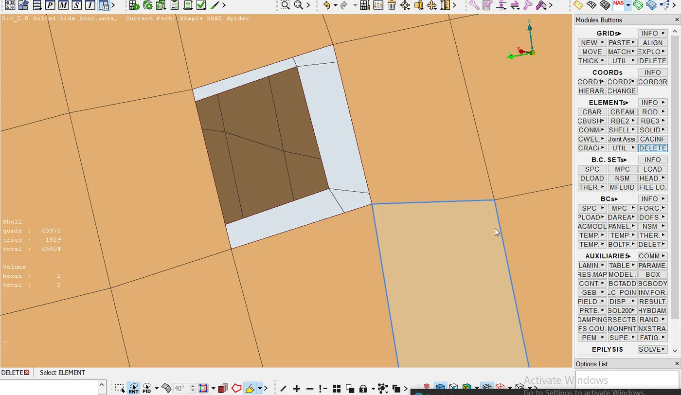 Fig 4.d: Creating a 3-d point for deploying a bolt connection
- In fig 4.d, a 3D point is created where there is supposed to be a bolt connection. To do that we use the Points> On COG> Points function and select the nodes on the perimeter of the hole.
- Then we use the Assembly> Convert function to convert the 3D point into a bolt connection, after which we use the Connections Manager to realize the bolt connection by selecting appropriate PIDs and providing different parameters for the connection, as seen below.
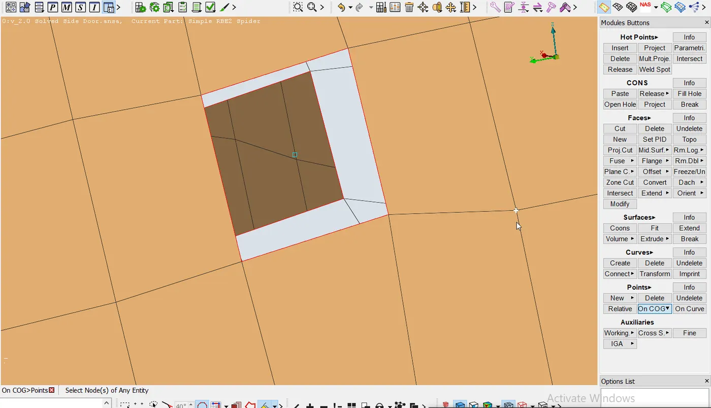
Fig 4.e: Converting the 3D point to Bolt connection and realizing the same
- This technique is the fastest among all discussed before.
5. Making the pin connections (bolt connections with one free DOF) for the door hinge brackets.
- Here, it is to be noted that the pin connection allows rotation about its axis so while deploying the bolt connection we have to constrain just 5 degrees of freedom.
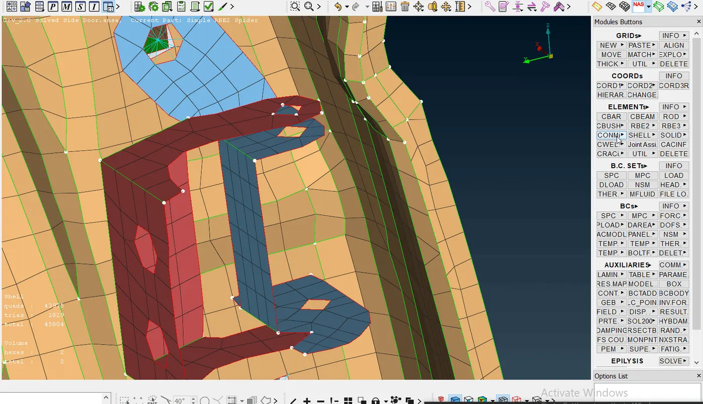
Fig 5.a: Creating a Cluster RBE2 for pin joint
- The thing to note as seen in Fig 5 is that the degrees of freedom that are constrained are 12345 meaning one rotational degree of freedom about the Z-axis is left free thus allowing the connected components to move about the same. We need to create a similar cluster RBE2 for the lower holes for these brackets and then connect the master node of these two cluster RBE2s with a Two Node RBE2 with a rotational degree of freedom about the Z-axis free.
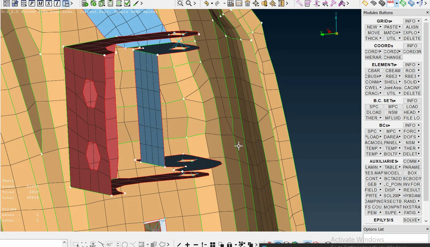
Fig 5.b: Creating the Two Node RBE2 for the pin joint
- We create a similar pin connection for the bottom brackets as well.
6. Now we create the seam weld connections on the inside of the door shell with the strengthing member.
- To do this, first, we create a curve at the edge of the member which is to be welded to the door and then convert that curve into a seam line. This is done by using the Perimeters>Feat2Curve function in the Mesh module. Note that Path selection is used for ease.
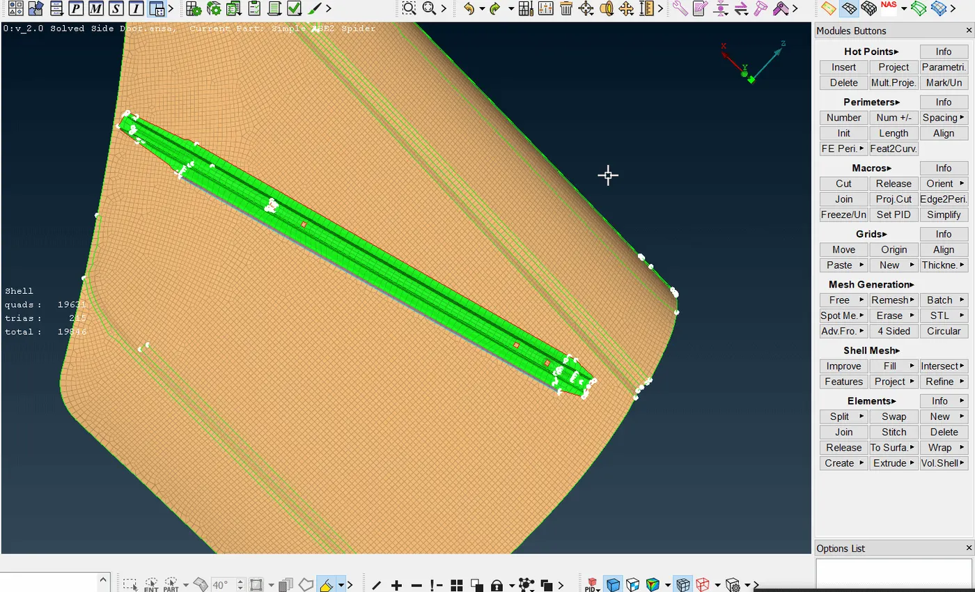
Fig 6.a: Creating a curve for the seam weld and converting it into a seam line.
- Then, we use the connections manager to deploy the seam weld connection after providing the appropriate parameters for the same. We select the P1 and P2 by considering what the base sheet is and use the OVERLAP-SHELL type of FE Rep Type. Then we provide a search distance, specify the base sheet, specify the width by an 45deg angle, and finally realize the FE.
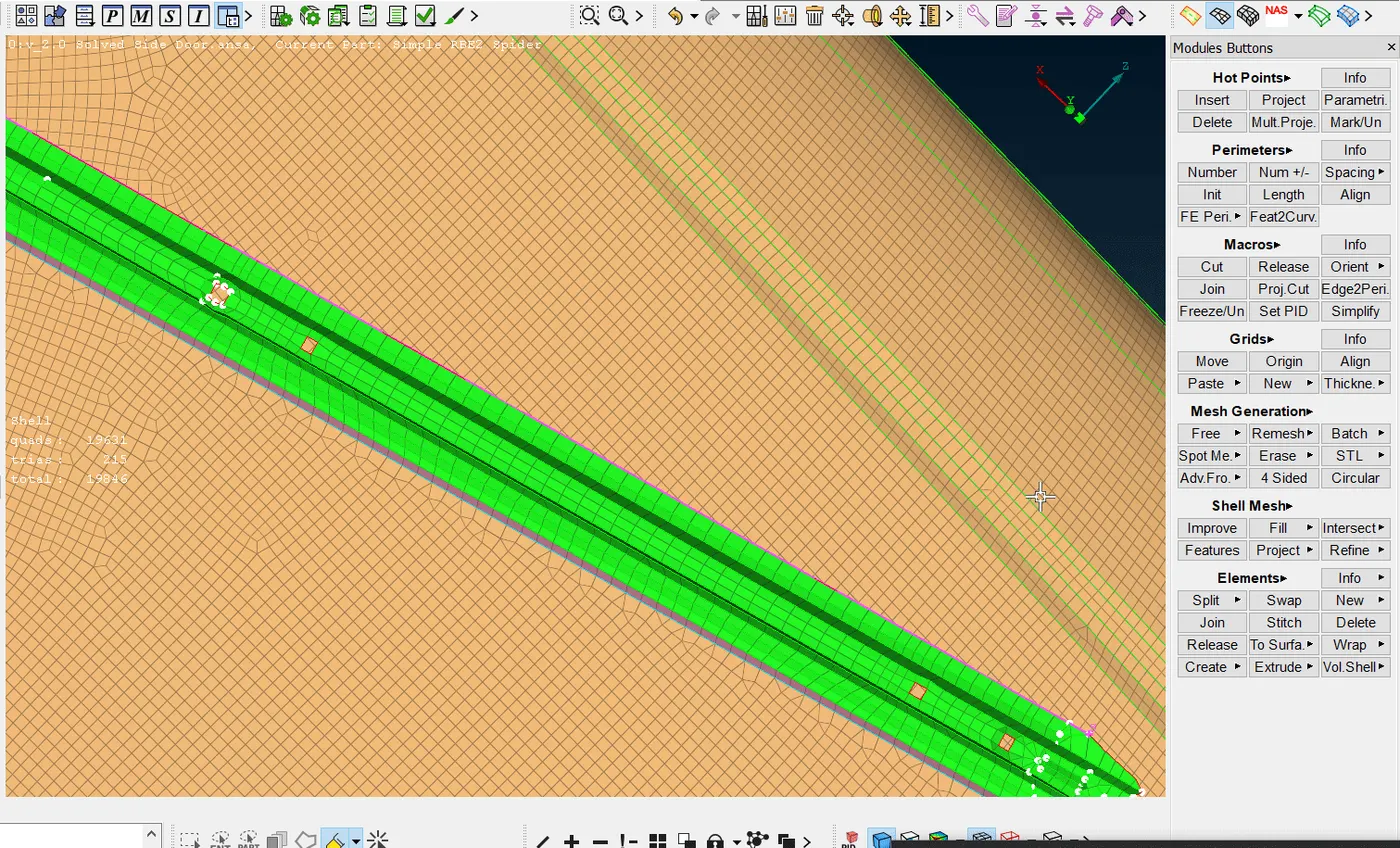
Fig 6.b: Providing the parameters for the seam weld connection and realizing the seam weld FE
7. Now we can start making the rubber bush connection between the window glass and the frame, also called as a CBUSH element.
- The process is similar till Step 6.a after which we convert the curve into a Spot Line.
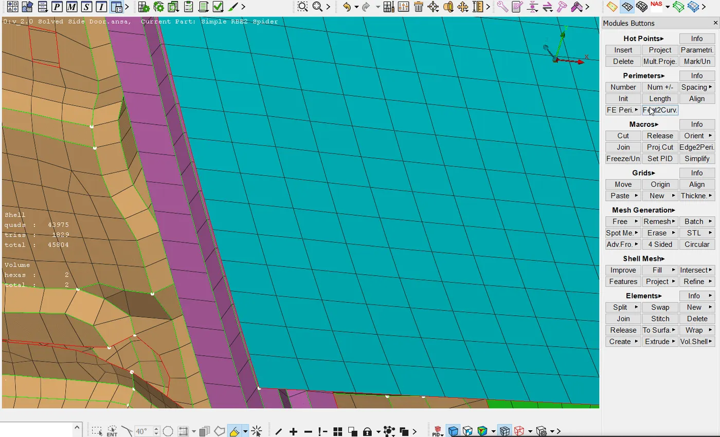
Fig 7.a: Creating a curve and converting it to Spot Line.
- Then, using the connection manager, we select the P1 and P2 as the glass and frame PIDs, provide the spacing value S, select the FE Rep Type as RBE3-CBUSH-RBE3, and provide the search distance as well as a PBUSH PID for the CBUSH.
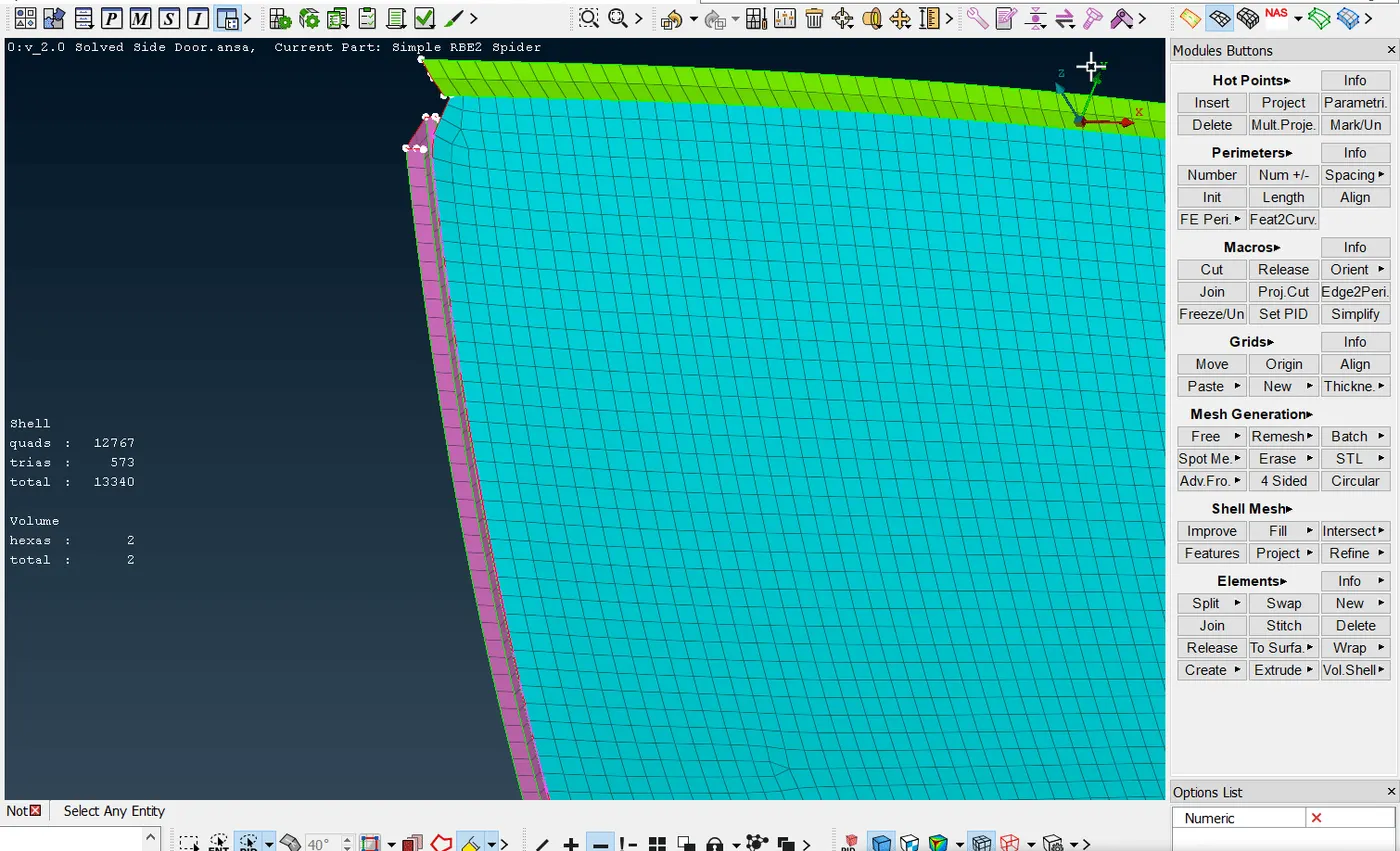
Fig 7.b: Realizing the CBUSH FE
- The thing to note here is that the glass is connected to two different frames by two separate CBUSH connections. Here we create two curves slightly translated from the glass FE edge so as to identify the spot lines better while selecting in the connection manager.
8. Now, we can create spot weld connections. To do this we have to first create a 3D Point where we want the spot weld connection and convert it into a Spot Weld using the Assembly> Convert function.
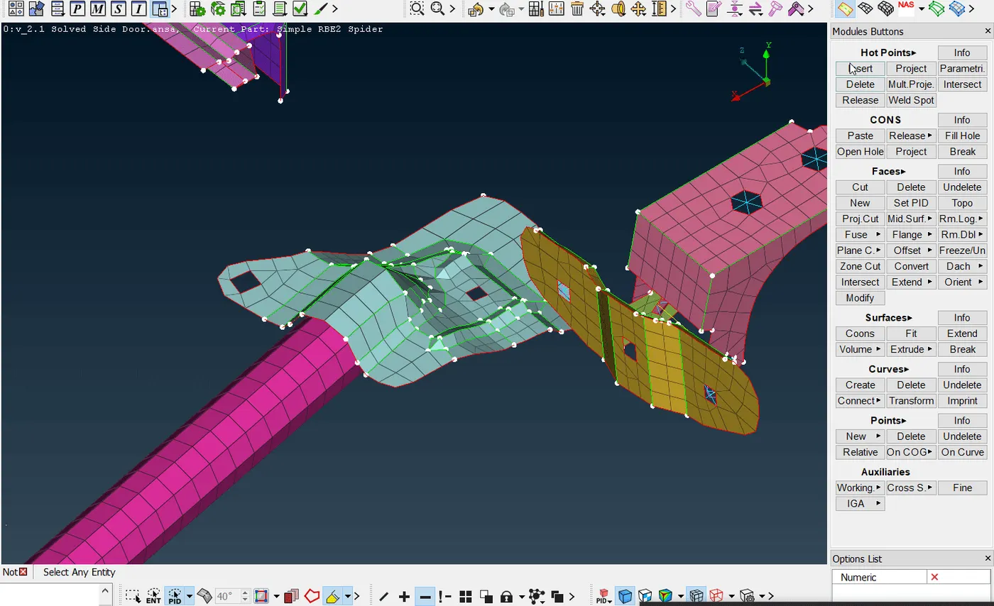
Fig 8.a: Creating a 3D point for the spot weld and converting it into a spotweld
- Then we use the Connections Manager to provide the P1 and P2, specify the FE Rep type as RBE3-HEXA-RBE3, and provide a search distance as well as a PSOLID PID for the spot weld.
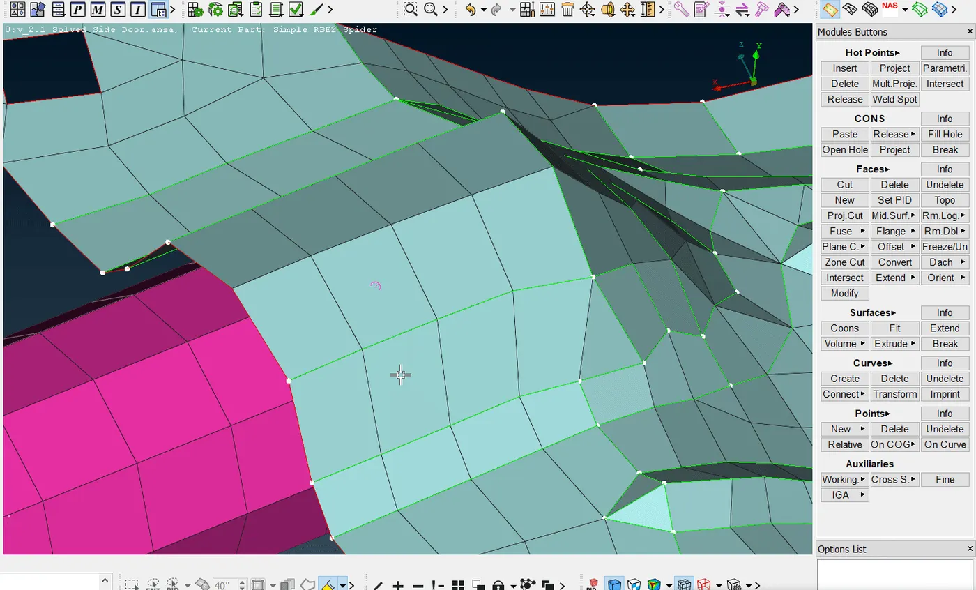
Fig 8.b: Realizing the Spot Weld FE
9. We then make appropriate connections at required locations for each component and realize their FEs.
Fig 9: Fully Connected Car door Model
- Conclusions:
The provided FE model of the Rear Car Door Assembly was firstly assigned unique PIDs to each component in order to distinguish and easily deploy connections between them. Then the connections were made by assigning appropriate parameters. These connections included bolt connections, spot welds, seam welds, CBUSH type of connection, etc. Simple as well as time-efficient techniques for making these connections were studied and the significance of constraining appropriate degrees of freedom for each type of connection was noted.
- Learning Outcomes:
1. The meaning and significance of connections were understood in reference to FE models in ANSA.
2. The different types of connections were learned like bolt connection, spot weld, seam weld, and CBUSH connections.
3. Different techniques were learned to create these connections both simple and time-consuming as well as sophisticated yet time-saving techniques.
#ENDNOTE#
Kindly note that the lower hinge bracket is not connected to the door assembly due to the faulty FE model that was provided for the challenge.