Week- 5 - Solid meshing
- Aim: For the given Rearview mirror component, check for the geometrical errors and mesh the Surfaces with the given 2D element Quality criteria given below.
|
S.No |
Quality Criteria |
Value |
|
1 |
Target/Average length |
1 |
|
2 |
Minimum Length |
0.5 |
|
3 |
Maximum Length |
2 |
Use tetra elements to mesh the Volumes defined in the model and check for the below quality after Volume meshing.
|
S.No |
Quality Criteria |
Value |
|
1 |
Tet collapse |
0.2 |
- Methodology:
1. Importing the CAD file into the ANSA environment.
2. Checking the CAD file for any Geometric Errors and performing the Geometric Cleanup of the same.
3. Meshing each component part in separate locked views as per given shell-meshing parameters and required Quality Criteria.
4. Defining closed volumes and properties for each component part and deploying an appropriate Solid/ Volume mesh algorithm to get a ‘Tetra-mesh’ representing the volume of the CAD.
5. Checking for any OFF elements with the given Quality criteria and appropriately rectifying the same.
6. Releasing the FE model from the parent CAD file and the volume of the same.
- Detailed Procedure:
1. Importing/opening the ANSA file of the Bottle Cap CAD model into the ANSA environment.
Fig 1: Importing the Original CAD file of the Rearview Mirror Assembly in the ANSA environment.
- As seen in Fig 1, the imported model does not have any connected surfaces and thus requires us to use Faces> Topo to get the surfaces to connect and the single cons will become double cons.
Fig 2: Fixing the single cons of the imported CAD model to get connected surfaces.
- As seen in Fig 2, after using Topo, the model is not oriented correctly so now we orient the outer surfaces of each component part. This can be done using the Orient> Visible and Orient> Select functions in the Faces Tab.
Fig 3: Oriented CAD model
- As seen in Fig 3, there are triple cons generated after using Topo. Thus, we can now check for any Geometric Errors and clean up the same as required.
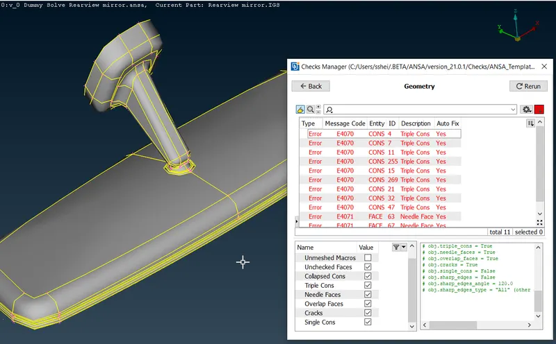
Fig 4: Errors noted in Geometric Check of the CAD model
- From Fig 4, it is observed that there are Triple Cons and Needle faces in the model. These can be fixed by selecting all and then right-clicking and selecting Fix.
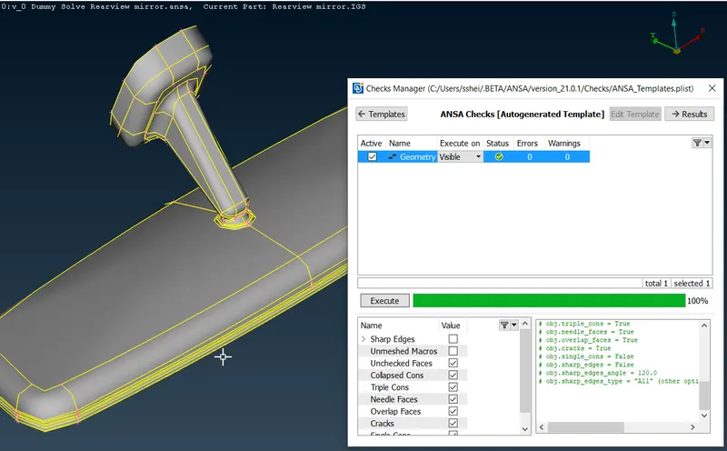
Fig 5: After fixing the Geometric Errors of the CAD model
- Now, we can separate the different components into different locked views for better access later on.
Fig 6: Separating the different components of the CAD model into different locked views.
- The given CAD model has four component parts, namely the Mirror, Body, Bush, and Mount.
- We can now smoothen the Perimeters and Macros for better visualization of the CAD and check for any surface irregularities, i.e. raised portions or kinks, etc.
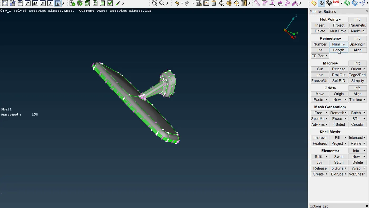
Fig 7: Smoothening of the CAD model edges and surfaces.
- It is noted as seen in Fig 7 that there are no issues with the geometry and further operations can be done.
2. We can now start meshing each component part as per the given Meshing Parameters and Quality Criteria.
- By Meshing, it is meant that the surfaces that define the boundary of the volume of each component part, are to be shell-meshed, and the volume mesh can then be generated as explained in this report further.
- Since we have already separated the component parts of the given CAD model in different locked views, it is easier for us to work on one component at a time i.e., defeature and mesh the components one by one.
- First of all, we need to define the Mesh Parameters and Quality Criteria as per the given data.
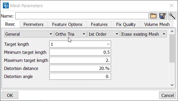
Fig 8.a: Setting Shell Mesh Parameters
- As seen in Fig 8.a, the element type has been selected as Ortho Tria. This is done because we will first shell mesh the curved surfaces of the Component using the Ortho Tria elements which give better surface coincidence with the mesh as compared to regular Tria elements.
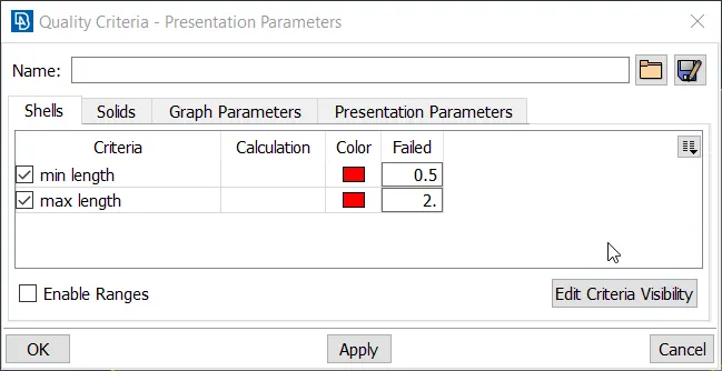
Fig 8.b: Setting the Quality Criteria for the Shell Mesh
- Now, we begin defeaturing and shell-meshing the components one by one starting with the component part Mirror.
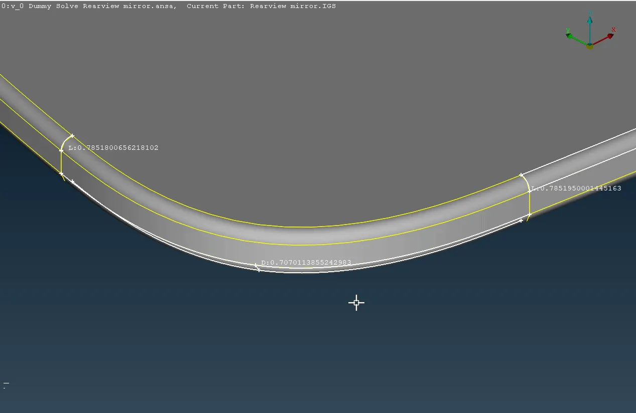
Fig 9.a: Inspecting features in Mirror that need defeaturing
- As seen in Fig 9.a, the only features that do not satisfy the required parameters and the quality criteria are the two fillets that exist on the whole periphery of the Mirror. This can be let as is to preserve the quality of the other surfaces.
Fig 9.b: Shell-meshing the Mirror Component part
- It is seen from Fig 9.b that the fillets are captured with a single row of Ortho-Tria elements as two rows of elements fail for Minimum Length Quality.
- It is also noted that the curved surfaces of the component meshed with Ortho Tria elements show good coincidence with the parent CAD surfaces. This was the purpose of using the Ortho Trias on curved surfaces.
- The mostly flat surfaces are meshed using regular Tria elements as they do give flat mesh with no kinks or raised peaks as well as take less time for computation as compared to Ortho-Tria elements.
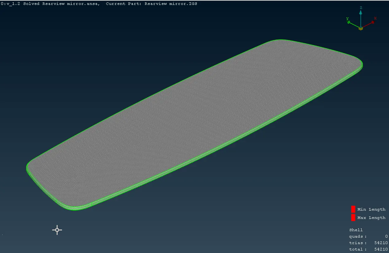
Fig 9.c: Completely shell-meshed Mirror Component
- Now, we can work on the other component parts in the same way, i.e., by first defeaturing necessary features in the components and then shell-meshing the components' curved surfaces with Ortho-Tria elements and finally shell-meshing the flat surfaces with Tria elements.
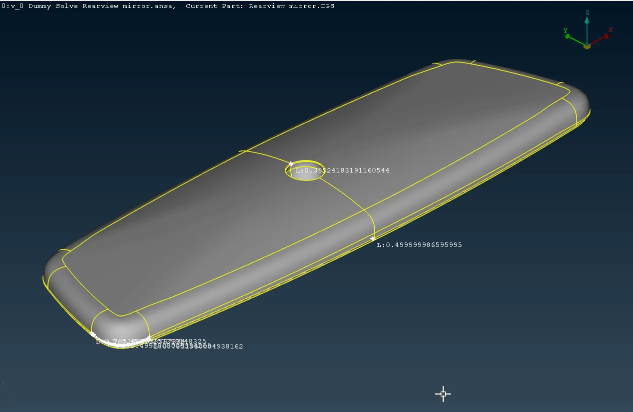
Fig 10.a: Mirror Body CAD part before defeaturing
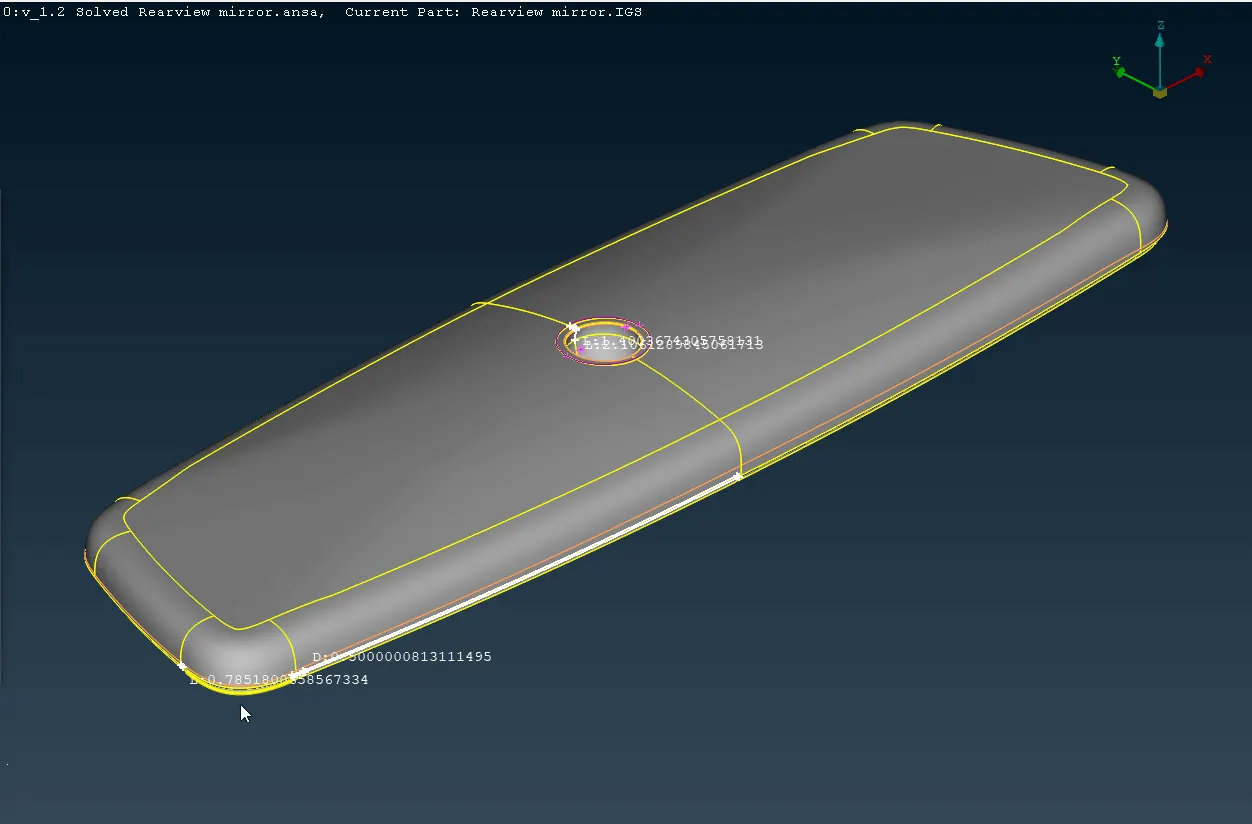
Fig 10.b: Mirror Body CAD part after defeaturing
- As seen in Fig 10.b, the bottom fillet was initialized to be captured with a single row of elements. The extra cons near this fillet were also suppressed as they failed for minimum length criteria at the corners of the Body.
- The fillet on the top socket was defeatured by first creating a curve on the middle of the fillet edges and then projecting it on the fillet surface, another curve/circle was created on the top surface and projected onto the same as double cons. Finally, the fillet edges were suppressed.
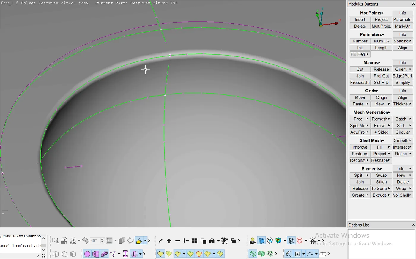
Fig 10.c: Shell-meshing the top socket in the Body
- As seen in Fig 10.c, the top socket and the fillet are shell-meshed using the Ortho-Tria elements. It is noted that the first row of the elements that occur on the midline of the fillet is slightly tilted as compared to their adjacent rows of elements. This is why there are two curves made near the fillets earlier on to capture both the fillet as well as the parent surfaces as correctly as possible.
- The inner curved surfaces of the socket are also meshed with Ortho Tria elements. All other curved surfaces are also meshed using Ortho Tria elements while flat surfaces are meshed using Tria elements for reasons explained earlier.
Fig 10.d: Completely shell-meshed Body component
- Now, we work on defeaturing and meshing the Bush component.
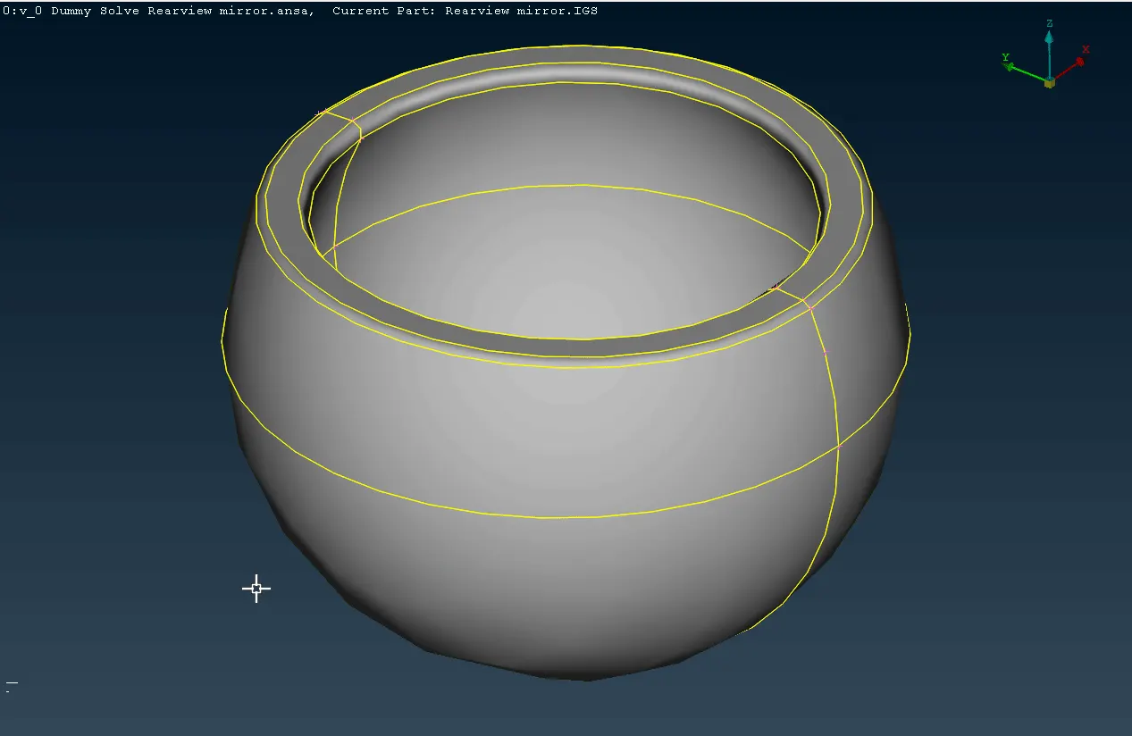
Fig 11.a: Bush component before defeaturing
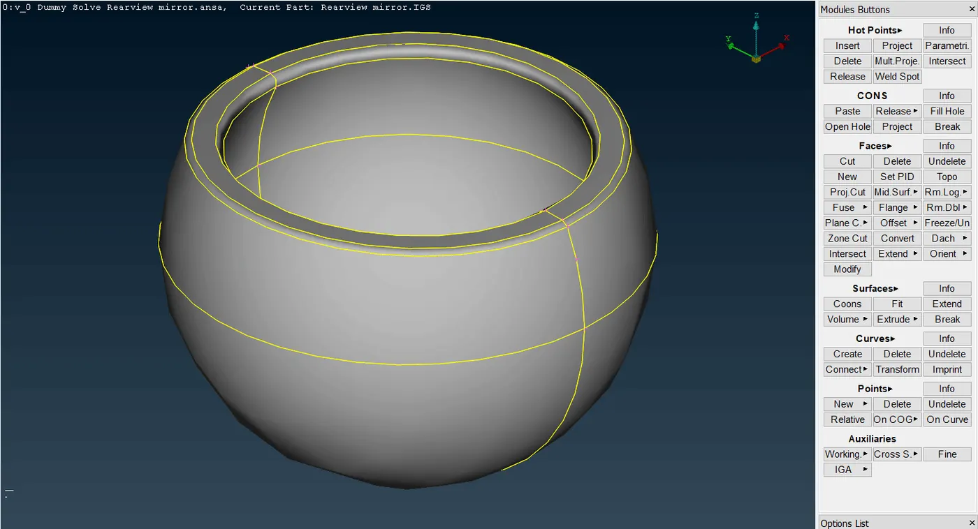
Fig 11.b: Defeaturing Bush component
- The top fillets in the Bush are too small to be captured in the mesh of required quality, hence it is better to completely remove the fillets using the Faces> Dach function as seen in Fig 11.b. The Dach function gives straight edges in place of the fillets.
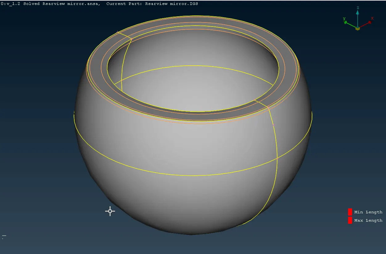
Fig 11.c: Completely shell meshed Bush component
- Now, we work on the Mount component part.
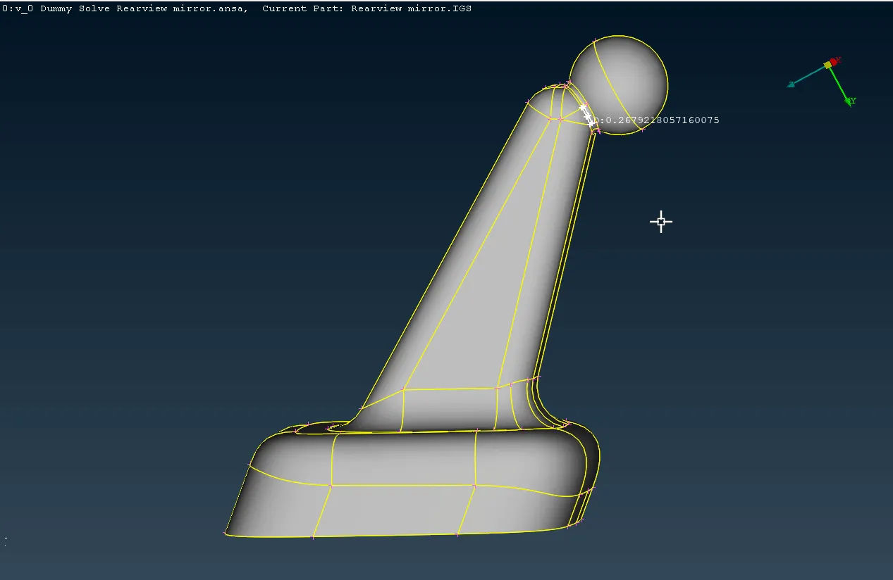
Fig 12.a: Mount component before defeaturing
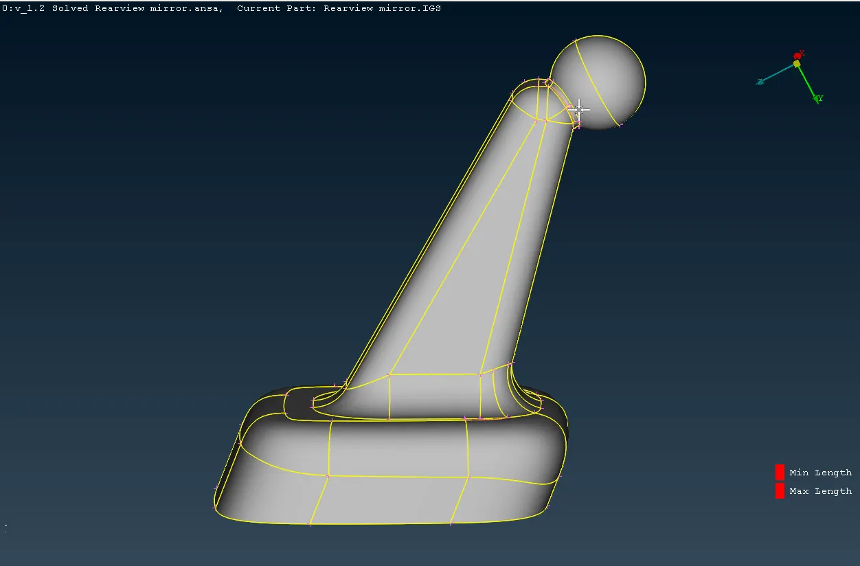
Fig 12.b: Mount component after defeaturing
- In Fig 12.a, we see that there are not many features in the Mount that require defeaturing. We just need to suppress the extra double cons and the bottom cons which form a sharp point. Also, in Fig 12.b, it is clear that a cut is needed to close the flat surface on either side where the original cons formed a sharp junction.
Fig 12.c: Completely shell-meshed Mount component
- It is again noted that the curved surfaces are better captured when using Ortho Tria elements and Tria elements require less computation time thus only used on flat surfaces. Some areas may give better quality mesh with Tria elements independent of it being flat or curved, user has to decide which to use when.
Fig 13: Completely Meshed Rearview Mirror CAD assembly
3. Defining closed volumes for each component part and deploying an appropriate Solid/ Volume mesh algorithm to get a Tetra-mesh representing the volume of the CAD.
- Now, as all the components have been shell-meshed, we can now generate the Volume-Mesh or Tetra-Mesh for each component one by one.
- For this, we need to first define each component part as a separate closed volume and then use a volume-mesh generating algorithm.
Fig 14: Defining closed volume, PID for the Mirror Component and volume meshing the same
- In Fig 14, the process of defining a closed volume as well as a solid property(PSOLID) for the Mirror CAD component and then Volume-meshing the component is shown.
- The volume is defined using Define> Select> Manual under the Volumes tab in the Volume Mesh Module. The shell-meshed CAD geometry of the Mirror component is then selected and confirmed with a middle mouse click. An unmeshed volume is now defined as seen in Fig 14.
- The solid property for the Mirror component is created in the Properties list by using New> PSOLID> PSOLID, then giving desired PID, MID, Color, and Name with finally selecting OK.
- This property can then be applied to the volume generated by using Apply and selecting the Mirror component volume in the graphical window and confirming with the Middle mouse click.
- This unmeshed volume can be seen in the List volume library under the Volumes tab in the Volume Mesh Module. This unmeshed volume can directly be meshed from this List by right-clicking and selecting Remesh and the appropriate algorithm after that.
- Alternatively, after defining the volume we can directly use an algorithm from the Unstructured Mesh Tab like Tetra Rapid or Tetra FEM.
- We can now define the Solid Mesh Quality Criteria as per given data i.e., the required Tet Collapse quality as 0.2 in Quality Criteria> Solids.
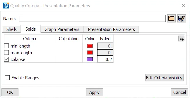
Fig 15: Setting up Volume mesh Quality Criteria
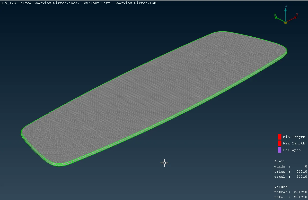
Fig 16: Checking the volume mesh for any OFF elements as per given Tet Collapse quality
- It is noted in Fig 16 that there are no OFF elements in the volume mesh for the Mirror component. If there were any, we can rectify the same by moving one or more of the nodes by using Improve> Move till quality is satisfied. The only thing to be aware of is that this movement does not distort the outside surface of the model. In other words, the nodes that are not on the outside surface can only be moved and that too in the direction away from the surface.
- We can now generate the volume-mesh for the remaining components in the same way, i.e., by first defining closed volumes for each component and then using a volume-meshing algorithm.
Fig 17: Completely Volume-meshed or Tetra-meshed Rearview Mirror Assembly
- Fig 17 shows a completely volume-meshed assembly of the given CAD model. It can also be seen that there are no OFF elements at all in either the shell mesh or the volume mesh of the CAD.
- It is also noted that the CAD surfaces or the shell mesh are attached to the volume mesh as evident during the timestamps 1:42 to 1:58 in Fig 17 by selecting Neighbours> All, the shell mesh appears. In other words, the volume mesh is attached to the volume and thus is not identified as a FE model.
- For the actual solving of this model, it is necessary to separate the volume and the volume mesh, i.e. make ANSA identify the volume mesh as a FE model.
- This can be done by first switching ON just the Volume and Wire views and switching OFF the FE-Mode and Geometry views. Bounds can also be switched ON for better visibility. After this, we can select the volumes on the graphical window and use Volumes> Release in the Volume Mesh module to release the same.
Fig 18: Releasing the generated FE model from the CAD and volume of the Rearview Mirror Assembly
- Conclusion:
A Volume-mesh or more accurately a Tetra-mesh was generated for the given Rearview Mirror CAD assembly with the given Mesh Parameters and the Quality Criteria. The procedure for the same is explained in detail in this report. Required defeaturing was done before meshing and Quality parameters were checked after the meshing was completed. Finally, the generated volume mesh or the FE model thus generated was then released from the parent CAD model and its volume.
- Learning Outcomes:
- The theoretical knowledge on 3D/ Volume meshing and subsequently Tetra and Hexa meshing was firstly understood before this project was started.
- The differences between Structured and Unstructured Mesh were understood along with its applications and significance.
- The significance of the surface quality of a Volume-meshed model and its coincidence with the original CAD model surfaces was noted.
- The differences in the Tetra Meshing algorithms namely Tetra Rapid and Tetra FEM were understood.
- The concept of Growth Rate in a volume mesh algorithm was understood.
- The meaning and significance of the quality criterion Tet Collapse were understood along with its rectification if any tetra element fails for the same.
- I also learned how and why to release the generated Volume Mesh, Shell Mesh, or simply any FE model from its parent CAD model.