Week 3 - 2D meshing for sheet metal
- Aim : For the given Hood model, take the mid surface for all the components after checking the geometrical errors and mesh the mid surface with the given element Quality criteria. (Refer the table below for the Quality criteria)
|
S.No |
Quality Criteria |
Value |
|
1 |
Target/Average length |
5 |
|
2 |
Minimum Length |
2 |
|
3 |
Maximum Length |
7 |
|
4 |
Aspect |
3 |
|
5 |
Warpage |
15 |
|
6 |
Skewness |
45 |
|
7 |
Jacobian |
0.7 |
|
8 |
Minimum Quad Angle |
45 |
|
9 |
Maximum Quad Angle |
135 |
|
10 |
Minimum Tria Angle |
30 |
|
11 |
Maximum Tria Angle |
120 |
|
12 |
Tria Percentage |
15 |
- Methodology:
- Importing the CAD model into ANSA environment.
- Checking individual parts of the CAD file(assembly) for geometric errors and performing geometric cleanup of the same.
- Extraction of ‘mid-surface’ from the parent sheet metal components and applying respective properties.
- Meshing the mid-surfaces of the components as per given required Quality Criteria.
- Assigning the properties (like thickness and material) to each component mesh.
- Detailed Procedure:
1. Import CAD Geometry into ANSA.
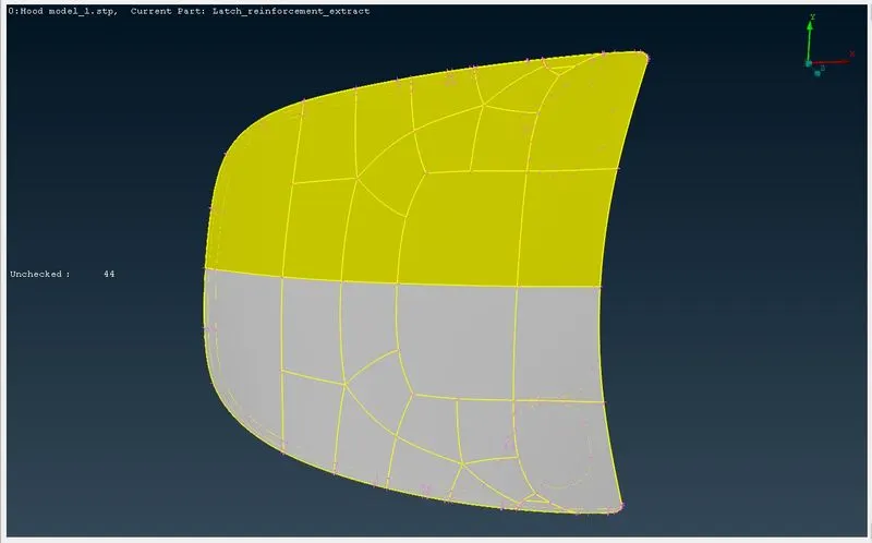
Fig 1.a: Top View of imported CAD model
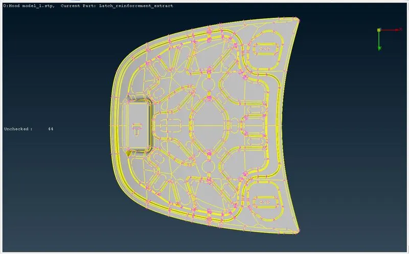
Fig1.b: Bottom View of imported CAD model
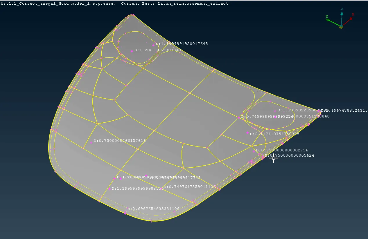
Fig 2: Detailed view of imported CAD geometry
- Noted that all cons and hot-points are visible in the model meaning Graphics Card is compatible for the assignment and no additional ANSA command arguments are required. Optionally, we can use ‘-performance_mode 3’ as Additional ANSA command argument to run ANSA in enhanced mode if we face any graphics incompatibility.
2. Separating the component-parts of the hood assembly namely, outer panel, inner support/strengthening panel, latch reinforcement and hinge reinforcements into different lock views for better access during the whole process.
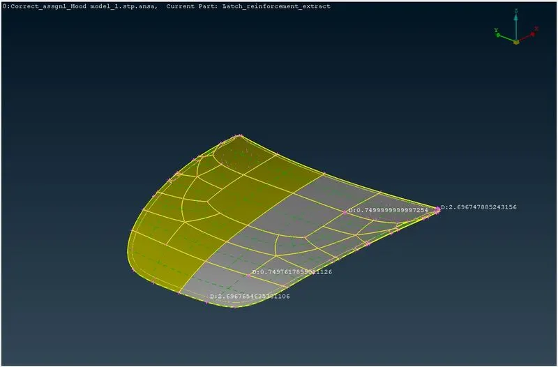
Fig 3: Outer panel for the hood assembly
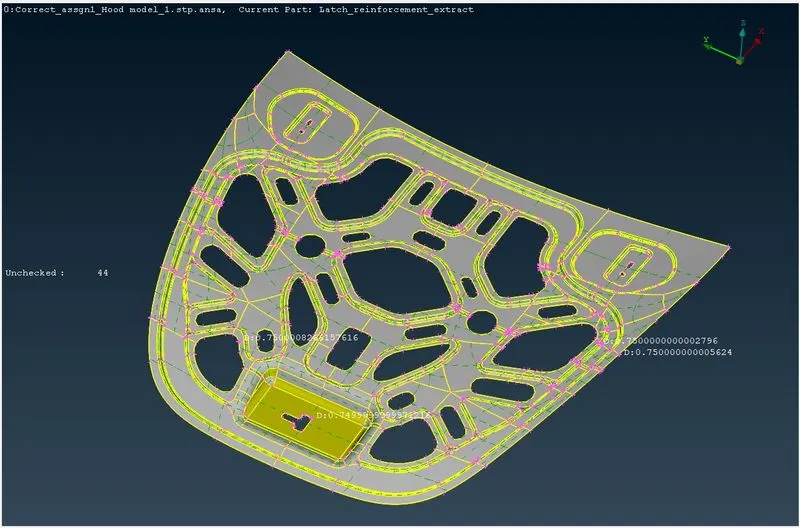
Fig 4:Inner Strengthening Panel for the Hood assembly
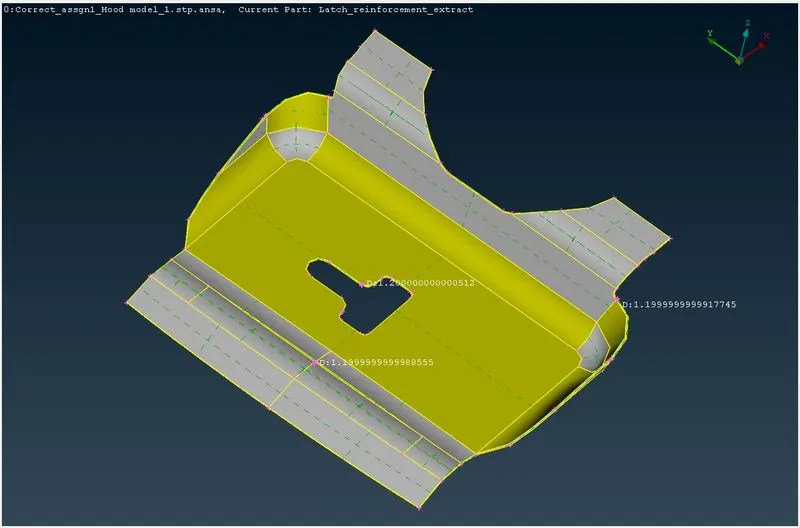
Fig 5: Latch Reinforcement
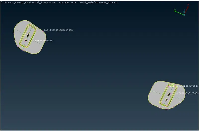
Fig 6: Hinge Rinforcements
- To identify the reinforcements, I had to check the thickness for different sections. The reinforcements are 1.2 mm thick while the inner and outer panel are 0.75 mm thick.
3. Perform topology and geometric cleanup on each of the four components. Orient the surfaces correctly, check for unstitched surfaces, cracks, triple cons, needle faces, etc.
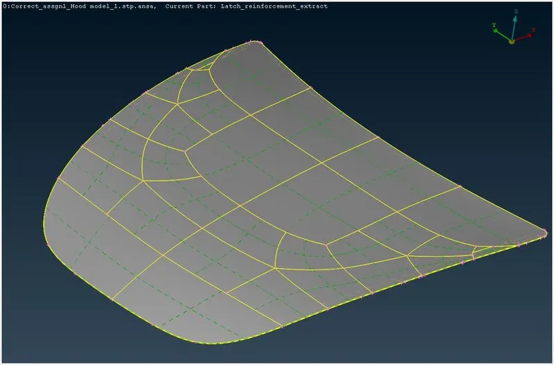
Fig 7.a: Oriented the surfaces of the Outer panel
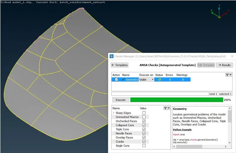
Fig 7.b: Performed Geometric Check on Outer Panel
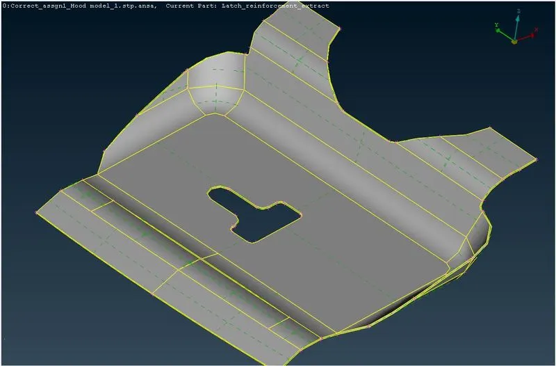
Fig 8.a: Oriented the surfaces of the Latch Reinforcement
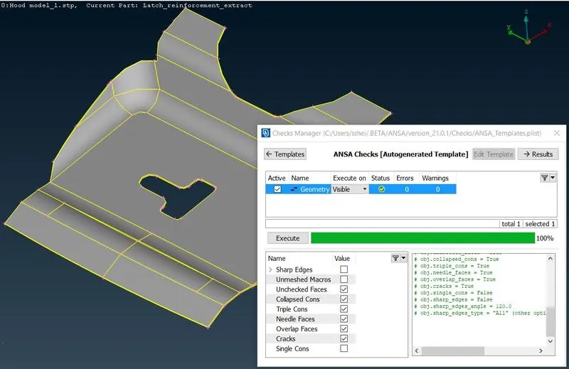
Fig 8.b: Performed Geometric Check on Latch Reinforcement
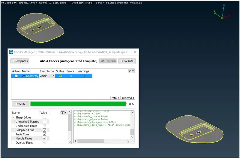
Fig 9. Performed geometric check on Hinge Reinforcements and oriented the same
- Found no errors in geometric check of Outer panel, hinge and latch reinforcements.
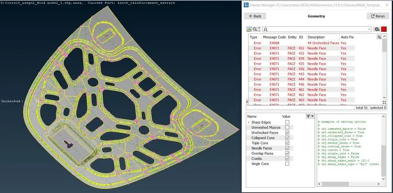
Fig 10: Performed geometric check on the Inner panel
-
Found 51 errors in geometric check of Inner Panel.
-
Note that most of the errors found here are ‘Needle Faces’ or ‘Unchecked Faces’ errors.
4. Rectifying the errors in Inner Panel after performing geometric check by right-clicking on the errors and then clicking on fix, i.e., using Auto-Fix function.
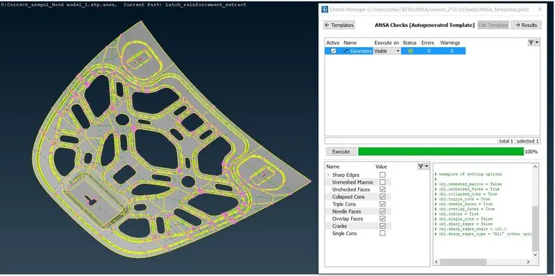
Fig 11: Geometric errors removed from the Panel and oriented the surfaces.
5. After the topology and the geometric cleanup is done, we can extract the mid surfaces for the component CAD models.
- To do this, first we have to note the thickness of each sheet metal component first. The thickness for the Outer panel, Inner panel, Hinge reinforcement and Latch reinforcements are 0.75 mm, 0.75 mm, 1.2 mm and 1.2 mm respectively.
- Another point to note is that the Outer panel is bent on its edges, called hemming.
6. Since we have found all the component thicknesses, it’s easier to create the properties for each of these components right now.
- To create a new property, go to Properties Tab then select New>PSHELL>PSHELL. Rename the property and put the thickness values for each component.
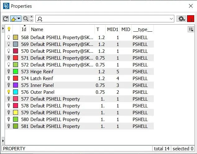
Fig 12: Creating PID for each component of the Hood Model
7. Extracting the mid-surface of each component using the Faces > Offset feature and selecting faces on the components. We give offset distance as half the thickness of the component inwards.
- The Offset feature is used to manually extract mid-surface of each component and hence is very time consuming and recommended only for complex surfaces. Also, the cons are not connected between two adjacent parts, i.e., each adjacent surface will have single cons on edges and will need Topo to make them one double con.
- Alternatively, we can extract the mid-surface by using the Faces > Mid-Surface > Skin option to save time. Using this feature and selecting various surafces at once gives mids for each, with proper cons.
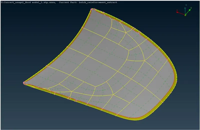
Fig 13: Mid-surface of the Outer Panel
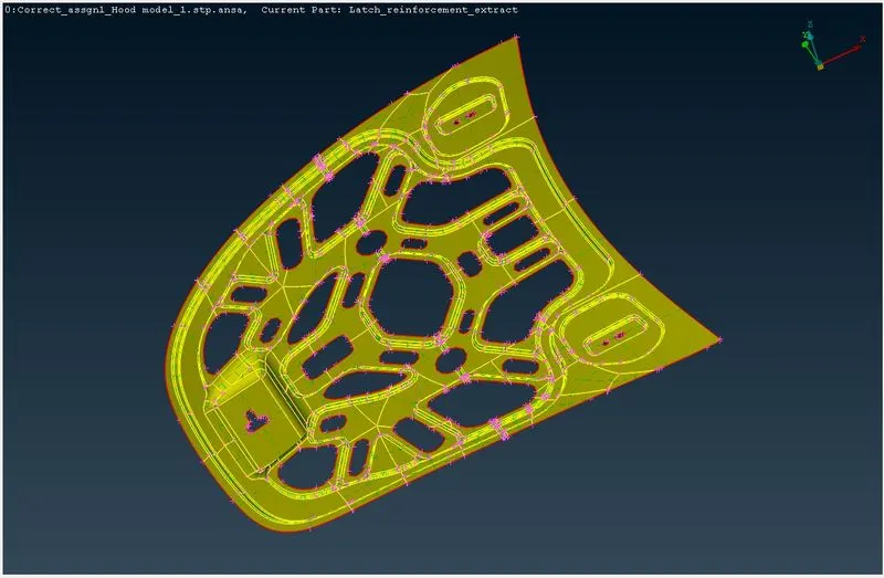
Fig 14: Mid-surface of Inner Panel
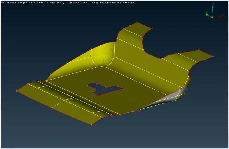
Fig 15: Mid-surface of Latch Reinforcement
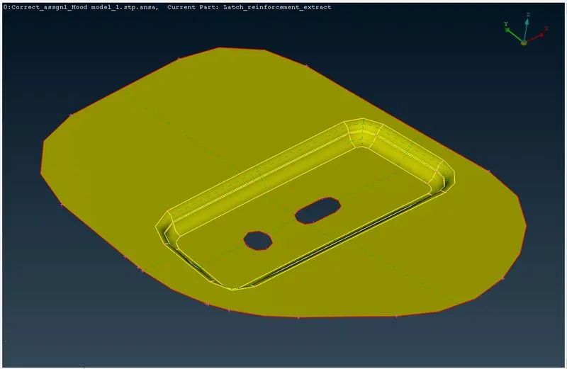
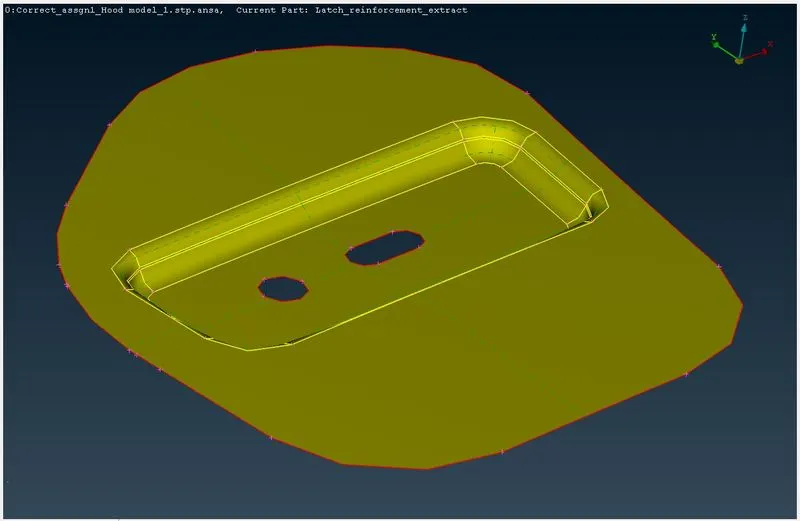
Fig 16.a & Fig 16.b: Mid-surface of the Hinge Reinforcements
- After extracting mid-surfaces, perform geometric checks and fix errors if any.
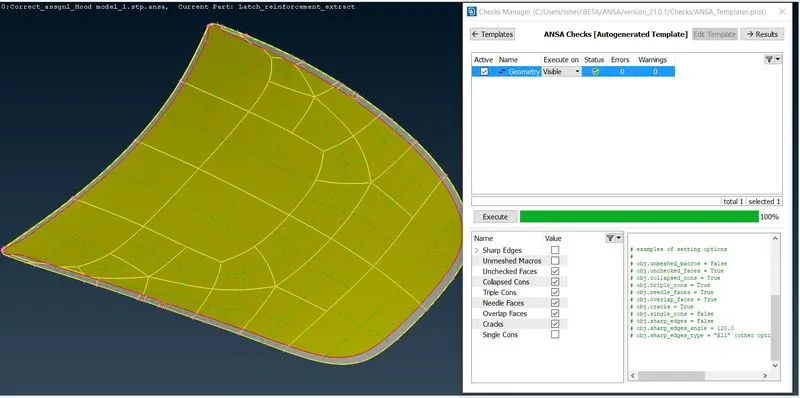
Fig 17: Oriented and performed geometric check on the Outer panel mid-surface
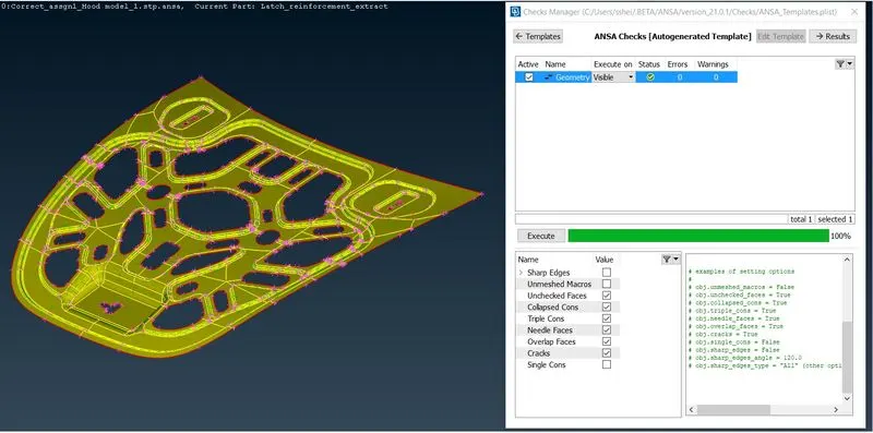
Fig 18: Oriented and performed geometric check on the Inner panel mid-surface
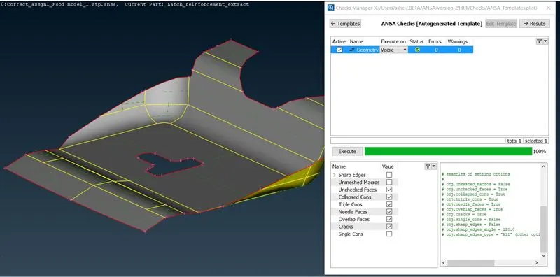
Fig 19: Oriented and performed geometric check on the Latch Reinforcement mid-surface
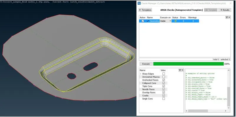
Fig 20: Oriented and performed geometric check on the Hinge Reinforcements mid-surfaces
- Found no geometric errors in the mid-surfaces of any component.
- Apply the properties of the components to their respective mid-surfaces using Properties > Apply.
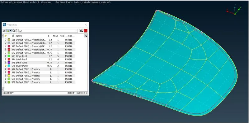
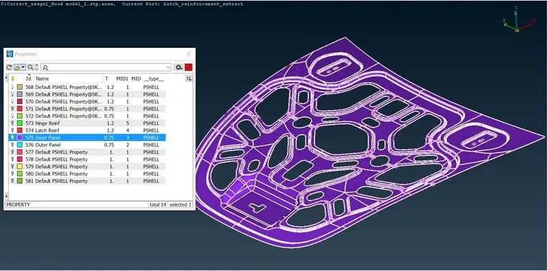
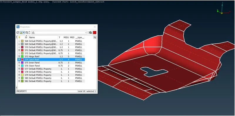
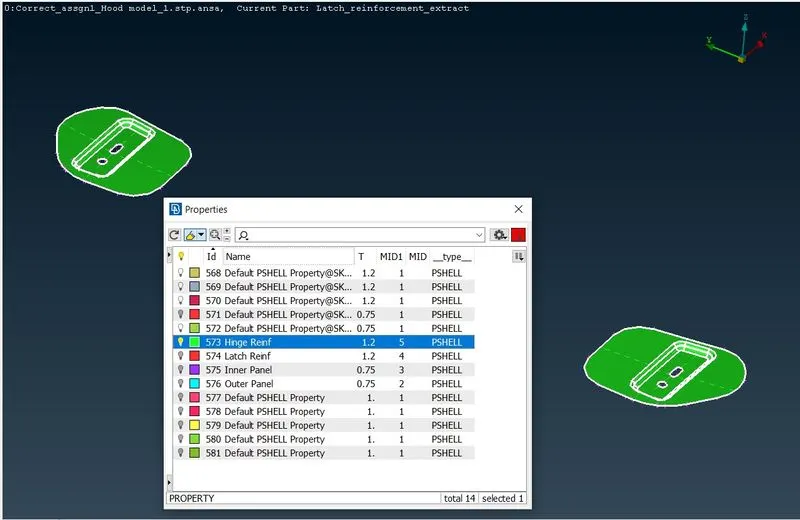
Fig 21 to 24: Applied respective PID to each components’ mid-surface
8. Now, we set up the mesh parameters as well as quality criteria for the created mesh as per given data.
- The mesh parameters are set up at Utilities> Mesh Parameters as per given data, i.e., Target/Average length, Minimum Length, Maximum Length to be 5 mm, 2mm and 7mm respectively.
- The quality criteria are set up at Utilities> Quality Criteria as per given data.
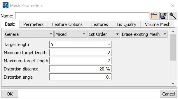
Fig 25.a: Setting Mesh Parameters
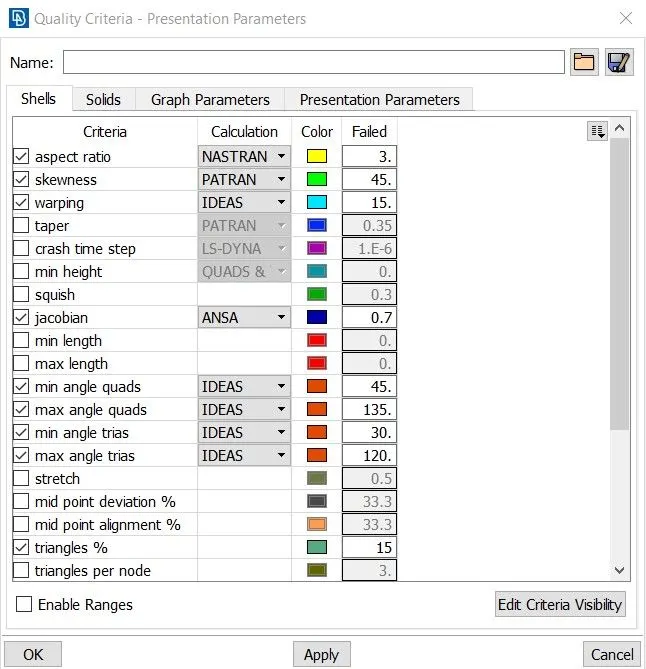
Fig 25.b: Setting Quality Criteria
9. Meshing the mid-surfaces of each component.
- Starting with the component having the most features or complex geometries. Thus, we mesh the Inner Panel first, then the Outer Panel and finally the reinforcements.
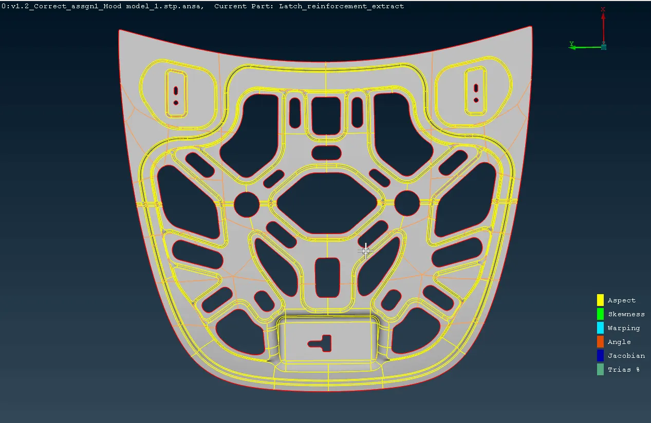
Fig 26: Suppressing the original double cons to make the mesh flow better.
- Note that this panel has some surfaces that do not satisfy the mesh parameters and quality criteria, hence defeaturing is required which is done by suppressing the double cons, or slightly modifying the fillets, etc. The double cons in Fig 26 can be seen in two colors of which the orange ones are suppressed using the Macros> Join in the Mesh module.
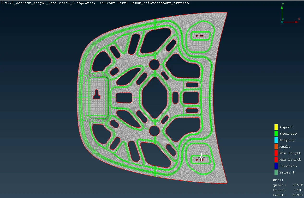
Fig 27: Meshed Inner Panel mid-surface
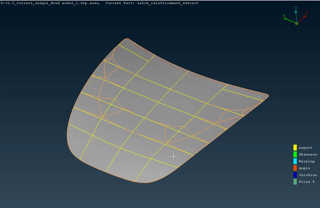
Fig 28: Suppressing the original cons in the Outer Panel
- New Macro Cuts are made on the Outer panel in order to get better mesh flow.
- The Outer panel has hemming which needs defeaturing in order to follow the mesh parameters and satisfy the quality criteria.
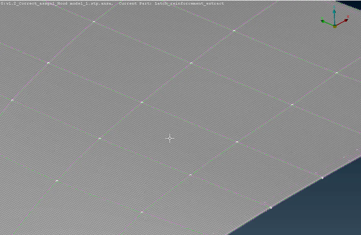
Fig 29: Meshed Outer panel mid-surface
- Note that the mesh at the hemming region is possible only after defeaturing as seen in Fig 29.
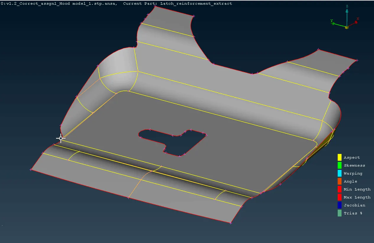
Fig 30: Topology Cleanup of the Latch Reinforcement mid-surface
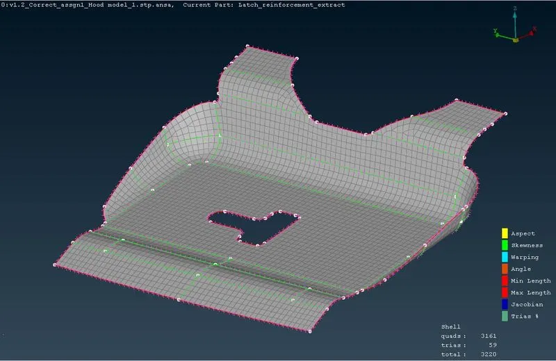
Fig 31: Meshed Latch Reinforcement mid-surface
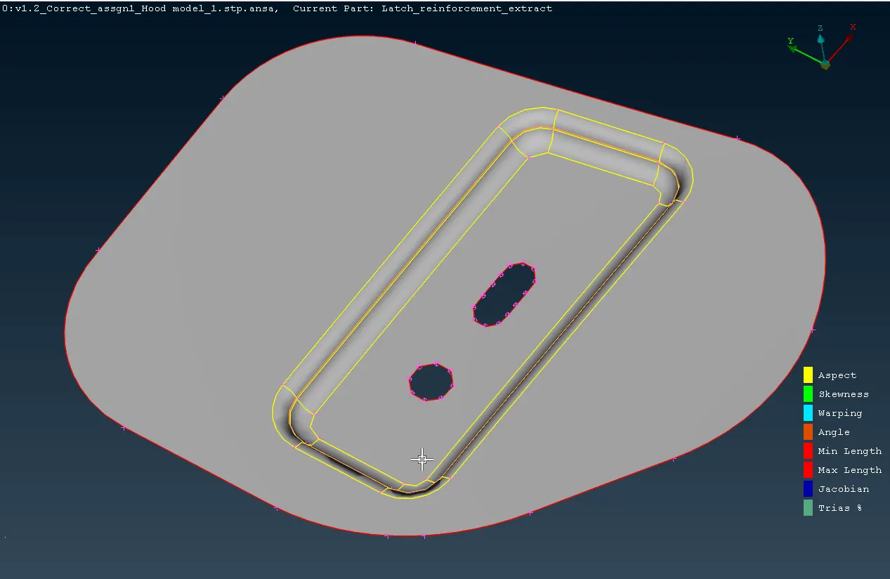
Fig 32: Defeaturing the Hinge Reinforcement mid-surface
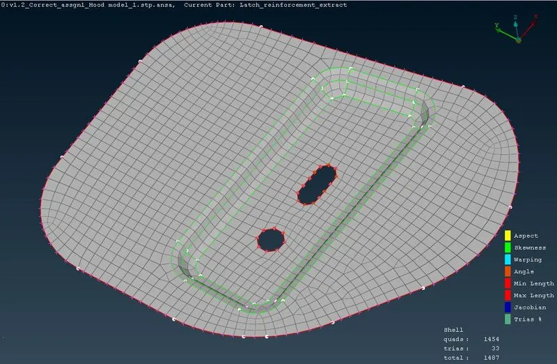
Fig 33: Meshed Hinge Reinforcement mid-surface
- Note that the holes in this component need to have even number of nodes and the ends of the curved edges should be parallel to nearest boundary for better mesh flow.
10. Finally, the mesh representation as solid shells is done. To do this, we go to Utilities> Quality Criteria> Presentation Parameters and check on the Draw shell as solid option then Apply and OK.
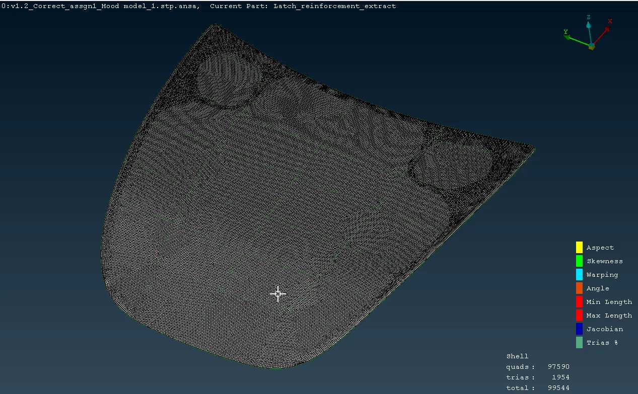
Fig 34: Thickness applied to the meshed model
- Conclusion:
The given CAD model of Hood assembly was meshed as per the given Mesh Parameters and the Quality Criteria. Different techniques and concepts were studied for 2D meshing of sheet metal components.
- Learning Outcomes:
- Learnt how to perform Topology and Geometric Clean-up within the ANSA GUI.
- Learnt about the types of geometric errors in imported CAD models and their resolution.
- Learnt about mid-surfacing and its application in 2D meshing.
- Learnt about the necessity of defeaturing prior to starting the meshing.
- Learnt about different quality criteria like Aspect ratio, Warpage, Skewness, etc.
- Learnt about the mesh flow and how to minimize trias in the final mesh as well as the need of dividing a big surface into small manageable areas for better mesh flow.
- Learnt about required mesh patterns for different applications like NVH analysis, Crash analysis, etc. and the role of quads and trias for these applications.