Week - 4 - 2D meshing for Plastic components
- Aim: For the given Plastic Bottle Cap model, check for the geometrical errors and take the mid surface by suitable mid surfacing techniques. PID and Thickness assignment has to be done for all the mid surfaces. Mesh the same with given element Quality criteria. (Refer the table Below for the Quality criteria)
|
S.No |
Quality Criteria |
Value |
|
1 |
Target/Average length |
1 |
|
2 |
Minimum Length |
0.5 |
|
3 |
Maximum Length |
3 |
|
4 |
Aspect |
3 |
|
5 |
Warpage |
15 |
|
6 |
Skewness |
45 |
|
7 |
Jacobian |
0.7 |
|
8 |
Minimum Quad Angle |
45 |
|
9 |
Maximum Quad Angle |
135 |
|
10 |
Minimum Tria Angle |
30 |
|
11 |
Maximum Tria Angle |
120 |
|
12 |
Tria Percentage |
15 |
- Methodology:
- Opening the ANSA file of the Bottle Cap CAD model into the ANSA environment.
- Checking the CAD file for any Geometric Errors and performing the Geometric Cleanup of the same.
- Extraction of ‘mid-surfaces’ from the parent component and creating respective PIDs.
- Meshing the mid-surfaces of the components as per given meshing parameters and required Quality Criteria.
- Assigning the properties (like thickness and material) to each component mesh.
- Detailed Procedure:
1. Opening the Bottle Cap CAD model into the ANSA environment.
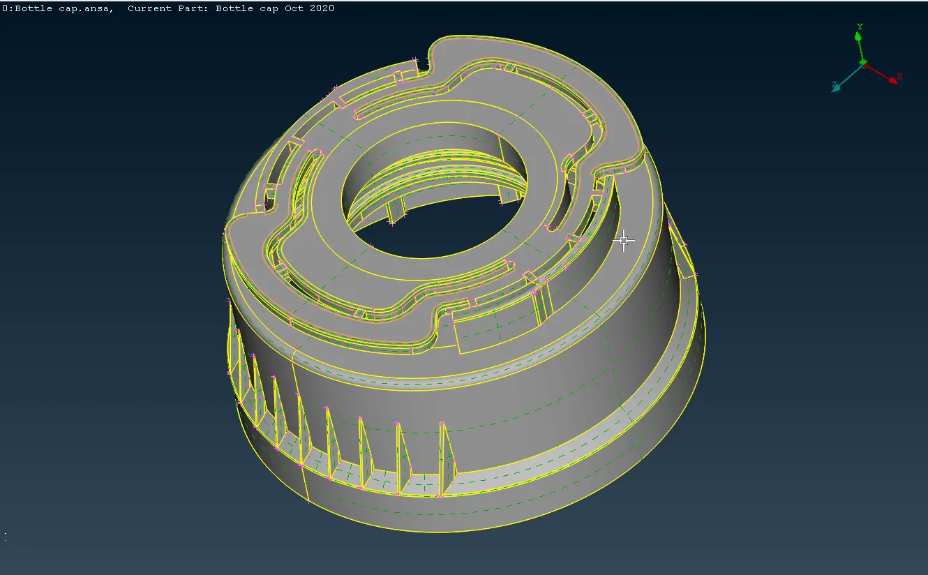
Fig 1: Detailed View of the Original CAD model of the Bottle Cap
- Noted that all cons and hot-points are visible in the model meaning Graphics Card is compatible for the assignment and no additional ANSA command arguments are required. Optionally, we can use ‘-performance_mode 3’ as Additional ANSA command argument to run ANSA in enhanced mode if we face any graphics incompatibility.
- Also noted that, since the Bottle Cap model seems complex, it can be simplified for further operations by seperating it into different locked views for different sections.
2. Perform geometric checks on the CAD model. Also, perform topology and geometric cleanup of the model. Orient the surfaces if necessary.
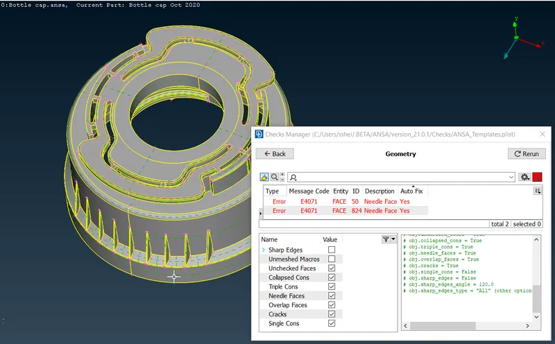
Fig 2: Performed Geometric Check on the CAD model
- Found 2 Needle Faces errors in geometric check of the CAD model.
- We can use the Auto-fix function to rectify these errors. Right-clicking on the errors and then Fix.
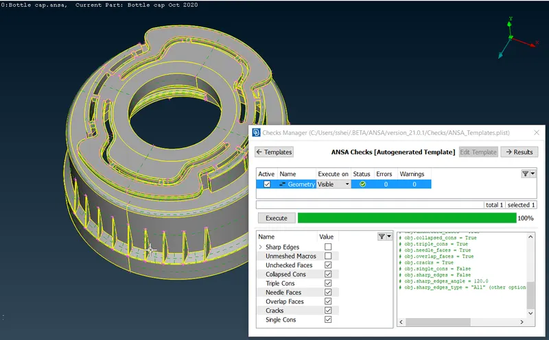
Fig 3: Geometric errors removed from the CAD model
3. After the topology and the geometric cleanup is done, we can extract the mid surface for the CAD model.
- We can use various techniques and features for mid surface extraction as the plastic component has varying thickness at different sections.
- We can also try the tool Faces> Mid.Surface> Casting from the TOPO module to get automatic mesh generation for the given plastic CAD model. If we get a perfect meshed FE model, our job will be done. It is seldom a case where the Auto-Mid actually gives a perfect FE model. However, it helps us see what areas are complicated and need attention and the rest can be simply generated.
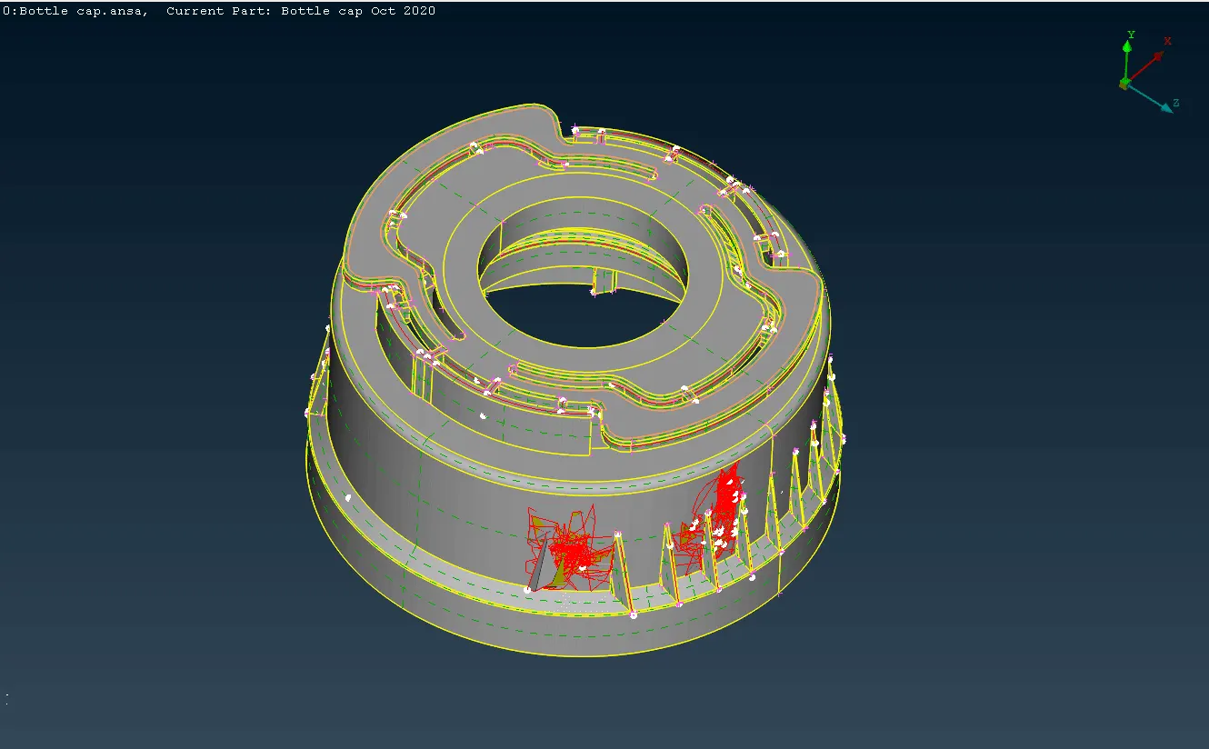
Fig 4: Auto-mid FE generated by ANSA for the CAD model
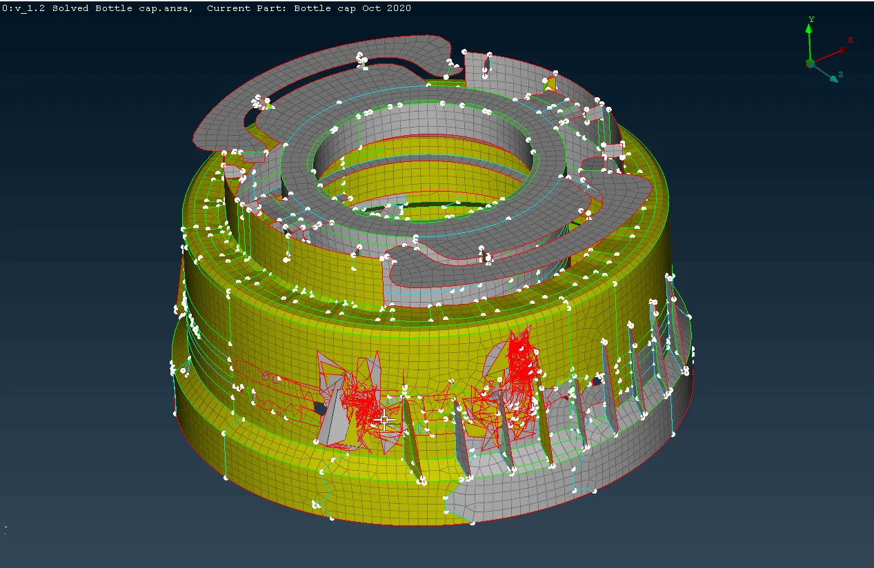
Fig 5: Improper Mid and mesh generation by Auto-mid
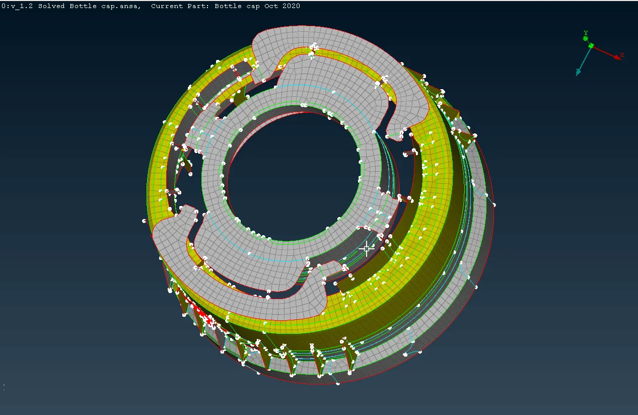
Fig 6: Disconnected elements and absent geometry in Auto-mid FE model
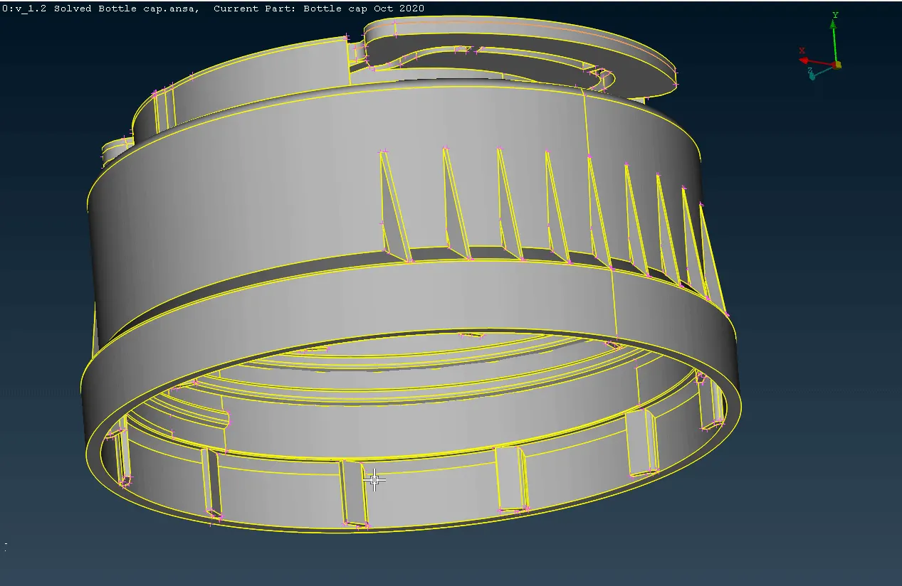
Fig 7: Improper Mid generated for teeth
- As can be seen in the Fig 4, 5, 6 and 7, the mid-surfaces and mesh generated by Auto-mid are far from ideal and need to be done manually. But, the thing to note here is the areas where ANSA has had trouble are the areas that need our attention the most, namely the ribs on the outside, the top where the vertical mid meets the horizontal mid, the inside teeth on the bottom section. Also, the inside teeth on the top are not at all captured in the mid and are rather captured as indentations in the horizontal surface as seen in Fig 5 and 6.
4. Now, we have to manually extract mid surfaces for the CAD model using functions like Offset and Middle from the Faces group. Starting with the flat walls and the top surface we can then work on the features on them.
- To take mid using Offset function, first measure the thickness of corresponding surfaces. Use half of this thickness as offset distance for the mid-surface. Since, this is a plastic cast part, the thickness at each section will be different and hence we will have to set unique PIDs for each mid corresponding a thickness change.
- The PIDs can be set later, right now we can just measure and store the measurements of each section.
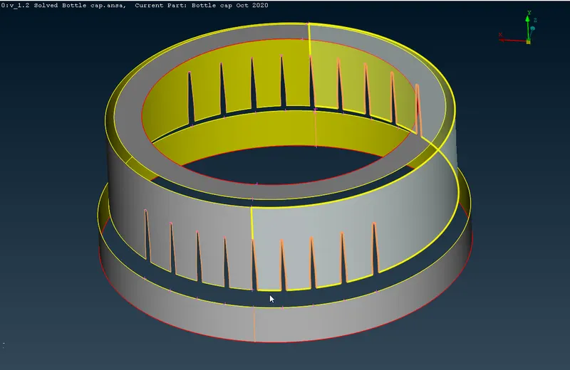
Fig 8: Taking mid of the substrates
- Now, here the substrate surface has openings where the ribs attach. These can be filled using the feature Faces> New and in that, Existing Surface, Planar, Fitted and Cons can be used as required. Faces> Cut can be used to suppress the double cons formed.
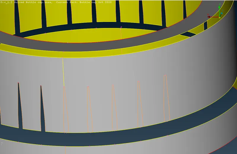
Fig 9. Filled gaps in the substrate surface
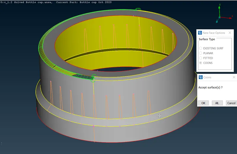
Fig 10: Extracting the fillet region mid surface
- In Fig 10, the mid-surface of the fillets can be taken using Middle or Offset but using Faces> New> Cons gives connected mid-surfaces already.
- Now, we can start to extract the mid surface for the outside ribs. To do this, we can use the Curves> Create function and trace the mid of the rib like shown in the Fig 11 below.
Fig 11: Extracting the mid-surface of outside ribs
- Using the Faces> Extend function we can extend the floating mid-surface of the rib to the substrate.
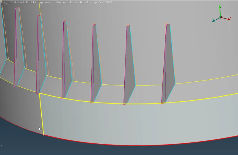
Fig 12: Complete mid surface extraction of all ribs
- Now, we start extracting the mid-surfaces for the inside teeth on the top. These are basically the same feature repeated a certain number of times, so we can extract the mid for one tooth and since these are spread out in a circle, we can Transform> Rotate this one mid to get mid-surfaces for all the teeth.
- To get the mid of first teeth we can create a curve in the middle of the teeth’s section that is coming out of the substrate using Curves> Create and then project the base con on the substrate mid using Cons> Project. Finally, we can use the Faces> New> Cons to create the mid for the tooth. This is done in Fig 13 below.
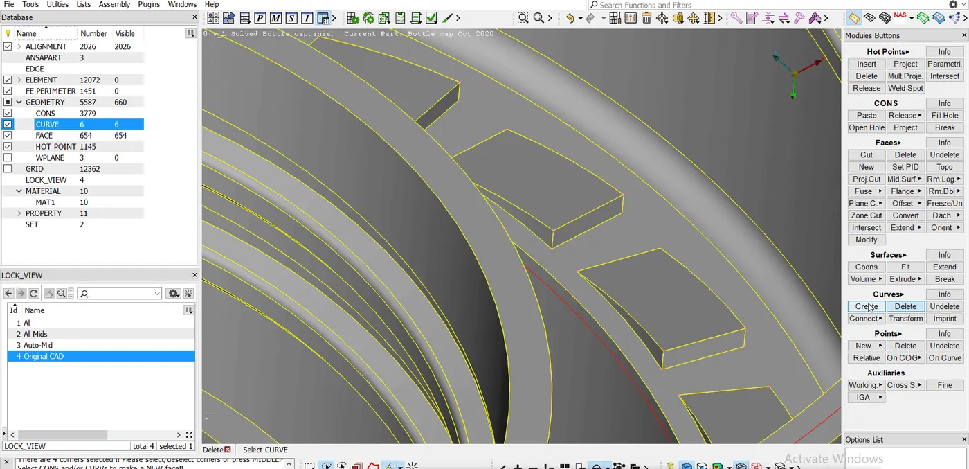
Fig 13: Extracting mid of the inside top tooth
- For rotating this mid to get the number of instances of the teeth as in the CAD model i.e. 26, we have to use Transform> Copy> Rotate. Also, this requires an axis of rotation for which we have to use Points> COG> Edges on closed perimeter edges at different heights to get two points for a vertical axis. Then, for rotating the mid, we enter parameters Steps as 25 (since one mid is already there), X as one of the COG points, dX as the other COG point and Angle of rotation as 360/26 i.e., (angle of the circle)/(number of instances of the entity to copy). This is shown in below Fig 14.
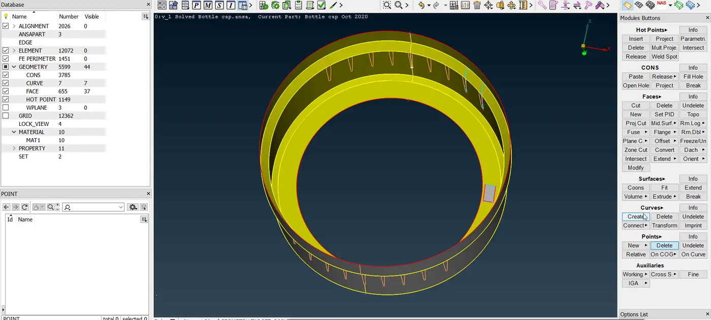
Fig 14: Copying and rotating the mid-surface of the inside top teeth
- It is now noted that the original tooth mid had intersection with the substrate and there was a triple con at their junction but the copied mid-surfaces do not have this triple con. To get this we have to project the base single con of each tooth individually on the substrate mid and then either use Faces> Topo or Cons> Paste. Topo is rather faster.
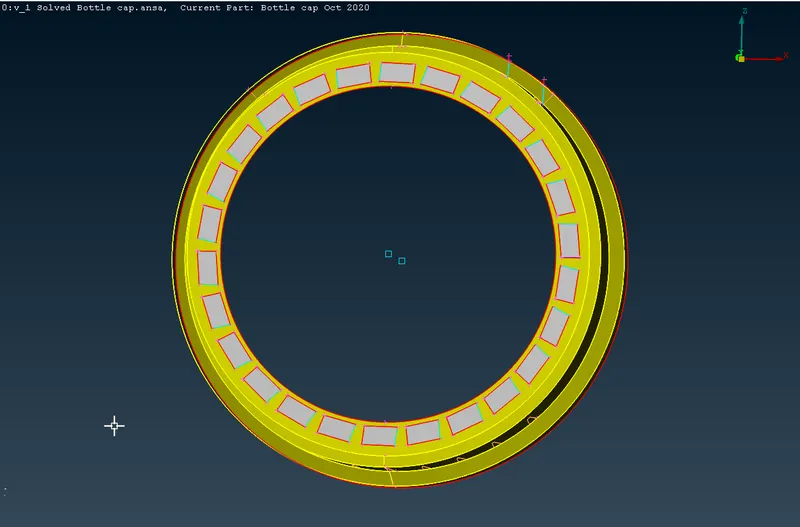
Fig 15: All teeth mid surfaces are extracted and have triple con with substrate
- We can now extract the mid-surfaces for inside bottom teeth. We can follow the same steps as followed in top teeth. So, first extracting mid of just one tooth using Faces> Middle> Single. Then using Topo to stitch the two halves of the mid together. Then we can extend the mid to the substrate as shown in Fig 16 below.
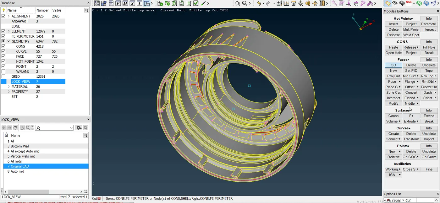
Fig 16: Extracting mid-surface for the inside bottom tooth
- It is noted that the extended surface runs beyond the substrate due to some excess height above the substrate 0.15 mm to be exact. The unnecessary excess surface is removed. There is still some excess left above the substrate, we can either trim this excess resulting in material removal from the FE, or we can Topo it and let the FE be distorted by 0.15 mm. I chose to Topo it and let it distort a little as seen in Fig 17 below.
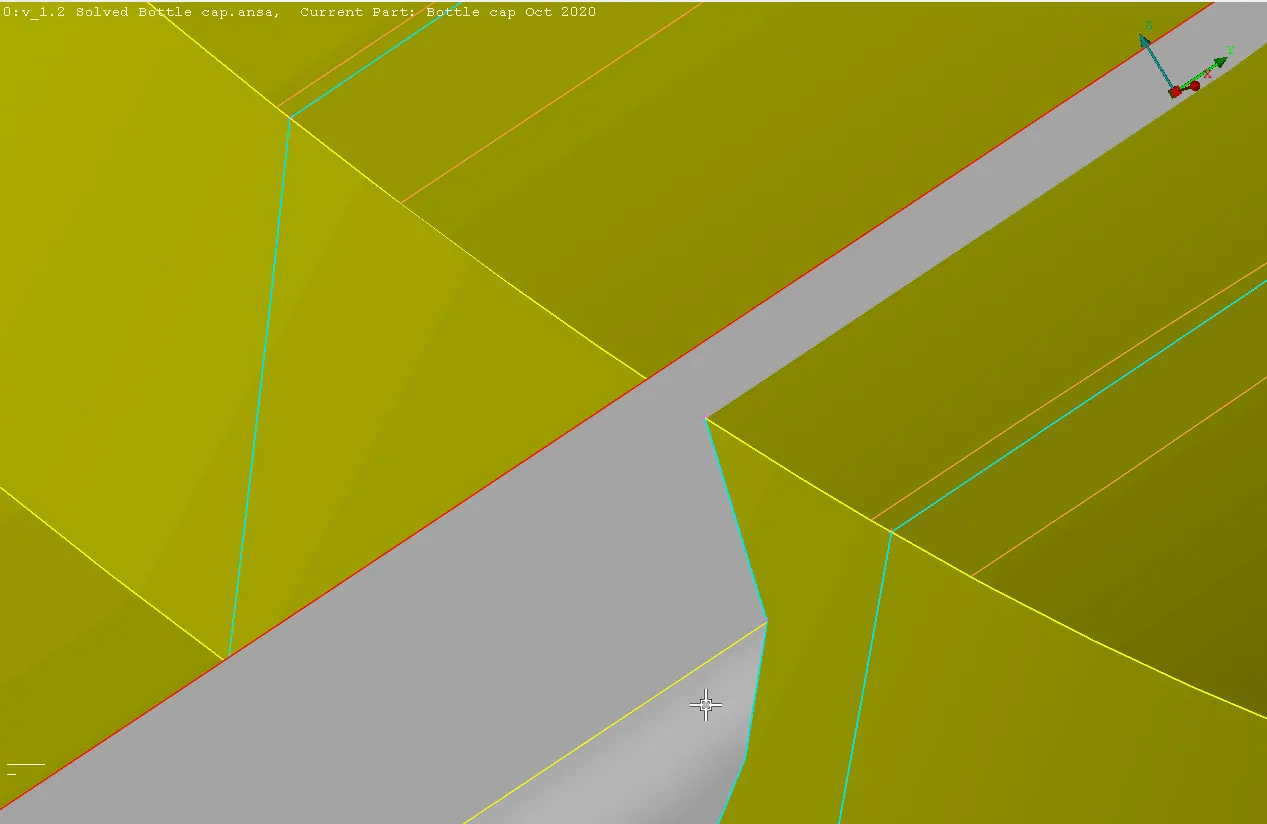
Fig 17: Trimming the excess and adjusting for rib feature
- Now, to rotate and copy this tooth mid surface, we use Transform> Copy> Rotate and put parameters Steps as 11, and Angle as (360/12).
- Again, the cons are to be cleaned up using Project and then Topo.
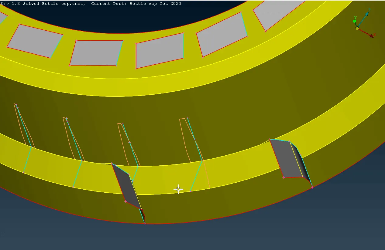
Fig 18: Mid-surfaces for all inside teeth extracted with Triple cons at substrate junction
- Now, we can start extracting the mid-surface of the top-most horizontal surface which has a number of holes and connecting links between various surfaces, as shown in Fig 19 below. First, it is ensured that the geometric cleanup of the surface is done completely and then we can use the Faces> Offset function with Offset distance as half of the surface thickness which is 1.53 mm.
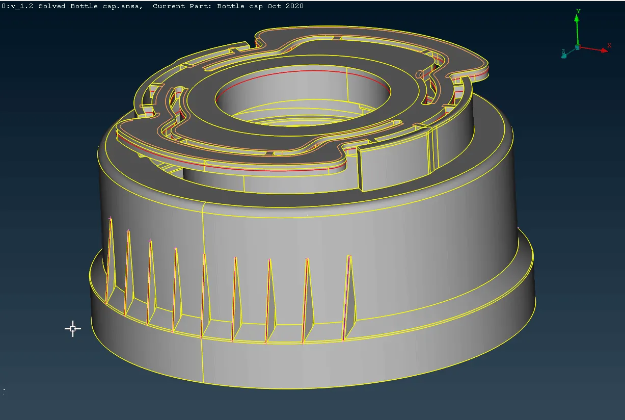
Fig 19: Mid-surface extracted for the top horizontal entity
- Next, we can work on the vertical support structures connecting the two horizontal entities. Here, we use Faces> Offset function for mid-surface extraction by first noting the thickness in different sections. It is also first ensured that the topology and geometry is cleaned and any unnecessary Cuts are suppressed as seen in Fig 20 below.
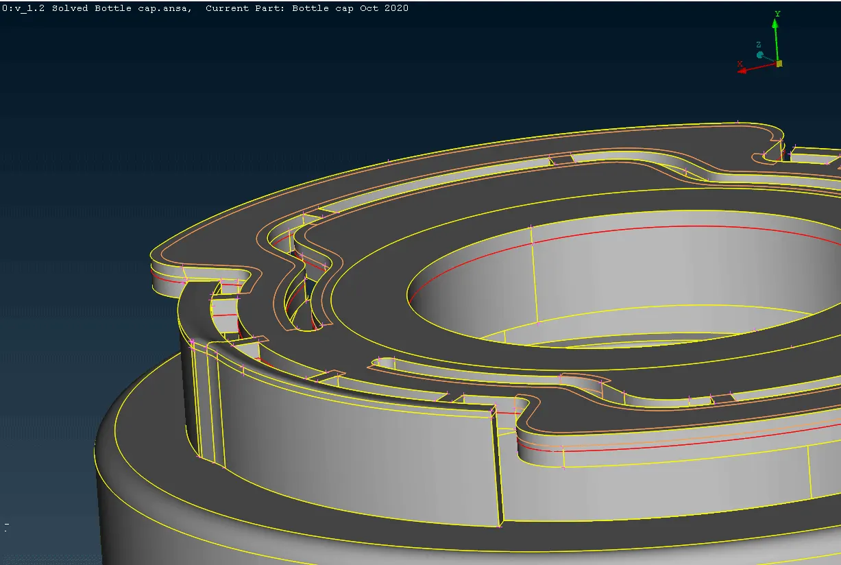
Fig 20: Suppression of unnecessary Cons/ Cuts on the support structure
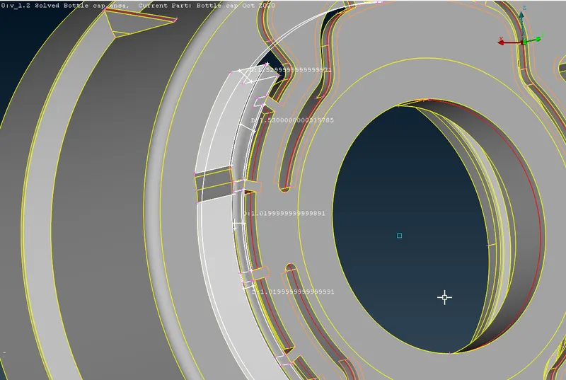
Fig 21: Thickness at the different sections of the top vertical support
- It is noted that between the two uniformly thick sections of the top support, there is a varying thickness portion where mid can be extracted using the Faces> New> Cons with the ends of the other two mid-surfaces, as shown in Fig 22 below.

Fig 22: Mid surface extraction of top support
- It is also noted from Fig 22, that the top horizontal mid-surface is not actually connected to the vertical mid of the support structure. Hence, Faces> Extend is needed to do the same. Also, the base of the vertical support mid is not actually connected to the below horizontal mid, i.e., the substrate. The extension is needed here as well.
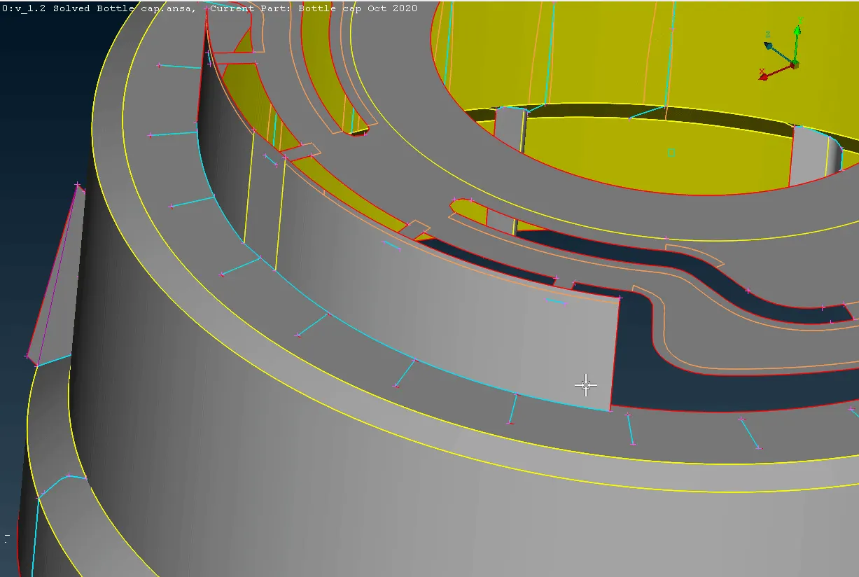
Fig 23: Extension of vertical support mid to base substrate and that of horizontal connectors to vertical mid
- Next, we can work on the top inside vertical walls of the bottle cap, both smooth and threaded as follows.
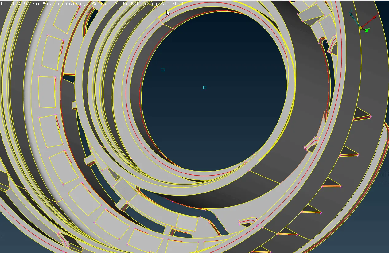
Fig 24: Mid extraction of top inside smooth vertical wall
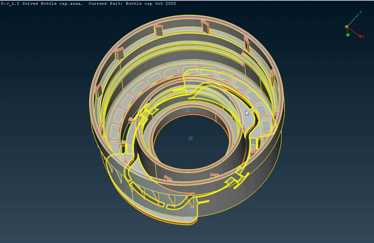
Fig 25: Mid extraction for top inside threaded wall
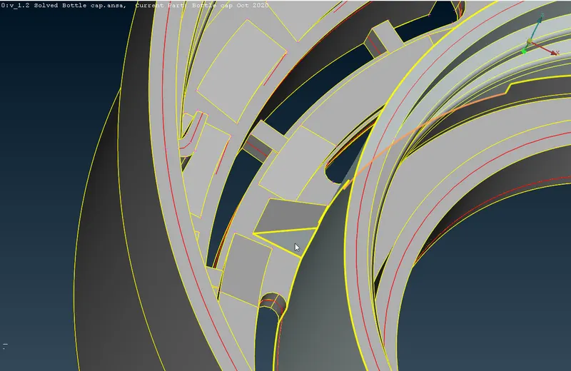
Fig 26: Rib support for the inside vertical threaded wall & extra support features on top surface from underside
- It is noted from Fig 25 & 26 that, rib supports for the threaded wall are present and need to be included in the FE. Also, extra features on the top substrate are noted from Fig 26.
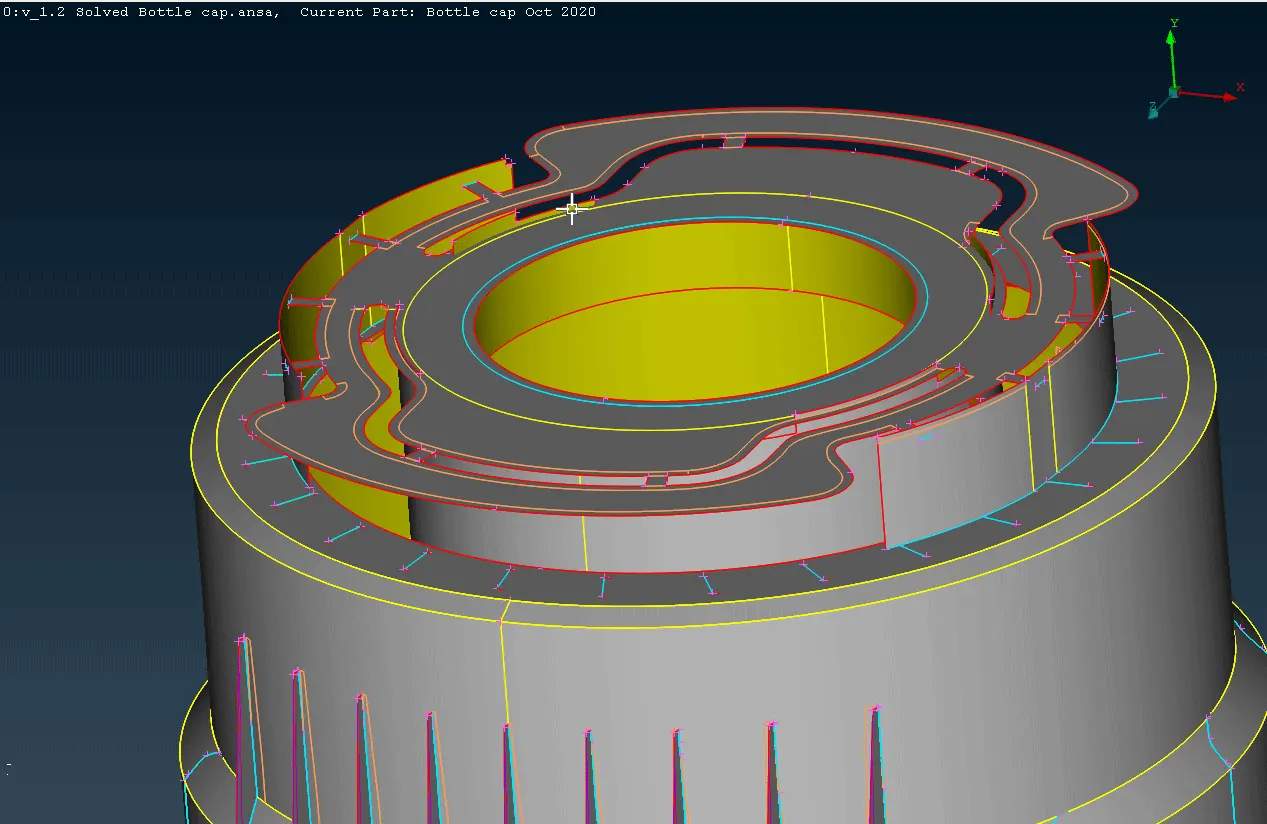
Fig 27: Top threaded wall mid extending beyond substrate
- It is also noted from Fig 27 that, the mid of the inside top threaded wall extends beyond the top horizontal substrate and needs trimming. This can be done using Faces> Intersect and then Delete.
- Also, from underside, the same mid needs extension to the top horizontal substrate.
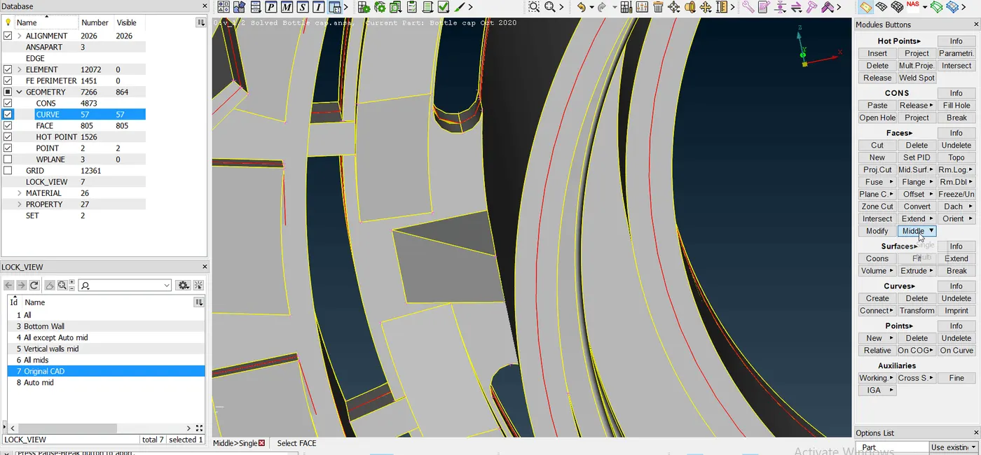
Fig 28.a: Mid extraction of rib support
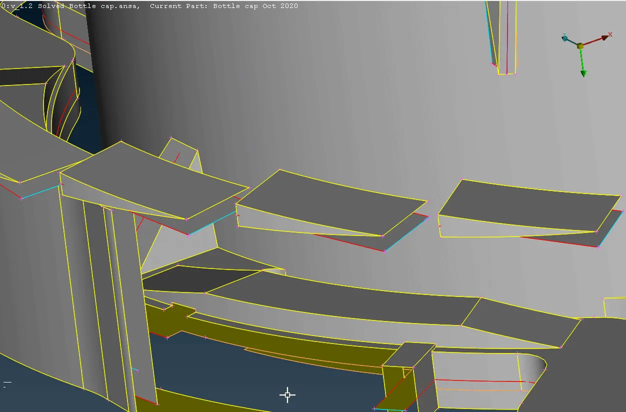
Fig 28.b: Mid extraction for extra support feature of top horizontal substrate
- Now we, can work on the screw-threads of the inside top threaded wall. To extract the mid of the screw thread, we first use Curves> Middle function on the top edges of the thread and use Auxiliaries> Fine to smooth the curve.
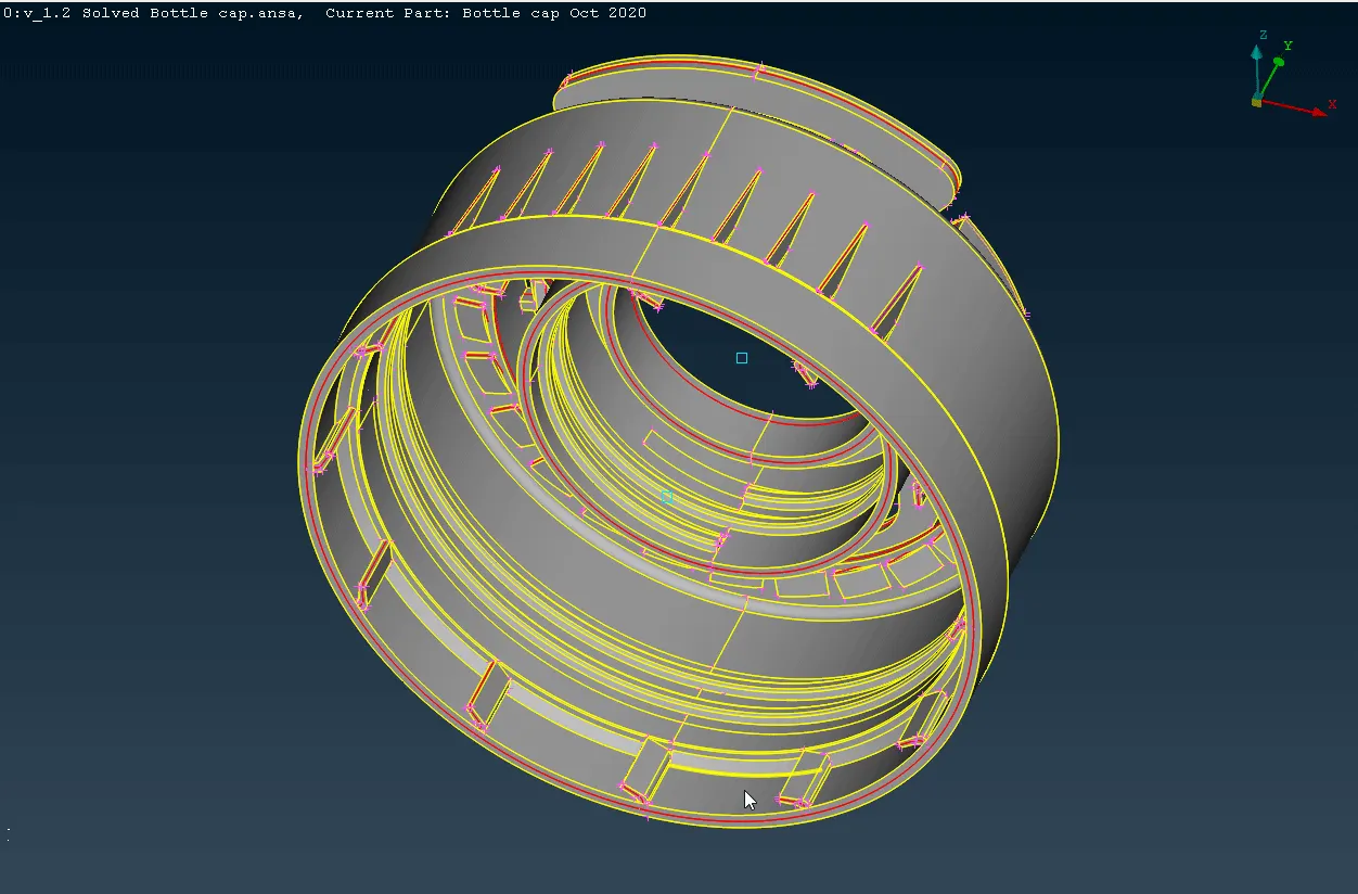
Fig 29: Creating curve in the middle of thread edges
- Project this mid-curve of the screw-thread on the substrate, i.e., the mid of vertical threaded wall. Finally, Faces> New> Cons is used to create the mid of the thread.
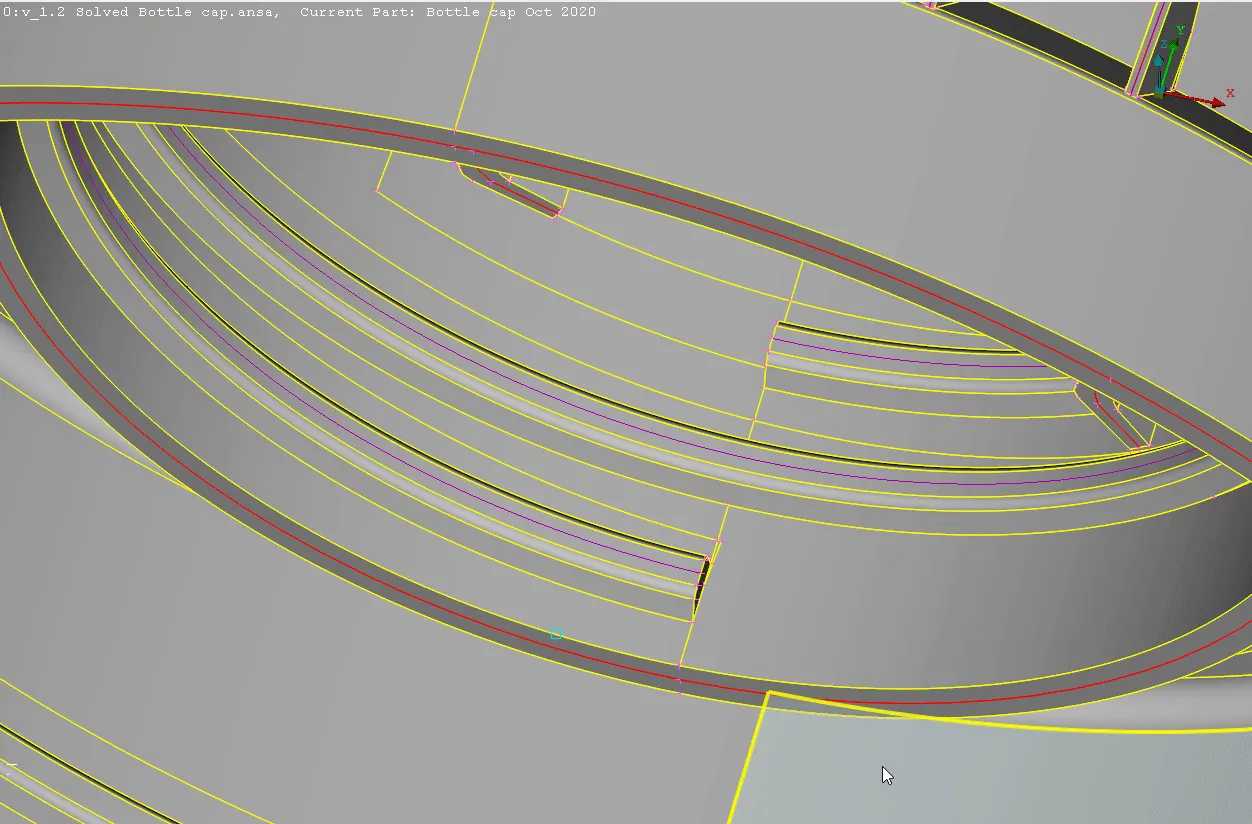
Fig 30: Curve projection and mid plane extraction for screw-thread
- The mid-surface extraction for the other screw thread can be done in the same way. It is, although, a mistake on my part to leave this for last. After having extracted the mid-surfaces for the external rib supports, the generated triple cons and extra cons on the substrate wall make it time-consuming to extract mid of the main thread in one go, thus taking more time than necessary for such a simple feature.
Fig 31: Extracted Mid-surface for the complete CAD model
5. Creation and application of PIDs for each unique geometrical feature.
- Now, PIDs are created by going to PROPERTIES> New> PSHELL> PSHELL. Here it is necessary to create unique PIDs for every entity that has a unique thickness. For, entities or sections with varying thickness an average thickness can be entered.
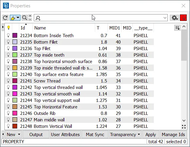
Fig 32: Creating PIDs for each entity with unique thicknesses
- PIDs can be applied to mid-surfaces of each entity by selecting a PID and clicking on Apply. After this, each geometric feature needs to be selected by Left mouse click and then confirming by Middle mouse click.
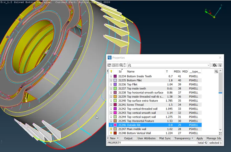
Fig 33: Applying PIDs to mid-surfaces of features
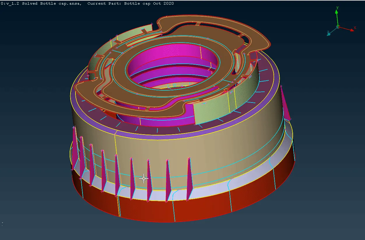
Fig 34: All PIDs applied to each feature of the CAD model
6. Mesh generation for the CAD model.
- The mid-surfaces of the given model can now be meshed but first we have to set the Mesh Parameters and Quality Criteria as per given data.
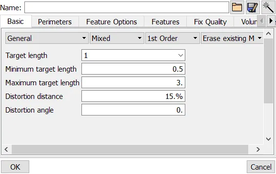
Fig 35.a: Mesh Parameters as per given requirements
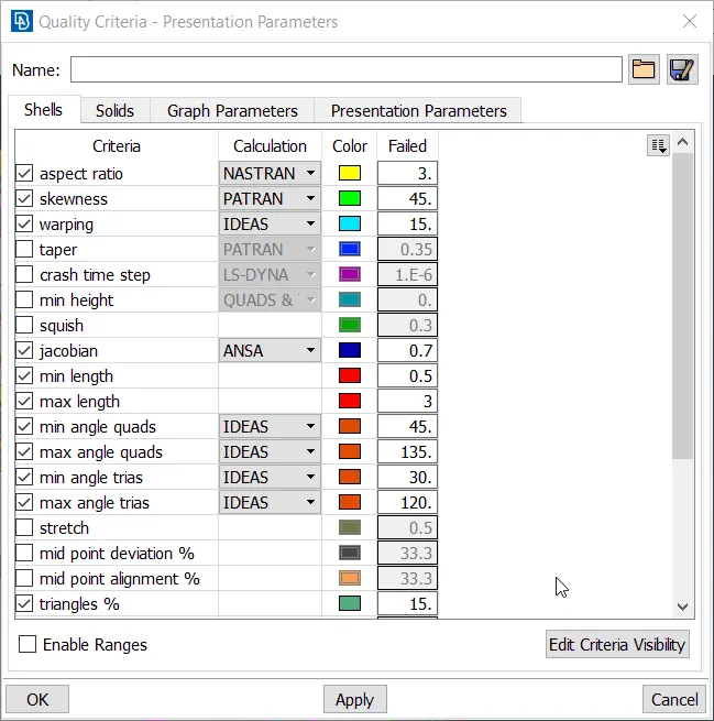
Fig 35.b: Quality Criteria as per given requirements
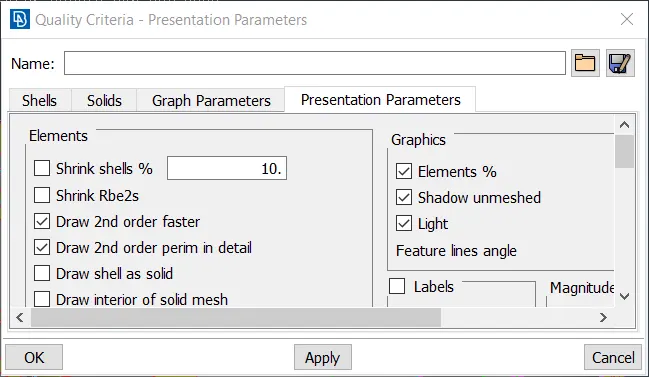
Fig 35.c: Enabling Elements% in Presentation Parameters
- Elements% is enabled in Presentation Parameters to enable total percentage of trias and the quantity of OFF elements.
- Finally, meshing of each feature of the model can be started using Mesh Generation> Best or other suitable algorithm in the Mesh module.
- Starting from the most feature rich areas on the model we can work towards simpler entities to mesh for time management. Thus, starting to mesh bottom vertical wall then the inner teeth, the fillet, the middle vertical wall, the rib supports, the inside threads, the top inside threads, the inner threaded wall and smooth wall, the support and extra feature for the threaded vertical wall, then the top inside teeth, the top horizontal surface, the top vertical supports, the remaining top horizontal face and finally the top fillet.
- The following video in Fig 36 shows the various regions of the completely 2D meshed Plastic Bottle Cap model.
Fig 36: Completely Meshed Plastic Bottle Cap Model
- Now, as seen in Fig 36, there are OFF elements present in the final meshed model, 80 OFF elements or 0.82% of all elements are OFF to be precise.These OFF elements are occurring due to unavoidable triple cons in the mid-surface of the CAD model. These OFF elements cannot be eliminated without altering the geometry or the mid-surface of the given CAD model. Thus, these are left as is.
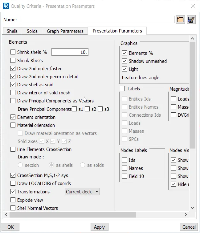
Fig 37: Drawing shells as solids to visualize the FEM as a solid
- We can now enable Draw shell as solid in the Quality Criteria under Presentation Parameters option. This allows us to visualize the FEM model as a solid.
Fig 38: Enabled 'Draw shell as solid' to visualize FE model as a solid and compared it with original CAD model
- It is seen in the above video Fig 38, that the solid shells of the FE model do overlap perfectly with majority of the original CAD except a few features, like the bottom fillet, the support ribs, the inner threads and the bottom inner teeth. This happens due to these features' varying thickness which was approximated while setting PIDs.
- Conclusion:
The Plastic Bottle Cap model was rectified of geometrical errors after which the mid-surface for the same was taken by using two techniques, namely Auto-mid generation using 'Faces> Mid.Surface> Casting' function and manually using functions 'Offset' and 'Middle' under Faces options. Of these two techniques, the Auto-mid was not generated correctly thus, manual mid was used to create the FE model. After the mid-surface extraction was done, unique PIDs were created for each entity with unique thickness and applied to the same. The mid-surface was then meshed using the given Mesh Parameters and was checked for any OFF elements as per given Quality Criteria. Most of the OFF elements were eliminated. Exactly 80 OFF elements or 0.82% of all elements were OFF in the final model. These cannot be eliminated as these are present between two or more very close triple cons. Finally, the FE model is visualized as a solid by enabling 'Draw shell as solid' and is compared with the original CAD model and areas where the FE model and original CAD don't overlap perfectly have been noted.
- Learning Outcomes:
1. Learnt about the types of geometric errors in imported CAD models and their resolution.
2. Learnt about mid-surfacing and its application in approximated 2D meshing of plastic models.
3. Learnt about the necessity of defeaturing prior to starting the meshing.
4. Learnt about different quality criteria like Aspect ratio, Warpage, Skewness, etc.
5. Learnt about identification of multiple hotpoints in the same location and its effects on the FE model as well rectification of said multiple hotpoints.
6. Learnt how to minimise the number of OFF elements in areas on unavoidably close double and triple cons. Also, to leave some OFF elements as they are since they cannot be eliminated without altering the geometry itself.