Week 6 - Creating connection for Rear door
Creating Connections for Rear door
Aim: For the given Rear door FE model, Create and Apply different PIDs for different components. And give suitable connections.
Procedure:
We already have the FE model available with us. So, now we need to give suitable connections between different components. In this model, we can give the following connections.
- Bolt connections
- Spot weld connections
- Seam weld connections
- Rigidised Connections
- CBUSH connections
Apart from this, there are so many connections available in the ANSA like adhesive joints, etc. In this model, I have used these connections except seam weld. As raw connection data is not present in the model, some assumptions and approximations are taken to make the assembly rigid for NVH simulation.
1. Bolt connections:
If we have the Bolt and nut Connection in the CAD geometry, we should provide bolt connections between the members. There are two ways to show bolt connection in FE representation.
- Manual representation
- Automatic connection
1. Manual Representation:
In manual representation, we give rigid Element connection (RBE2) for holes and then we give two-node RBE2 as the stem of the bolt. This represents the Bolt connection model. RBE2 creates an imaginary master node in the center of the hole and it is attached to slave nodes, which is created by NASTRAN Deck > elements > RBE2> many nodes or two-node RBE2. Two node RBE2 is used to connect the master nodes as the stem of the bolt. If that bolt is a hinge pin, you can free DOF also.
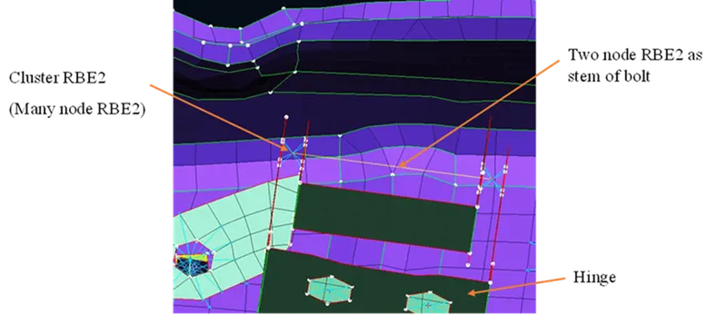
Fig 1: Manual representation of bolt
2. Automatic Representation:
For Automatic Representation, initially, we create 3D points using the option ON COG (Topo > Points> On COG) for holes. It will create a point at the Centre of the hole. Then convert the point as a bolt (Assembly manager > Covert > select the point > Select bolt option in conversion). Then to realize bolt connection, Go to Connection manager and give P1, P2, P3, etc identities and Select FE representation as Bolt and fill the options if required. It will create the Bolt and stem representation.
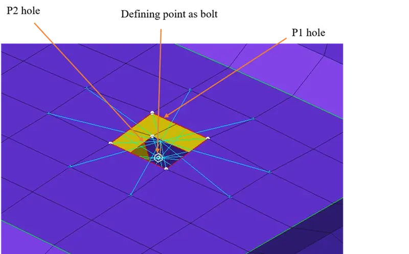
Fig 2: Automatic representation of bolt
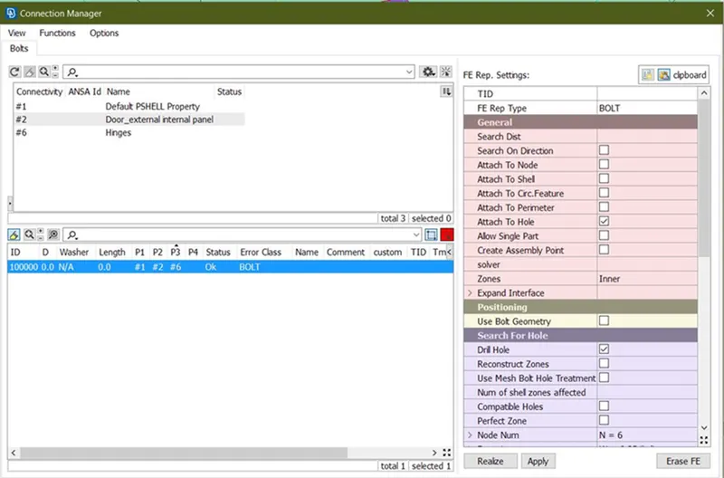
Fig 3: Connection manager of bolt
2. Spotweld connection:
For the Spot weld connection, first, we create a point using the ON COG option, then we convert the point to a spot weld point. To realize it as a Spot weld connection, we go to the connection manager and select the P1 and P2 identities and Select the FE representation as RBE3-Hexa-RBE3. And give RBE3 pin flags as 123456 to constrain all DOF. And give Psolid id and fill in necessary options. It will create the spot weld between the two parts.
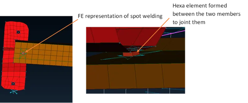
Fig 4: Representation of Spot welding
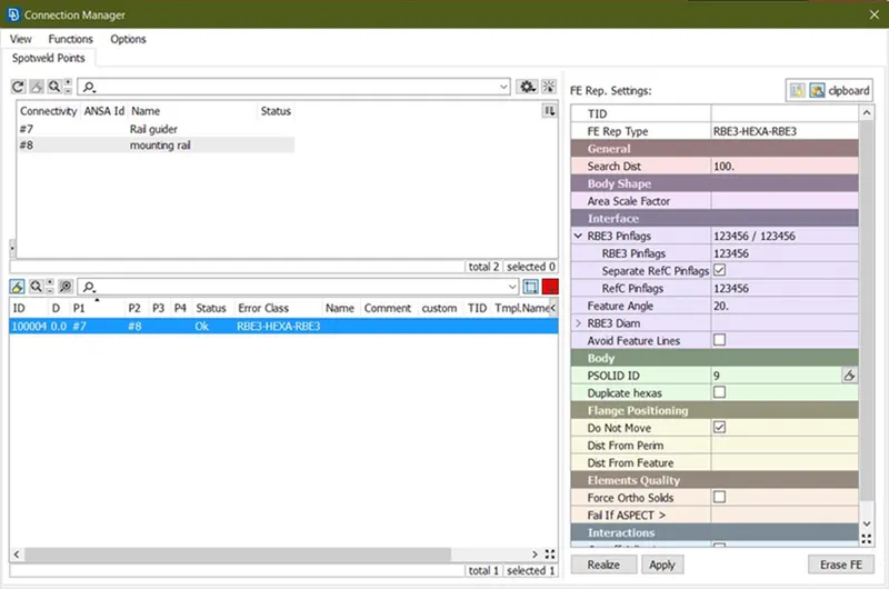
Fig 5: Connection manager for Spot welding
3. Seam Weld Connection:
For seam weld, you need the length of seam weld. This will be provided as raw connection data in 3D Cad data. Then convert con from raw weld data to curve. Then convert the curve as a seam weld line. To realize the Seam weld connection, go to the connection manager and select the seam weld curve, define P1 and P2 members. Select the FE representation as Overlap shell for parallel surfaces and Y-Joint for perpendicular surfaces. But here I haven’t provided any seam weld connections in the model. I have tried to give seam weld between stiffener rod and sheet metal holder, but the FE lines are not parallel. And I have tried the spot weld between them but it is not creating. So, I just rigidized the two parts finally with RBE2 Element.
4. Rigidized connections:
Some holes present in the model are attached to another subsystem for integration. To represent those holes, we represent them as a Rigid RBE2 element. And also, some components don’t have details for the connection. But they have to be rigidized for simulation, for those components are also connected by rigid cluster RBE2 element. We can also represent two holes for bolt connection as cluster rigid element. It does not represent a bolt connection. But in the end, both members are to be rigidized. So, we use this kind of connection. We can also use this to save time.
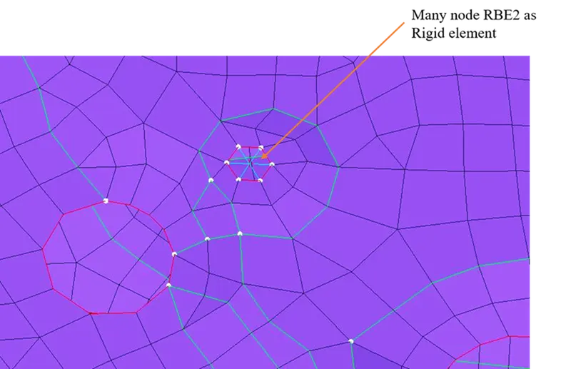
Fig 6: Representation of Many node RBE2
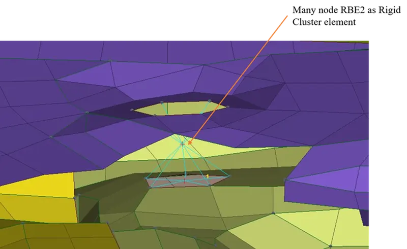
Fig 7: Representation of Many node Cluster RBE2
5. CBUSH connections:
Cbush element is generally a spring element that has 3 directional stiffness properties. we can use this for weatherstrip representation for modeling. Here we are using weatherstrips along the periphery of the window. So, take the periphery curves of the window. And the bottom side of the window has two weather strips on either side of the window. We offset the bottom curve from the window to 10mm inside. Then convert these curves into spot lines. To realize it as a Bush connection, we go to the connection manager and give the length between the bushes as 10mm approximately. And Define P1 and P2 members. And Give FE representation as RBE3-CBush-RBE3, check to keep all branches, define PID for bush and align them according to the global coordinate system.
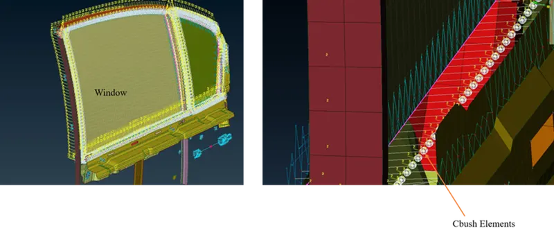
Fig 8: Representation of Cbush between window and door panels
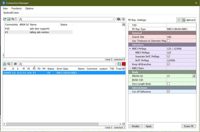
Fig 9: Connection manager for CBush connection
Providing CON MASS:
For vibration analysis, Mass is an important factor. And we do not add all the components in the system. We simply add the mass of that subsystem.
Natural Frequency, `ω_n=√(K/M)`
K= Stiffness
M= Mass
Here I am giving mass for the door handle. I am assuming the door handle weight is 100 grams. In ANSA, we should give the mass in Tons, so I am giving 0.0001ton as the mass of the door handle. To give the mass first we create the master node at the COG of the door handle. For that, I’m taking reference of the mounting holes for the door handle. We create rigid elements (Many node RBE2) at the mounting holes. Then we connect the two master nodes of mounting holes with Many node RBE2, which will create the master node in middle. Thus, we create the point at COG. To give mass, Nastran deck >Elements > CON Mi > CON Mi2 > nodes > Select the master node and give mass.
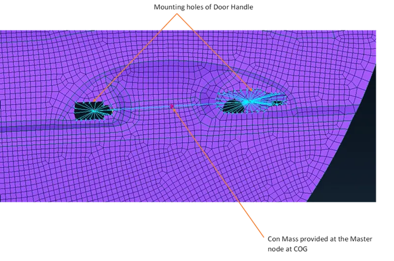
Fig 10: Representation of CON Mass
Learning Outcomes:
- I have learned how to give connection representation in CAE for the bolt, Spot, and seam weld connection, and also Cbush connection representation.
- Learned giving con mass.
- Learned mechanisms involved in the car door.
Result: Achieved all the connections for the given rear door.
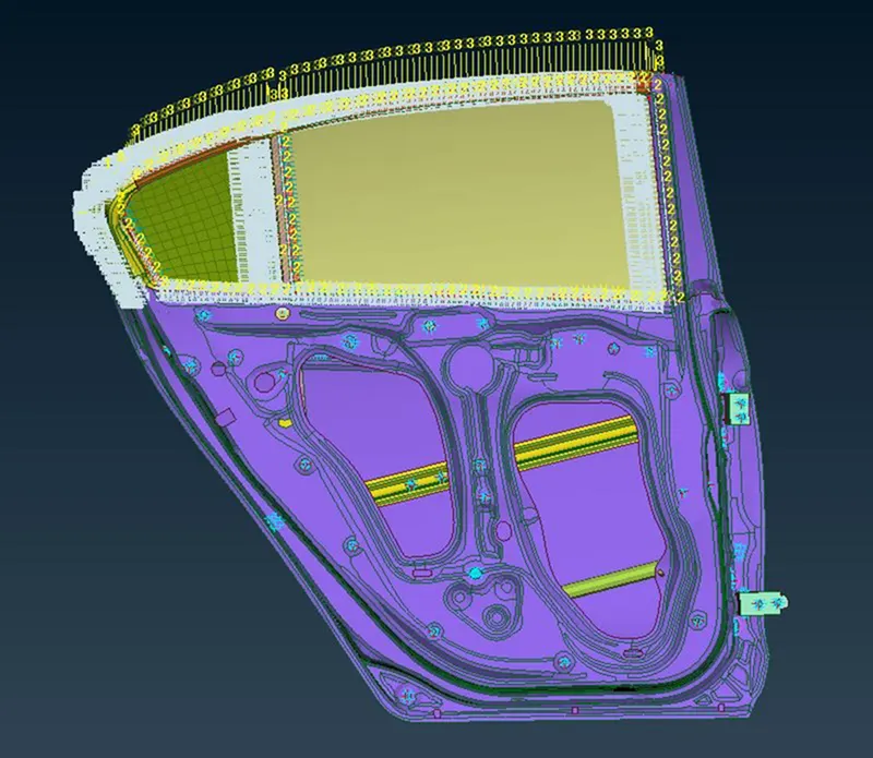
Fig 11: Final model side door after giving connections