Week 3 - 2D meshing for sheet metal
2D-Meshing of Sheet Metal
1. Aim: For the given Hood model, after checking the geometrical errors, take the mid surface for all the components and mesh the mid surfaces with the given element Quality criteria.
2. Procedure:
To do the mesh below procedure is followed
- Checking CAD topology
- Mid surfacing
- Defeaturing
- Shell mesh
- Element Check and Improve mesh quality
1. Checking CAD topology:
In this step, we check CAD geometry. This includes, all surfaces being stitched properly, checking any triple cons available, and checking any broken surfaces are present. These geometrical checks are automatically done and solved by ANSA by the geometry checks option in the Tools tab. ANSA can fix some errors, but some issues can be solved manually. Most errors can be detected by ANSA, but you have to ensure manually all the surfaces are good. There are 4 parts in the Hood model assembly which is given. We will do the mesh one by one.
- Hinge reinforcement extract 1&2
- Latch reinforcement extract
- Outer Extract
- Inner extract
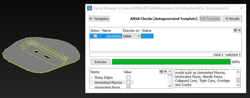
Fig 1: Geometry checks of Hinge reinforcement
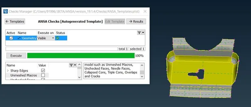
Fig 2: Geometry checks of Latch reinforcement extract
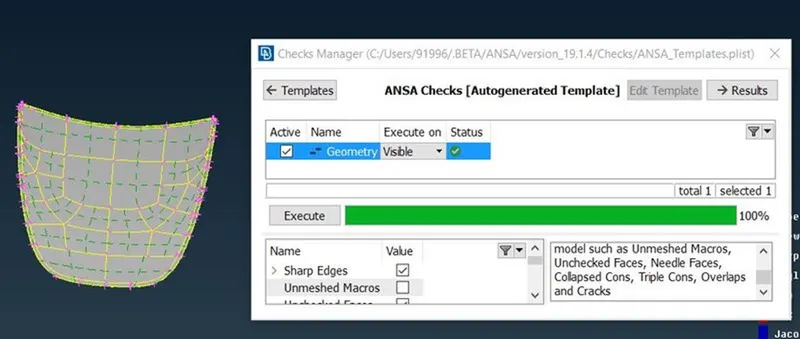
Fig 3: Geometry checks of Outer extract
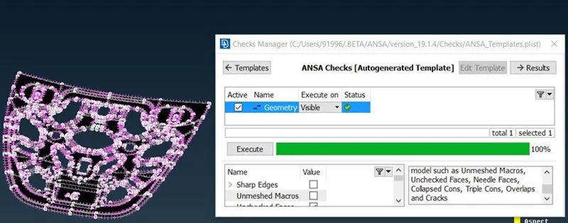
Fig 4: Geometry checks of Inner extract
If you found any triple cons, and ANSA can’t solve the problem, release the cons and do the TOPO operation manually. If you found any broken surfaces, use delete option in faces menu. For broken surfaces use the delete option in the faces menu. And create new face in the TOPO module.
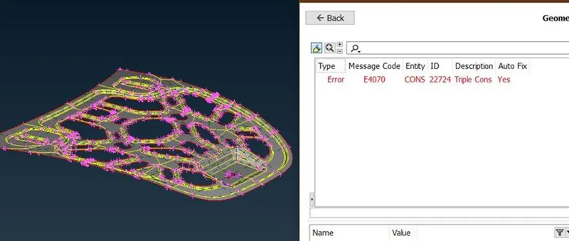
Fig 5: Geometry checks of Inner extract
2. Mid surfacing:
When the geometry checks are done go for mid surfacing. There are two ways to obtain the mid surface. One is Auto mid option and another one is manual mid. For Auto mid, object should be closed volume. Auto mid assigns thickness automatically when creating mid. Sometimes auto mid option failed to generate mid surface, in that case, we go for manual mid.
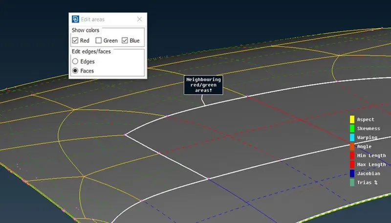
Fig 6: Error in creating mid by Auto Mid option (Outer extract)
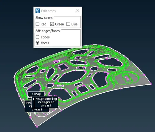
Fig 7: Error in creating mid by Auto Mid option (Inner extract)
When you are going for mid, check the thickness of part at different places and confirm the thickness is uniform. If we are going for manual mid, assign PID and assign thickness to that mid surface.
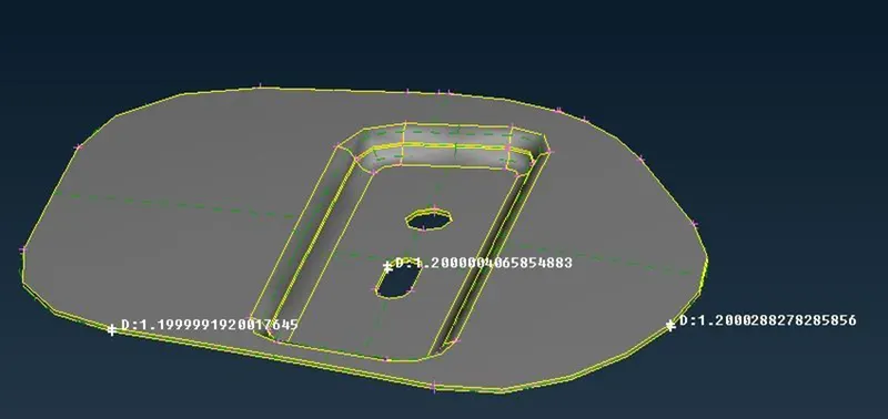
Fig 8: Checking the thickness of component at different locations of the part
For parts Hinge reinforcement extract 1&2 and Latch reinforcement extract, I used the auto mid option to extract mid surface. For Parts Outer extract and Inner extract, I did manual mid. Because in the Inner and Outer extract, I could not able to do auto mid, you can see in the figure.
3. Defeaturing:
If the distance between the cons is less than the minimum element length criteria, we can go for defeaturing. Because those elements formed at those cons are failed for minimum length criteria. And always capture the fillets by more number of rows. I defeatured most of the fillets and hems, and unwanted cons. I joined the unwanted cons mostly to avoid more number of surfaces and also they complicating our mesh.
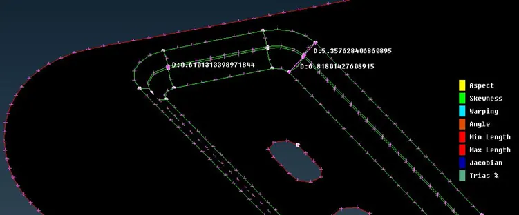
Fig 9: Minimum distance between the cons
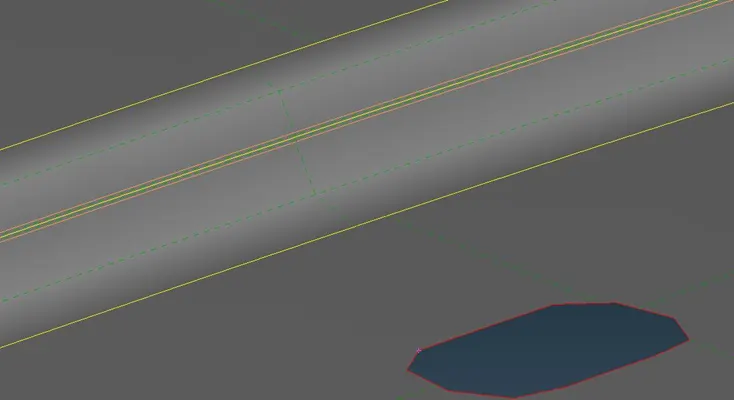
Fig 10: Defeaturing
You can see the distance between the cons is 0.6, in fig 10, orange oval. This is formed because two edge radiuses are not meeting. At this location, elements formed are failed for minimum length criteria. You can solve this issue in two ways, one is ing continuous con around the geometry at the middle of thickness 0.6 or another one is you can remove one of the two cons forming 0.6mm thickness of wall.
4. Shell Mesh:
Before doing mesh, we have to give the quality criteria and mesh parameters. We can give the quality criteria by function key F11. And give mesh parameters in the utilities Tab.
Quality Criteria:
|
S.No |
Quality Criteria |
Value |
|
1 |
Target/Average length |
5 |
|
2 |
Minimum Length |
2 |
|
3 |
Maximum Length |
7 |
|
4 |
Aspect |
3 |
|
5 |
Warpage |
15 |
|
6 |
Skewness |
45 |
|
7 |
Jacobian |
0.7 |
|
8 |
Minimum Quad Angle |
45 |
|
9 |
Maximum Quad Angle |
135 |
|
10 |
Minimum Tria Angle |
30 |
|
11 |
Maximum Tria Angle |
120 |
|
10 |
Tria Percentage |
15 |
Mesh Parameters:
|
S.No |
Mesh Parameters |
Value |
|
1 |
Average length of element |
5 |
|
2 |
Minimum length of element |
2 |
|
3 |
Maximum length of element |
7 |
And in the mesh module, in the perimeter tab, give perimeter and macro length according to the quality criteria. Here I have given the average shell element length is 5. This will adjust the nodes on the perimeter and macro area according to the value given. We can use the join command in the macros tab, to join surfaces or to remove unwanted cons.
I meshed all components using the options Best, Reconstruct, Smooth, split, Paste in the mesh module. For hinge reinforcement1&2, I used the transform option in utilities tab, because they are symmetrical parts. And also, inner extract is a symmetrical geometry, so I did mesh for half the component and copied it to another half using the symmetry transform option. I deleted most of the cons in Outer extract and Inner extract because it is creating more surfaces and complicating the mesh also.
5. Element check:
The element quality criteria which we are given will check the mesh whatever we are doing. ANSA will show whichever element is failing our given quality criteria.
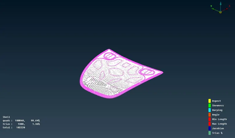
Fig 11: After completing meshing
3. Learning outcomes:
- I learned how to use the options split, paste. And where to use them. When using split by edges, I used most of the time polygon cut.
- Rotating quads are formed by two trias.
- I learned how to use symmetry option; Still want to find out what the other tools present in it.
- Most of defeaturing places are fillet regions.
- We can also defeature, using Join command in mesh module.
4. Conclusion:
Obtained shell mesh for the given components. Total no. of elements obtained are 1,02,228 elements. No off elements present. So, these number of elements will try to capture the entire surface of all parts.
Fig 12: After finishing of meshing
Total Elements: 1,02,228
Quad elements: 1,00,840
Trias: 1388
Tria %: 1.3