Week 6 - Creating connection for Rear door
Objective-To perfromthe connection of the rear door of the car with different connectors techniques.
procedure-
input the files rear door in to the ansa,on opeining the model we found the model is in single pid.
2.Connections
RBE2 connection:
1.RBE2 SINGLE cluster connections-in this type of RBE2we provide connections to two or more holes on two or more surfaces which are neaer to each other and lock their in all axies and all degrees of freedom so that they cant move in any direction which makes rigid during the noise vibration analysis in nastran,
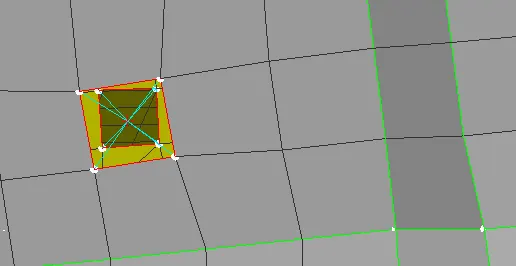
2.RBE2 spider connection- in this type connection we provide connection to the one hole which is present on model we make it rigid in all axies which avioda its movement duribg the noise and vibration analysis.
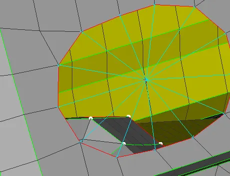
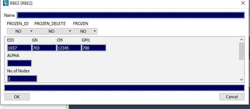
3.RBE2 TWO NODE CONNECTION-in this type we provide connection in places where the door hinges are present in the model.we select two master nodes for creating the this type of connection. to get the moment of the door along the global axies z axies we lock the dregree of freedom to only 5 axies in the cm of the info option.
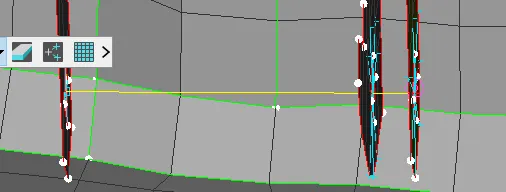
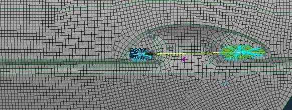
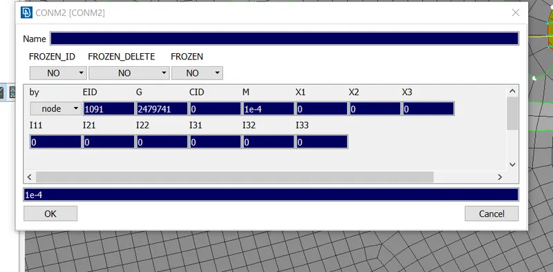
4.RBE2 connection for the door-in this type of connection in the door handle by providing the spider connection of the two holes of the door handle and then connecting the two master nodes of the spider connections to form COG then we provide con mass to cog uiing the nodes option present in the conm2 in the conmi option.
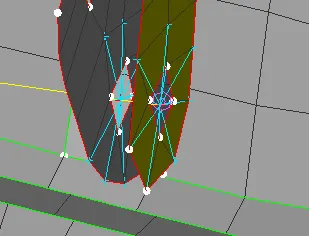
Bolt connection-In this type of connection we provide connection to wherever the bolts are goinhgbto be fitted in the rear door i.e near the hihges we first crete the 3d points by creating the points using on cog and we convert the 3d points to the bolt washer point using the convert after that we go thr conert manger option and slect all waher points and then we press middle button in connection list we define parts for which we provide connection uing the F1 tab and we provide zone as in /out in the fe resprentation and we reliase and we apply.
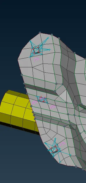
Spot weld connection - we create the 3d points using the on cog after creting the points we convert the 3d points to the spot weld points.after converting in to spot weld points after middle clicking on the spot weld points in the convert manger we have three list fe resprentatin ,connection resprentation in connction resprentation we select the parts between which we provide spot weld connections. and in the Fe resprentaion we provide Fe type presentation as RBE3 - HEXA-RBE3 and we give seach distance of 20 after that we reliase and apply.
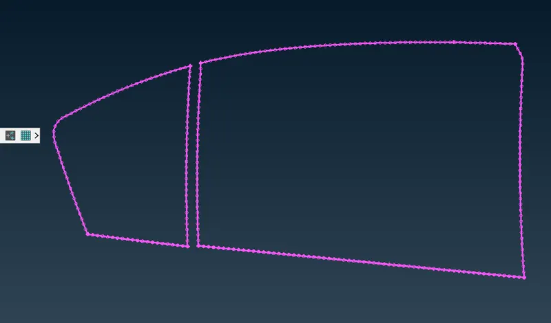
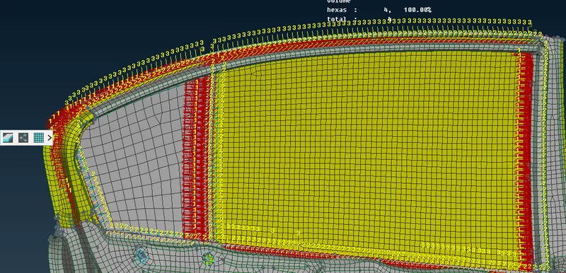
window bushing connection- in this type of connction we proivide connection to wiondow we take curves from the windows which include the fixed one near the c pillar andvthe sliding window near the c piullar using the feat to curve option then we convert curves in to spot lines usin the convert optrion . we then go the connection manger we have 3 tabs connectvity list,connection list and the Fe rtersprentation settings. we go the connection list and we proceed to give connection for which parets we want using the F1 tab and in the Fe resprentation we select the tpe as RBE3-CBUSH-RBE3 in that we provide search distance and tick on the all branches and we provide the distacve bewteen the bushes in the connectvity list and then we apply and we reliase.
After that we go the C bush elents and see that they all are oreiented with resoect to mthe vector direction.therefore we we change it with respect to the local cordiates by right click on aall c bush elemts and then give modify after it a new tab opens and we go for new modificartins where we provide orient as the modification and align with respect to the cordinate point as 0 then give ok. and we obtain all c bush elents aligned in same cordinate axies.