Week 6 - Creating connection for Rear door
Aim: Create connection to the given Rear door FE model.
Objective: The connection of weld spot and spot line is deployed on the finite element model which is given by using the RBE3-Hexa-RBE3 and RBE3-CBUSH-RBE3 respectively. The property of the given FE model is assigned individually to the parts. The rigid body element of RBE2 elements are cluster RBE2 and two node RBE2 used for suitable connection to the door.
Procedure
- Download the given file and open the file in the ANSA software.
- The model with finite element (FE) is taken and oriented to grey color on the exterior.
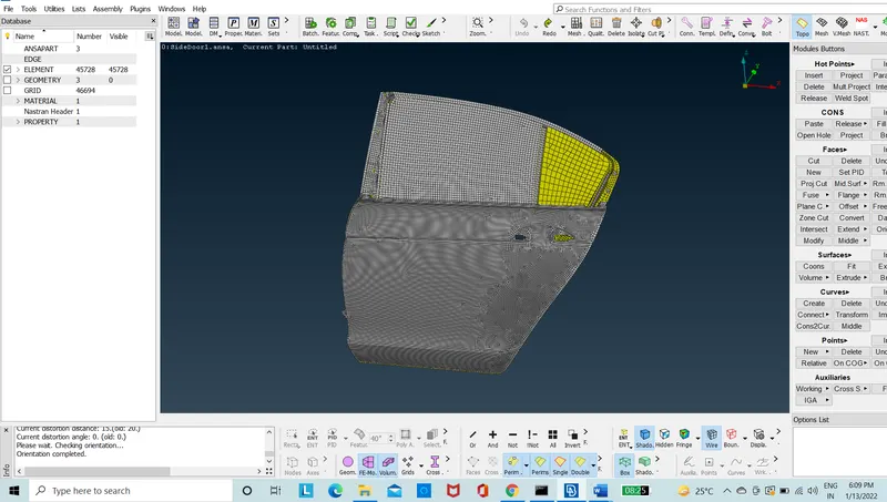
Figure 1: Before Orientation
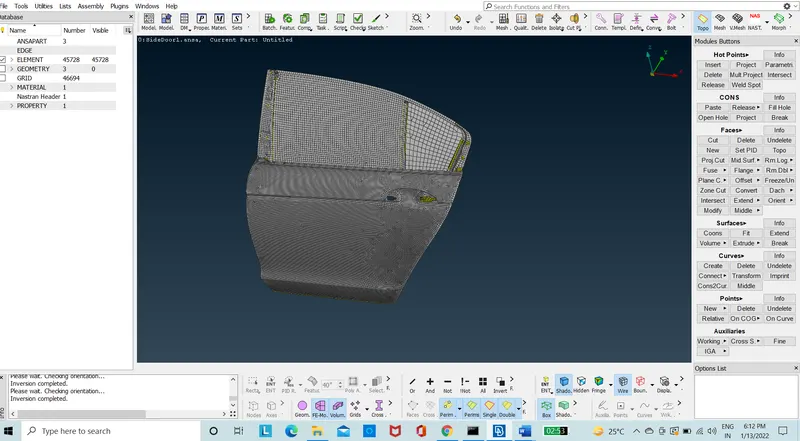
Figure 2: After Orientation
- The elements are chosen with new property ID to be assigned to so that it can be recognized as different parts in the creation of weld spots or spot line connection.
- The elements are chosen and using “set PID” option in macros of the mesh module the new properties are assigned individually on the parts.
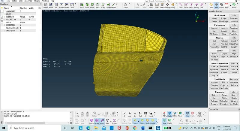
Figure 3: Before Property Assignment
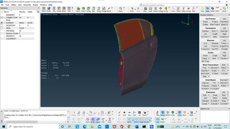
Figure 4: After Property Assignment
- The connection of the “RBE2” elements are taken from the “NASTRAN” deck module in the elements option and assigned at the door hinge using the cluster with option of many node RBE2. Mass is assigned on the handle of the door with conmi option.
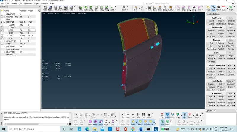
Figure 5: Model with RBE2 and CONMASS
- The door hinge with two node RBE2 is connected to the cluster to create the bolt stem.
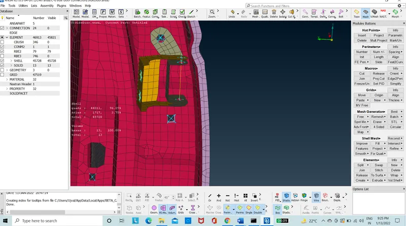
Figure 6: Model with Two Node RBE2.
- The part that needs to be weld at spot is taken and COG point is created using the points option in the topo module.
- The point is then converted individually by 3D point to weld spot using the convert option which is in “assembly” of tool bar.
- The point is then realized using the connection manager where the point is assigned with RBE3-HEXA-RBE3 connection.
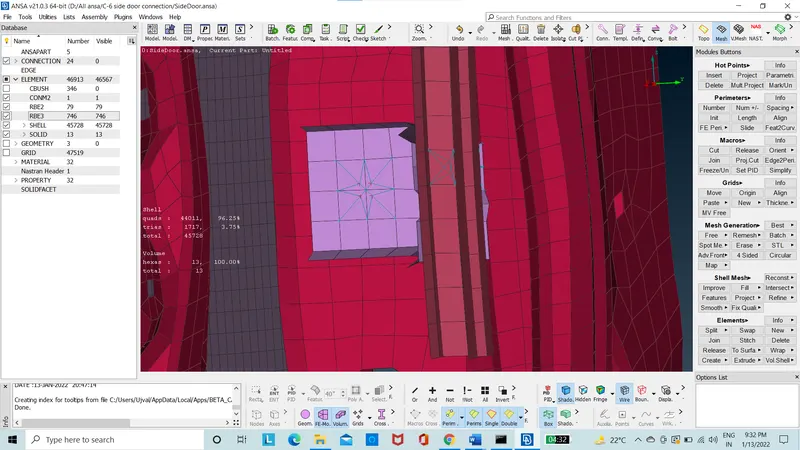
Figure 7: Model with RBE3-HEXA-RBE3
- The window of the door was rigidized.
- The curves are created on the window using the “feat2curv” in the perimeter option of the mesh module.
- The Curve is then converted to spot line individually using the convert option which is in “assembly” of tool bar.
- The Curve is then realized using the connection manager where the point is assigned with RBE3-CBUSH-RBE3 with the new solid property is assigned to connection.
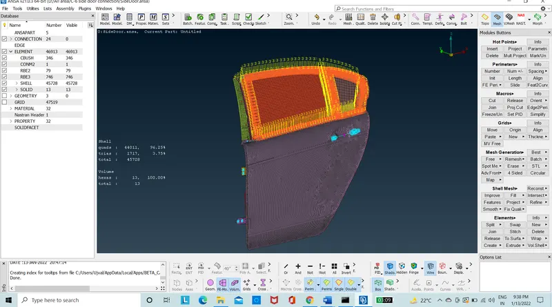
Figure 8: Model with REB3-CBUSH-REB3
- The CBUSH is the oriented to the global coordinate using the modify option where the CID is set to ZERO.
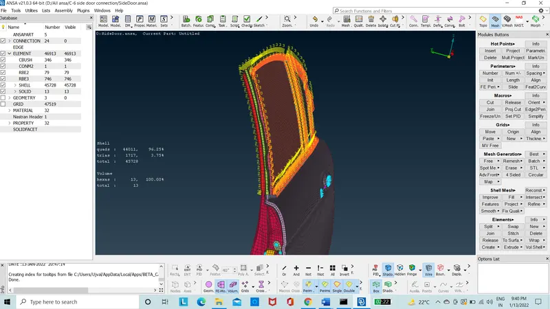
Figure 9: Model with RBE3-CBUSH-RBE3 with Global Coordinate Orientation
Conclusion: The connections is deployed to the rear door with the rigid body elements using RBE2, RbE3-HEXA-RBE3 for weld spot and RBE3-CBUSH-RBE3 for spot line will rigidize the finite element model of rear door for NVH analysis.
New things learnt:
- To assign RBE2 elements.
- To assign RBE3 elements.
- To use connection manager option.
- To use weld spot.
- To use spot line.
- To use cluster and two node RBE2.