Week 6 - Creating connection for Rear door
Creating connection for Rear Door
AIM:
To create and apply different PIDs for different components and perform suitable connections for given Rear Door in ANSA Preprocessor.
PROCEDURE:
There are 2 steps to be followed for connection deploying these are-
- Creating PIDs for different components.
- Deploying connections wherever required.
Let us understand the steps mentioned above one by one.
1. Creating PIDs for Different Components:-
Firstly, When model is opened in ANSA we get the whole model assigned in a single PID so different property IDs are assigned to different parts of the model. It is important because while deploying connections, PID definition needs to be given for connecting parts.
Property Manager > New > Apply > Select appropriate part
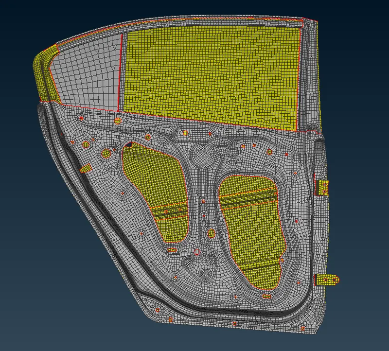
Fig: FE Model
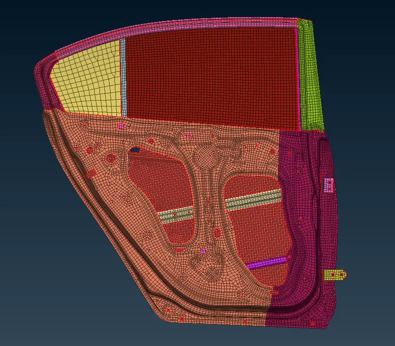
Fig: PIDs Assigned
2. Deploying Connections Wherever Required:-
There are several types of connections used for different components like Rigid element connection, Bolt connection, Door hinge connection, Concentrated mass connection, Spot weld connection, Seam weld connection, C-Bush connection etc.
Rigid Element Connections:-
These connections are used here for restricting any kind of feature movement and treating it like a rigid entity. This connection is having one master node at COG of the feature and number of slave nodes around the master node. Master node is connected with slave nodes with the help of web kind of a structure.
DECKS > NASTRAN > ELEMENTs > RBE2
->RBE2(Rigid Body Element) element is used to deploy this connection with option of using it with Many Nodes or Two Nodes and many nodes option is used here to deploy rigid connection for components.
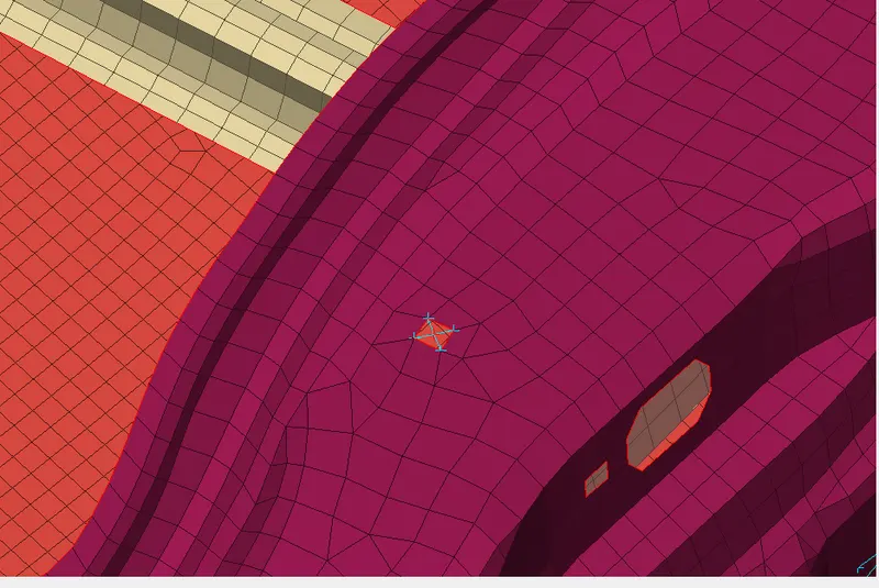
Fig: Rigid Element Connection
->Cluster Method of connection is used to connect more than one entities with the help of selected nodes. This connection creates a cluster of blue lines connecting slave nodes to one master node.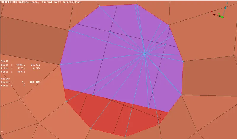
Fig: Cluster Connection
Bolt Connections:-
Bolt connections are used to connect holes together. In order to create a bolt connection, a 3D point is created at the COG of one of the holes using TOPO Module > Point > Select inner perimeter of the hole.
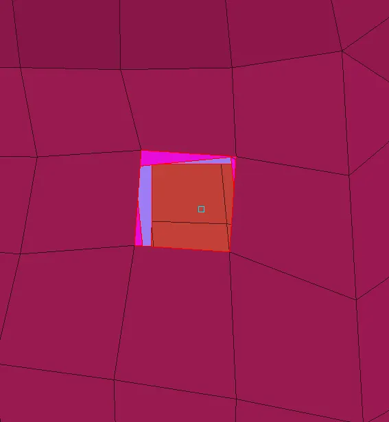
Fig: 3D Point Created
->After creating the point, the point is to be converted into a bolt point. For this, the following procedure is used.
Assembly > Convert > 3D Points > Select the point > Bolt > OK
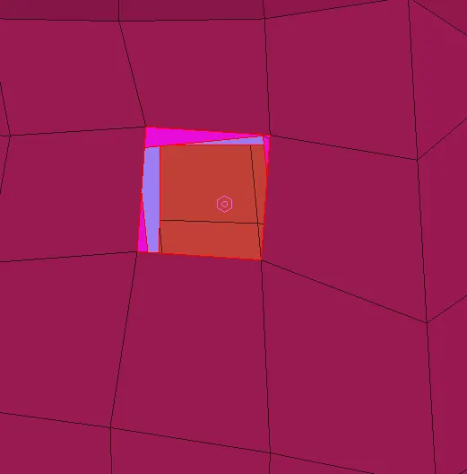
Fig: Bolt Point Created
->Now to realise the connection created Go To Assembly > Connection Manager > Select the bolt point > Middle mouse click. This opens up the connection manager tab, now define the parts to be connected with right click On P1,P2,P3_ _ _ and change the connection type from none to BOLT then define required values like search distance zones etc. and click on Apply followed by Realize.
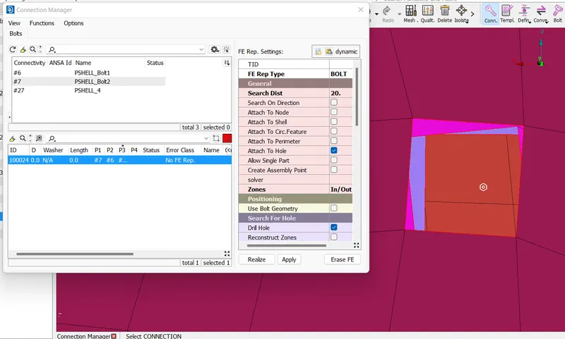
Fig: Connection Manager
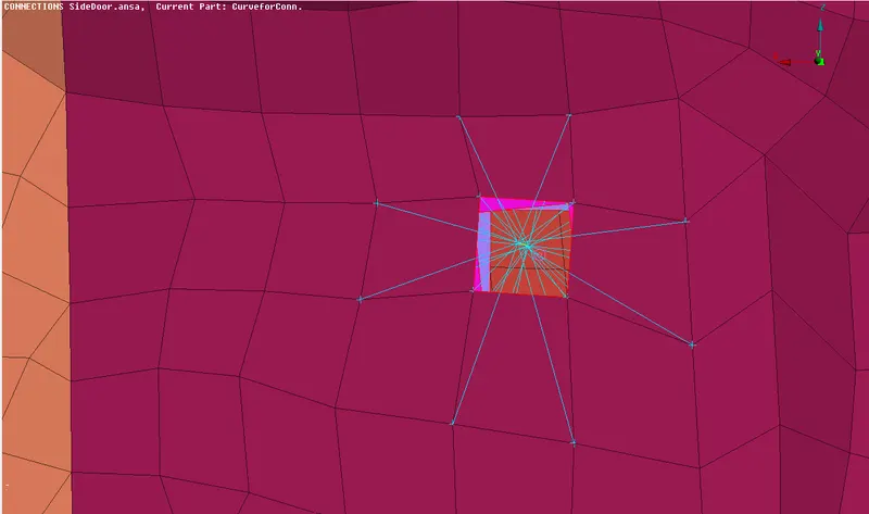
Fig: Bolt Connection Deployed
Door Hinge Connection:-
Door hinge connection is used to connect the door of the car to the car body, Many Nodes and Two Nodes both options are used in this connection which is a RBE2 element connection also while creating this connection, the door is allowed to rotate around the Z Axis by deleting the 6th DOF and keeping the other five DOFs in property card of the two nodes stem connecting two many nodes RBE2 elements shown in orange colour.
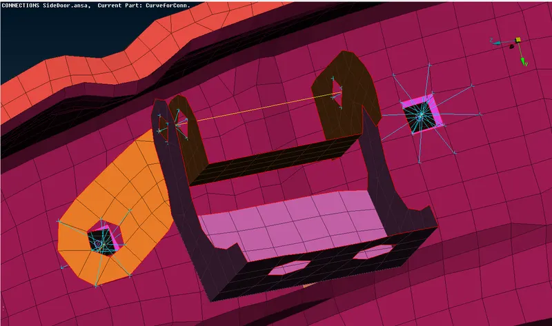
Fig: Door Hinge Connections
Spot Weld Connection:-
Spot weld connection is a point connection used to connect two sheet metal components at specific area using pressure and heat this connection is a type of RBE3 elements having slave nodes surrounded by master nodes that is the vice versa of RBE2 elements forming weblike structure to connect master nodes to slave nodes.
->To create spot weld connection first of all 3D point is created at the COG of the element to be connected, now this 3D point is converted into a spot weld point using following procedure-
Assembly > Convert > 3D Point > Select the point > Spotweld Point > OK
->Now the connection is to be realised for this the procedure adopted is exactly same upto defining the parts and then select the connection type from none to RBE3-HEXA-RBE3, then define the required values like Search Distance, RBE3 Pinflags, PSOLID ID etc. and click on Apply followed by Realize.
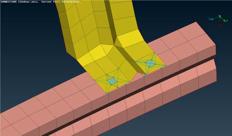
Fig: Spot Weld Connections
Seam Weld Connection:-
To define a seam weld connection, Firstly we have to define a seam weld line. Whenever we are provided with cad data including a seam weld connection, it is called raw connection data from which we have to re-enter the data that can be converted into a seam weld connection.
In order to start we have to check the length of seam weld deployed in cad geometry And this length is taken as curve using the Cons2curves option and this curve is then converted into a seam weld line which is further realised to get a seam weld connection.
->In this case we are only provided with the FE so Feat2Curves option is used to get a curve from the feature which will be converted into a seam line.
Assembly > Convert > Curves > Select the curve > Middle mouse click > Seam Line > OK
->Now this seam line is to be realised as a seam line connection with the help of connection manager for this Go To Assembly > Connection Manager > Select the seam line > Middle mouse click. This opens up the connection manager tab, now define the parts to be connected with right click On P1,P2 and change the connection type from none to OVERLAP-SHELL to connect two parts parallel to each other otherwise select the Y-JOINT-SHELL to connect parts at any angle. Define required values like Search Distance, Base Sheet, Step Length, Width, Weld PID etc. and then click on Apply followed by Realize.
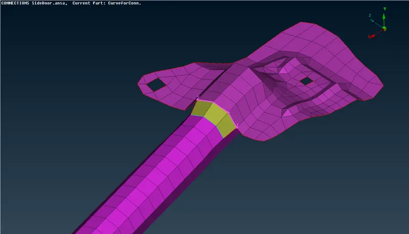
Fig: Seam Weld Connection
Concentrated Mass Connection:-
This connection is used to define the door handle which is physically not present on the outer panel of the door FE.
->Handle connection is defined by using two RBE2 elements connected with the help of another RBE2 element having concentrated mass at its master node in Tonnes. For this create RBE2 Many Nodes elements for the inner perimeter of holes present and then connect the master nodes of these RBE2 elements by creating another RBE2 Many Nodes element taking these two master nodes as slave nodes for this RBE2 element and then define a mass in Tonnes at the master node of the last created elementusing following command-
DECKS > NASTRAN > ELEMENTs > CONMi > CONM2 > Nodes > Select the master node > Middle mouse click > Define mass in Tonnes > OK
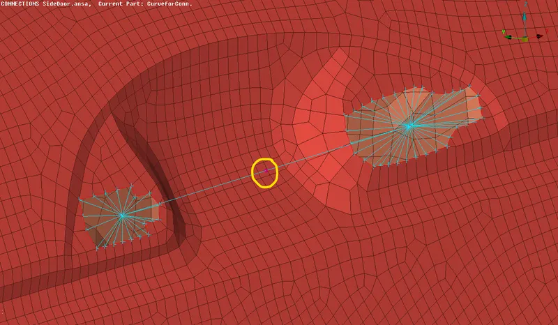
Fig: Concentrated Mass Connection
C-Bush Connection:-
C-bush connection is generally used to connect the door panel to the door glass And generally it represents weather strip which establishes a seal between the car cabin and outside environment. Glass cannot be connected using rigid elements as it is made up of brittle material so it is connected with the help of Bush elements which are having some damping coefficient as well as sufficient rigidity.
To create a c-bush element firstly we have to create spot weld lines around the glass FE and then deploy it as a bush connection using the Feat2Curves option.
After creating the curve we have to copy and offset the curve by some distance and then convert this curve into spot weld lines while making sure that each one of the curve lines is selected and converted separately.
Now to realise these connections, we use connection manager and specify the parts to be connected and some other required data is filled in order to deploy the connection and at last, click on Apply and Realize.
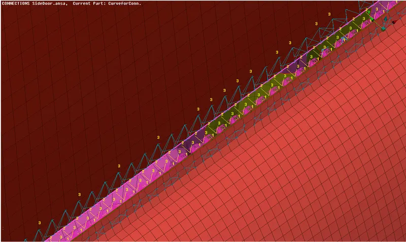
Fig: C-Bush Connection
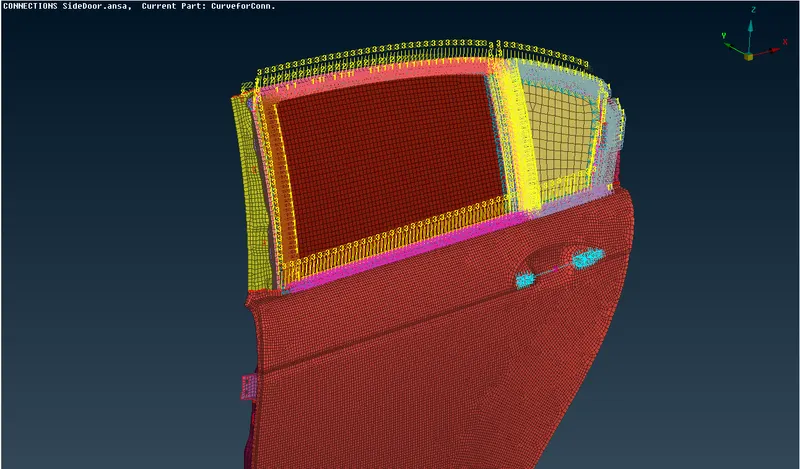
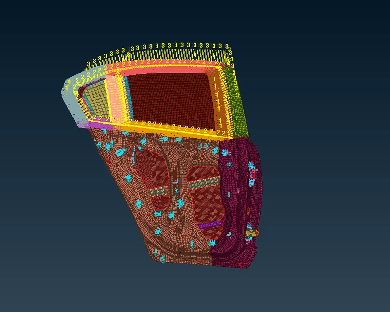
Fig: Rear Door Panel With All Connections Deployed
CONCLUSION:-
Successfully deployed different types of connections for Rear Door.
LEARNING OUTCOMES:-
Learned about assigning PIDs for diiferent parts of the Rear Door.
Learned to deploy different types of connections.