Week 6 - Creating connection for Rear door
CREATING CONNECTION FOR REAR DOOR
AIM:
Now for the given Rear door FE model, Create and Apply different PIDs for different components. Perform suitable connections
OBJECTIVE :
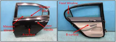
Once we are done with the meshing of the relevant components ,our ultimate aim is to make it for the analysis and find out the results we want to check from it such as whether it is durable,whether it is producing a large amount of penetration and stress and strain while the crash happens etc... Such results we need to find out using our FE model.But the backdoor model of the automobile itself has some sheet metal parts and in addition to it. It also have the trim component which is the plastic part for the providing the power window switches and lock switches etc..And obviously it will be having the main window glass and some cases it will be having a non retractable small fixed glass.This is usually seen with the rear door and some cases even front doors also have the same.Here the model we are given is also having the non retractable glass attached with the main window glass.Now before moving on to the analysis we always make sure that the component is perfectly connected well to each other with the exact connections we use while manufacturing the doors. Every preprocessor have the ability to simulate the real life connections in FE .ANSA have the every connections available in it to help us for making the relevant connections for our FE.This we must make sure because the connectivity between any parts which are not supposed to be unconnected will definitely gives us the incorrect results and if we trust those results and then move on with the physical experimentation for the verification of the results we will end up with big loss and we can see the results from both are not same and have drastic difference in between.Even before running the analysis some solvers have the provision to warn us about the connectivity so CAE engineers will ensure that,But it is the duty of the integration engineer to ensure this connections .
Whenever there is a requirement of deploying the connection in FEA the element type comes into any FEA modeller's mind is 1D elements. We all know well that 1D elements is the one which have one dimension very large compared to the other two dimensionsConnectors are a geometric representation of connections between entities. The advantage of connectors is the ability to create multiple connections at a single time.
In Ansa there are many types of connections according to requirements. In this model we are using some of the connections which are referred below.
- Bolt connection
- Seam weld connection
- Spot Weld connection
- Rigid connection
PROCEDURE:
1. Importing file
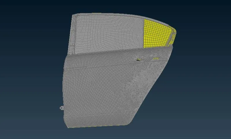
1) Import the model to ANSA, by clicking on File>Open>Browse the file from the list. Click OK
2.Defining part identity
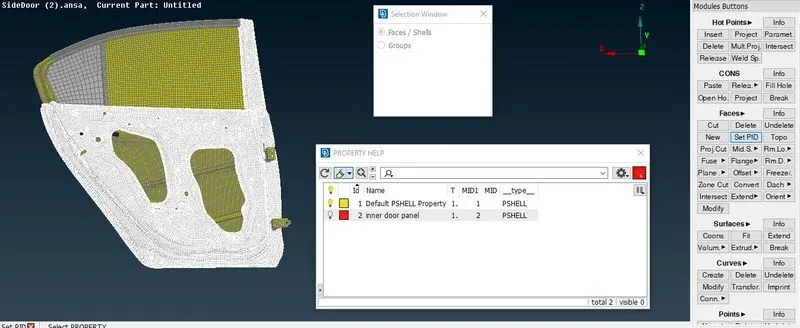
Study the model and understand where and which connections should be given to different parts.We can see that the whole rear door is saved as a single property. So we should separate each part by giving different properties.
Click on set PID in topo>choose Faces/Shell> Select a part> Middle click > In Property Help window right click and create a new property and double click on that property to assign the property to that part.
3. Deploying connection
1. Rigid Body Element (RBE2):
As the name suggests, RBE2 is a type of element which makes connection rigid and prevents movements along translation and rotation in the x, y and z axis. We have two types of RBE2 connections to use i.e. many nodes RBE2 and two node RBE2.
In order to create RBE2 Connection, we have to follow NASTRAN Deck---->ELEMENTs---->RBE2
We will create RBE2 element connection using two methods i.e. Cluster method and 3D bolt point.
This type of connection is created between two or more holes using the same command as mentioned above.
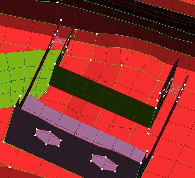
First of all, we have to select slave nodes (nodes which are on the perimeter of holes) slave nodes are dependent nodes. Then by clicking the middle mouse button the master note will select automatically which is the independent node. And then the RBE2 cluster will form. This method is having multiple numbers of dependent nodes and one independent node. After assigning this method, connection will look like as shown in picture below
2. Bolt connection
In order to create Bolt connection between different parts first we need to create 3D points on the COG of the holes using Topo Module > Points > On COG select the inner perimeter of hole
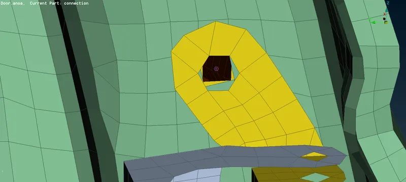
Convert the 3D point created into a Bolt connection using Assembly > convert > select the 3D point > select Bolt connection > ok, 3D point is converted into a Bolt connection.
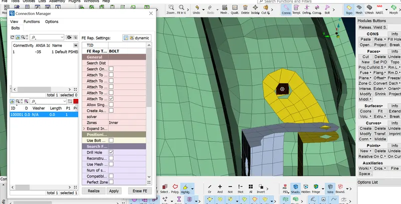
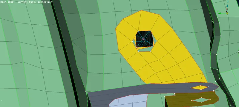
Now we have to Realize the Bolt connection. Goto Assembly > Connection Manager > selection assistant window appears > select the Bolt connection created > Middle click to confirm > Connection Manager window opens.Define the parts to be connected by right-click on P1, P2 > Modify > press F1 on keyboard and select the specific part from GUI.Select the FE representation type as BOLT > Apply > Realize
3.Spot weld connection :
spot welding is a resistance welding process that is used primarily for welding two or more metal sheets together by applying pressure and heat to the weld area.spot weld connections are used in point location and in door assembly there are so many parts where weld spot is needed.
First we have to create a 3D point by TOPO >> POINTS >> ON COG. Then convert the 3D point into spot weld point.
now click on the connection and select the point by middle click connection manager box open. Then adjacent components are selected and given with FE type as RB3-HEXA-RB3. in connection manager.
A PSOLID property is created and property id is entered in that connection manager list and then connection is realized.
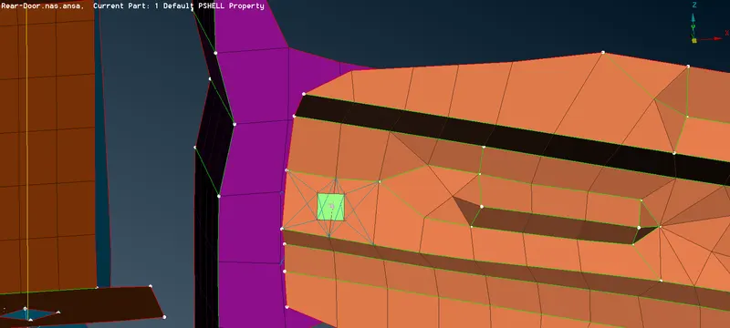
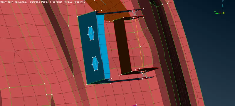
4. Door Hinged connection :
The door hinged connection is created with RBE2 cluster element and in order to movement of rear door towards one direction delete the sixth degree of freedom under NASTRAN >> ELEMENTS >> INFO.
5. Door handle connection :
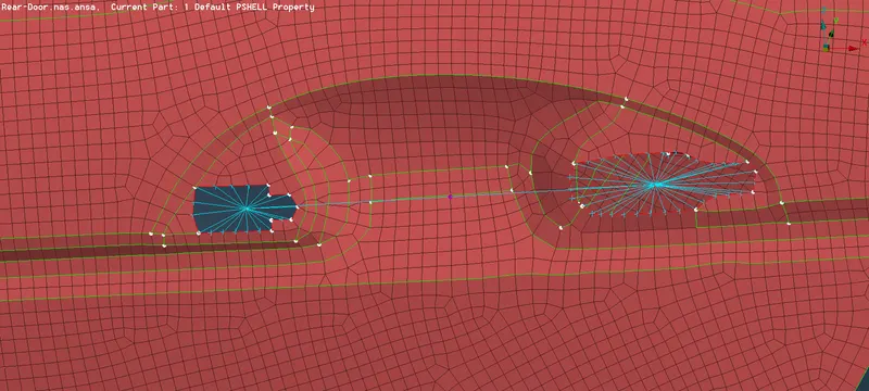
Handle connection is done by using the RBE2 elements along with the CONMI >> CONM2 >> NODES AT COG and apply mass to the centre of RBE2 .Mass is represented in tonnes.
6. Window glass connection :
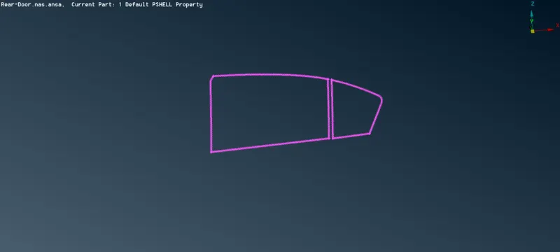
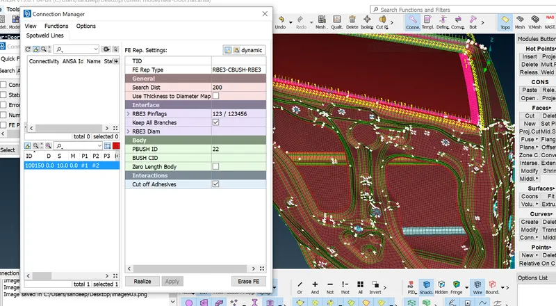
Glass is one which is movable assembly and the connection is done between the glass and weather beads. The connection is created by creating a curve from the FE model by using the option FE2CURVE. Then the curves are converted into a spotline by using the convert option.
then select the connection manager and select the spot line for making connections between glass and weather beads. The FE representative type is RBE3-CBUSH-RBE3 and then realized.
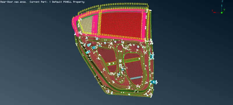
Conclusion :
thus various connections are created and realized using different connection techniques for the rear door FE model using ansa.
Learning outcome :
- how to make Rigid and bolt connection.
- how to make spot weld connection.
- CBUSH element are realized and alligned.
- mass of handle is represented.