Week - 4 - 2D meshing for Plastic components
2D MESHING FOR PLASTIC COMPONENTS
AIM:
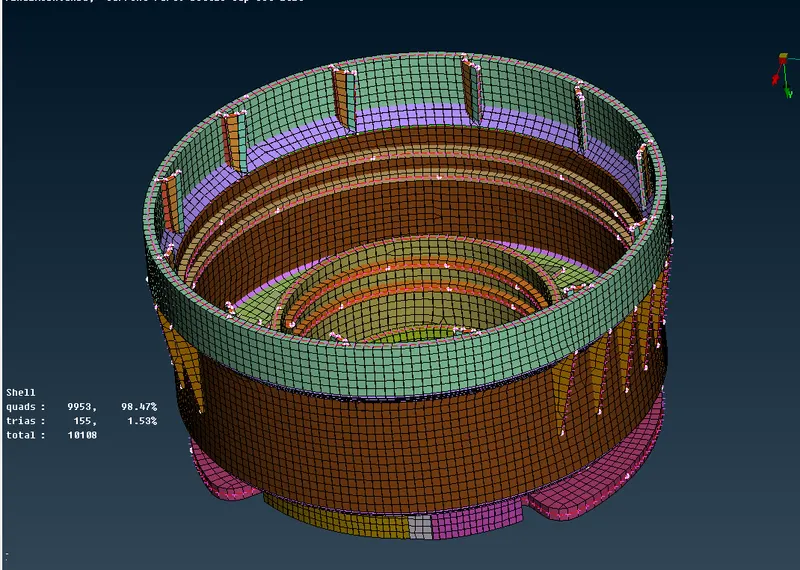
For the given Plastic Bottle Cap model, check for the geometrical errors and take the mid surface by suitable mid surfacing techniques. PID and Thickness assignment has to be done for all the mid surfaces. Mesh the same with given element Quality criteria. (Refer the table Below for the Quality criteria)
QUALITY REQUIREMENT:
|
S.No |
Quality Criteria |
Value |
|
1 |
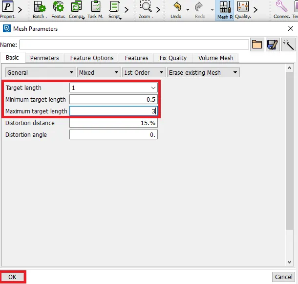
Target/Average length |
1 |
|
2 |
Minimum Length |
0.5 |
|
3 |
Maximum Length |
3 |
|
4 |
Aspect |
3 |
|
5 |
Warpage |
15 |
|
6 |
Skewness |
45 |
|
7 |
Jacobian |
0.7 |
|
8 |
Minimum Quad Angle |
45 |
|
9 |
Maximum Quad Angle |
135 |
|
10 |
Minimum Tria Angle |
30 |
|
11 |
Maximum Tria Angle |
120 |
|
12 |
Tria Percentage |
15 |
PROCEDURE:
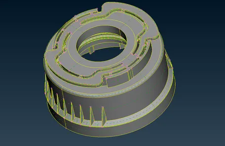
1. Importing CAD Geometry of Bottle Cap in ANSA:
ANSA. File->Open->File Location
2. Checking the geometry:
After importing it, the bottle cap model in the graphical display of the ANSA GUI. By measuring the thickness, the model comprises varying thickness. Which depicts that, the given model is made up of plastic.
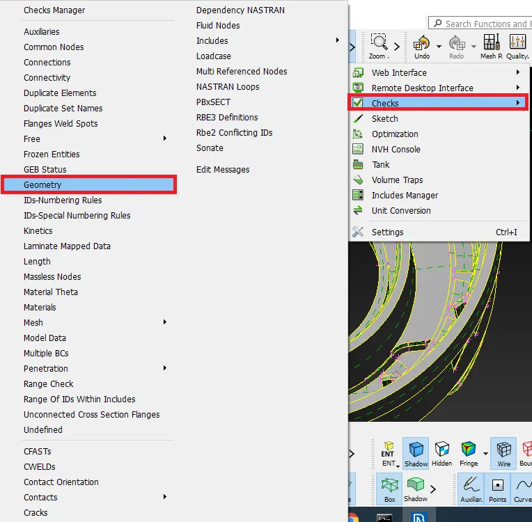
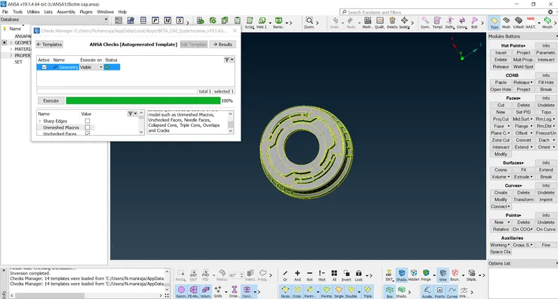
Tools> checks >geometry >all entities >execute.
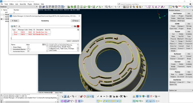
geometry can be fixed using auto or manually
3. MID SURFACE GENERATION
- There are different methods a CAE engineer can use for Mid-Surfacing the component and the best would be Mid-SurfaceModules Buttons in Topo Mode.
- Here I used Offset Mid-surfacing as it's easy and much more efficient for complex surfaces.
- Always enable Cross Hatch while extracting Mid-surface as it helps to select a particular region and space so as to avoid unnecessary errors.
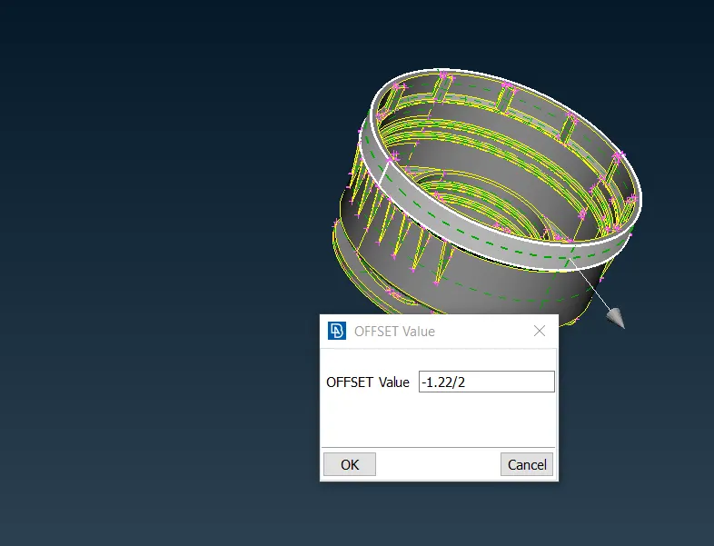
- middle multy is used for some of the feature like rib and fine to extract the mid surface
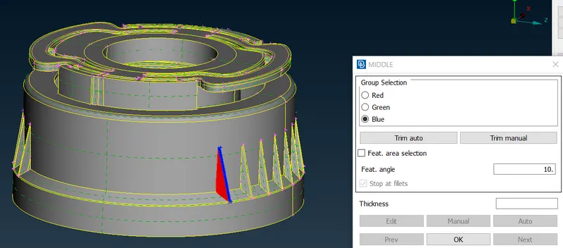
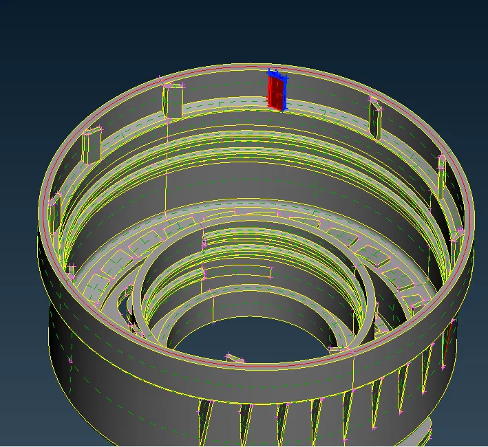 mid surface generation for thread is complicated because it is trapezoidal and element for capturing trapezoidal is tuff but for simplicity we can treat it as rectangular an generate the mid surface using cons2curve option in topo then create new face
 - some feature are repeated like teeth and ribs. midsurfacing of one of these feature is used as reference and copy these using rotate option in transform command is effeiceint way for midsurfacing of identical parts situated in rotating component
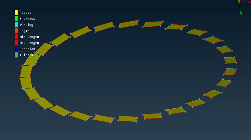
- By using offset and middle multi and rotate option mid surface of the all component can be generated.
- After mid surface generation it is required to check the that all the part is connected properly, if it is not then extend the one of mid surface to the other so that midsurface can capture whole component.
after midsurface generation, it required to check the geometry if there are any type of the error then fix it and check the orientation of the component.
4. ASSIGNING THICKNESS TO THE MODEL
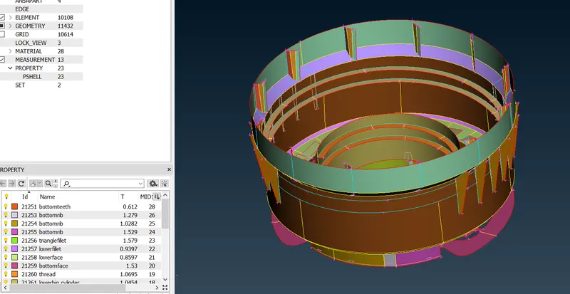
- Assigning the thickness for the different part is important step for the anlaysis for assigning the thickness topo⇀face⇀set pid⇀click⇀select face⇀middle mouse⇀right click⇀new ⇀pshell⇀rename⇀apply thickness⇀ok
5.MESHING OF COMPONENT
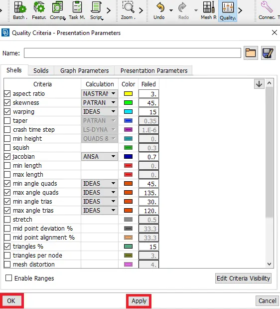
- Before meshing it is required to apply the mesh parameter and quality criteria as per given condition
- mesh panel go to perimeter⇀length⇀select the geometry for perimeter and give the length as same size as element target length.
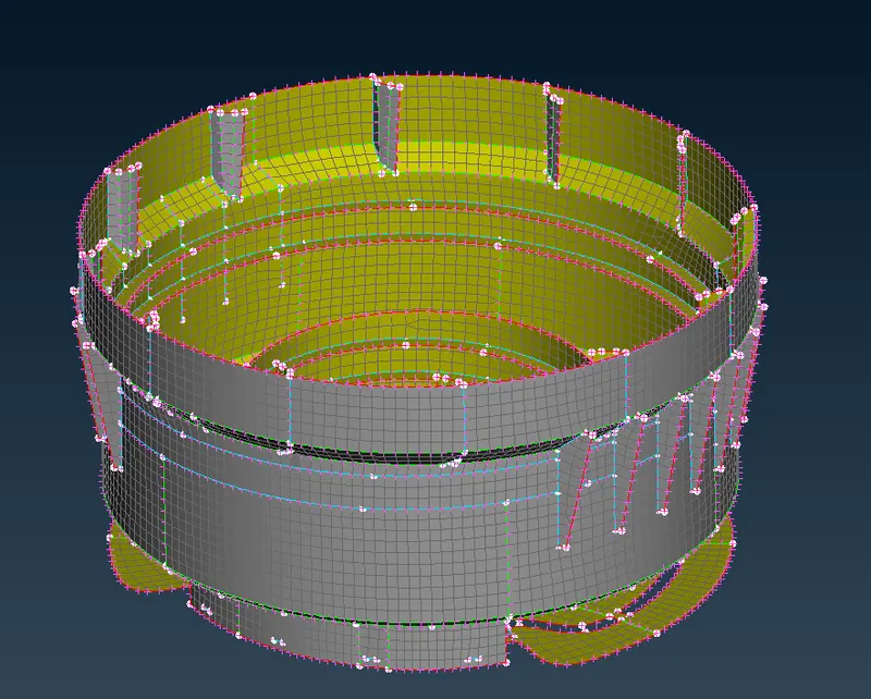
- For meshing go to the mesh module⇀mesh generation⇀best⇀click the surface were we want to mesh and middle click on the mouse
- always reconstruct the mesh once the mesh is done for reconstruct go to the mesh module⇀shell mesh⇀reconstruct⇀click the surface we want to reconstruct.
6. CONCLUSION
i have successfully meshed the plastic model. correct midsurface generation of plastic is really important otherwise there are lot of chances of error in analysis.
7. OUTCOMES
- Learn about to the taking midsurf surface to the plastic component.
- Perform the toplogy cleanup and fixing those parametrs on the given cap model.
- Usage of transform option(rotation), where to save time.
- setup the quality and clearing those errors
- Assigning the thickness.