Week 6 - Creating connection for Rear door
AIM
>> For the given FE model of a car rear door, assign different PID for different regions and make suitable connections wherever required.
Procedure
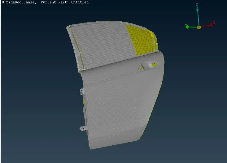
>> The given FE model is imported into ANSA software by clicking on the File>Open function. The imported FE is shown below.
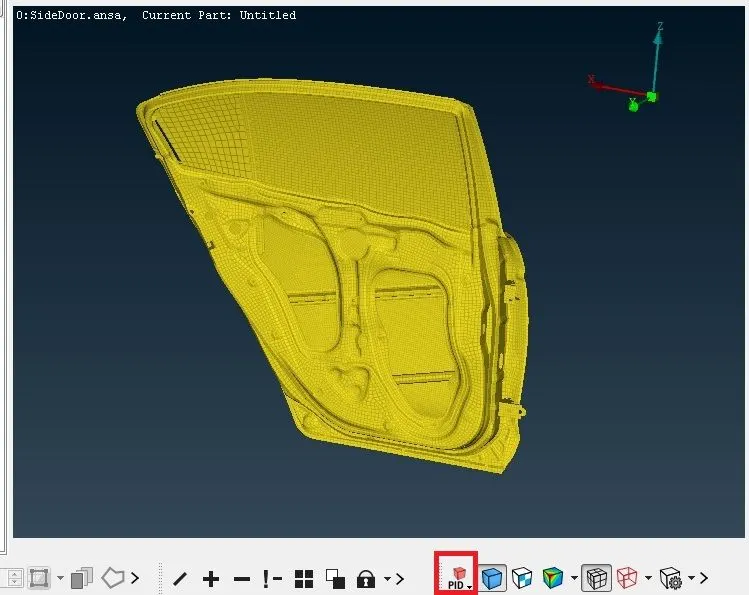
>> On Switching to PID View mode it is seen that all the regions are of same colour which means they are included in the same PID as seen below.
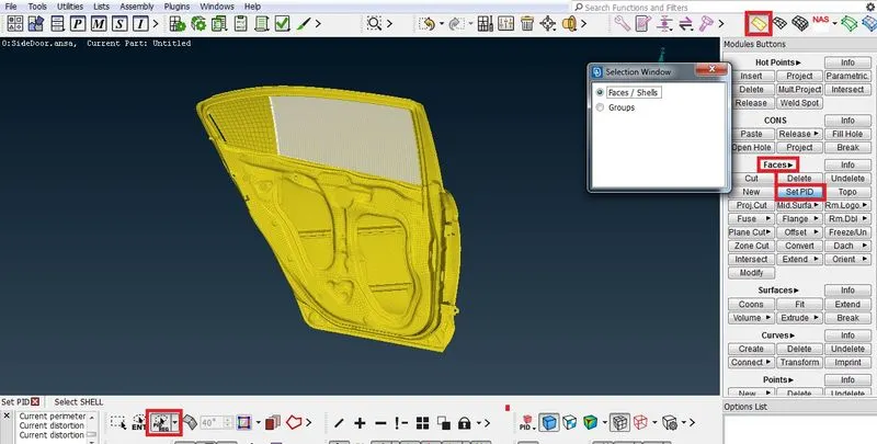
>> To ensure proper connection between various parts, various regions are to be sorted into different PID's. This is done be executing 'Topo Module>Faces>Set PID' function and changing selection mode to PID region and then selecting the required elements and creating new PID's for every sorted region. It is shown in the below picture.
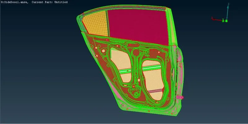
>> This process is repeated until all the different regions are sorted into individual PID's. The FE model after assigning adequate PID's is shown below.
>> Rigid connections-RBE2-multinode >This connection is enabled by swithcing to the Solver module Deck and selecting NASTRAN solver. Then the RBE2 function under the elements area is selected as shown below. The nodes selection loop function is enabled for quicker selection of nodes.
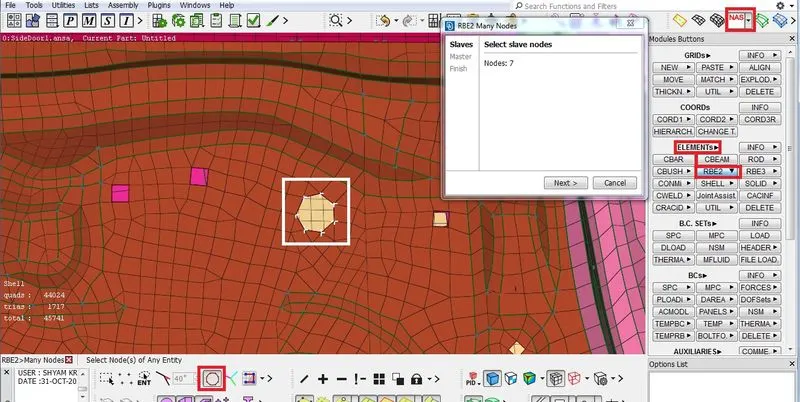
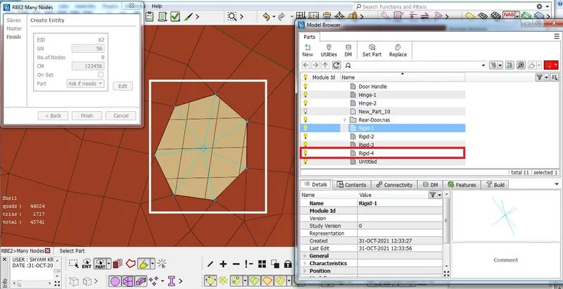
>> The slave nodes(dependent) are selected and the master node(independent) is automatically assigned to the centroid of the slave nodes. The new connection is sorted into a new part as shown below.
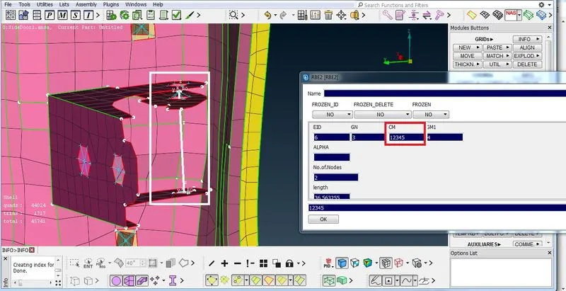
>> In the Hinge region, two node RBE2 connction is used to model the central hinge and the rotational motion along z axis is unconstrained by removing the 6th number from the degrees of freedom.
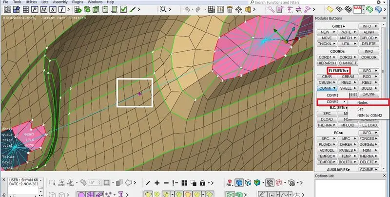
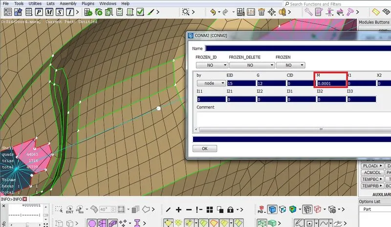
>> The door handle is assigned a mass at the mid point as shown in the below picture by executing the Elements>CONMi>CONM2 function under the NASTRAN solver deck module as shown below. The mass value is entered in tonnes.
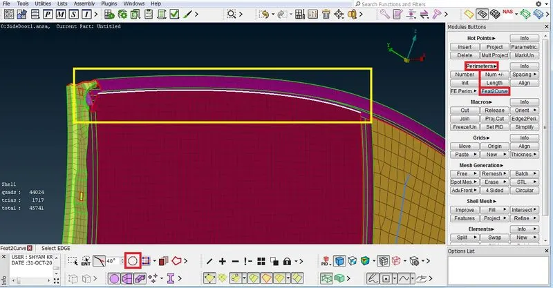
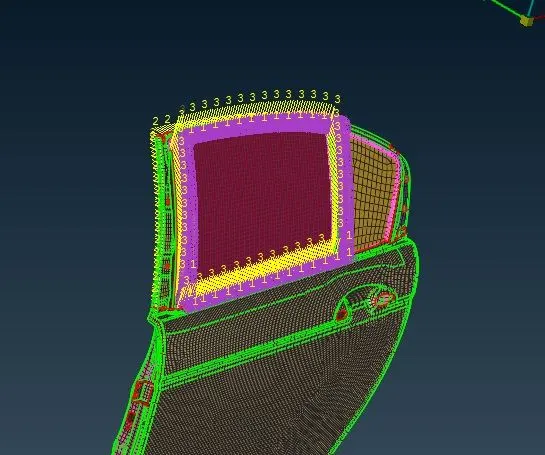
>> The window glass is connected with the frame using RBE3-CBUSH-RBE3 element by first creating a curve from the FE perimeter using the Feat2Curve function under the perimeters area in the Mesh module as shown below.
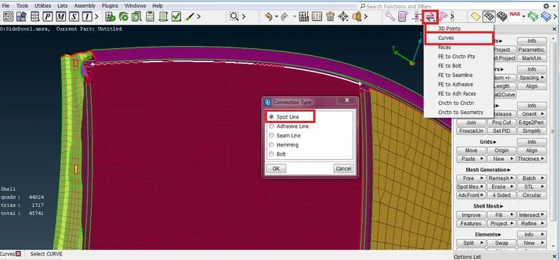
>> This curve is then converted using the convert function in the assembly tool bar and selecting spot line option.
>> Now the spot line is accessed by connection manager and the PID regions to be connected are selected as P1 and P2. The element type is selected as RBE3-CBUSH-RBE3.
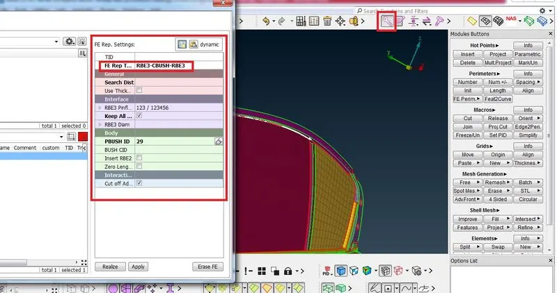
>> After the connectivity is established all the CBUSH elements are oriented to coordintates with a default value of 0(C1), which aligns all the CBUSH axis along the global coordinate direction. The realized RBE3-CBUSH-RBE3 connection is shown below.
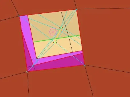
>> A bolt connection is formed by creating a 3d point and converting the 3d point to bolt using the connection manager in the assembly tool bar. The realized bolt connection is shown below.
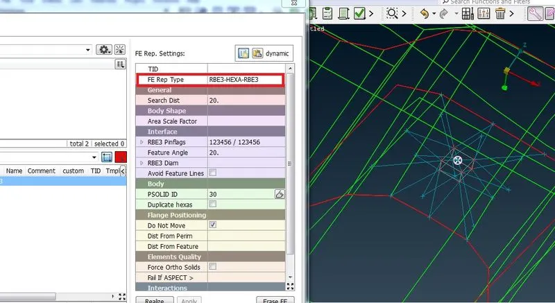
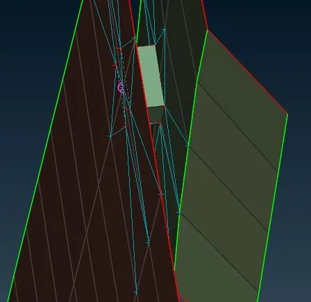
>> Similarly spot weld connections are formed by converting a 3d point to a spotweld and assigning the FE rep type as RBE3-HEXA-RBE3 as shown below. The realized spot weld is also shown.
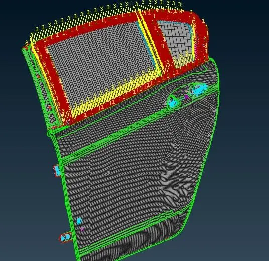
>> The final condition of the Connected Rear door FE is shown below.
Learning Outcomes
>> Knowledge about various type of elements used for connection between various parts of door such as RBE2, RBE3, Bolt and spot weld were acquired.
>> Understood how to deploy Zone cut when CAD data is not available.
>> Deployed and realized various type of connections using appropriate FE representative elements such as RBE3-HEXA-RBE3 for spot weld, RBE3-CBUSH-RBE3 for weather strips, RBE2 for rigids.
Conclusion
>> The Rear door FE was interconnected with appropriate connections successfully using ANSA software interface.