Week - 4 - 2D meshing for Plastic components
AIM
To mesh the given Plastic Bottle Cap with the specified meshing quality criteria given below:
|
S.No |
Quality Criteria |
Value |
|
1 |
Target/Average length |
1 |
|
2 |
Minimum Length |
0.5 |
|
3 |
Maximum Length |
3 |
|
4 |
Aspect |
3 |
|
5 |
Warpage |
15 |
|
6 |
Skewness |
45 |
|
7 |
Jacobian |
0.7 |
|
8 |
Minimum Quad Angle |
45 |
|
9 |
Maximum Quad Angle |
135 |
|
10 |
Minimum Tria Angle |
30 |
|
11 |
Maximum Tria Angle |
120 |
|
10 |
Tria Percentage |
15 |
Procedure
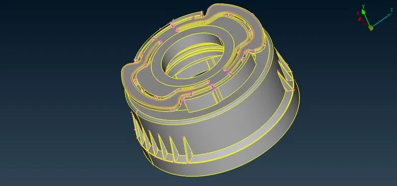
>> The given parent geometry file 'Bottle cap.ansa' is imported into ANSA by clicking on File>Open. The imported geometry is shown below
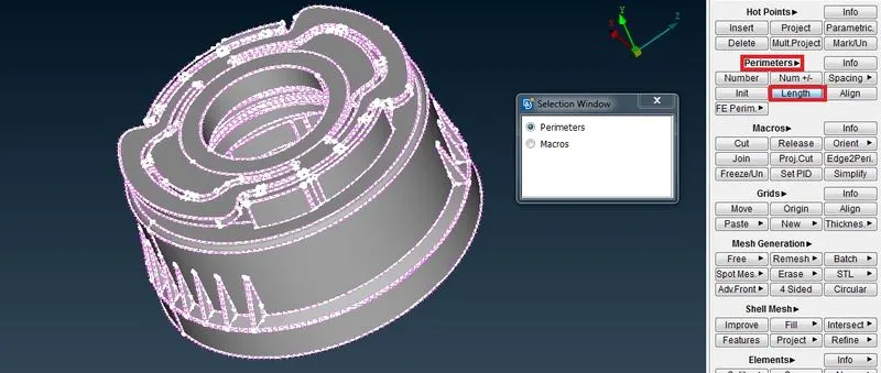
>>The mesh module of ANSA is selected and then Length function under perimeter is exectuted to set the perimeters and macro length to 1 mm as shown below.
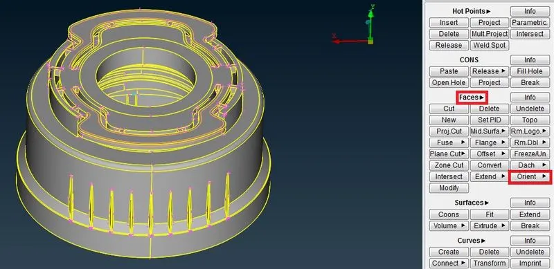
>> 'Topo' function is executed by clicking on the TOPO module>Faces>Topo and selecting the CONS(curves on surfaces) on the CAD geometry to create topological conditions between adjacent CONS.
>> 'Orient' function is executed to create uniform orientation to all visible faces of the Parent geometry by clicking on the TOPO module>Faces>Orient and selecting the required surfaces. Uniform orientation is indicated by same colour of the oriented faces.
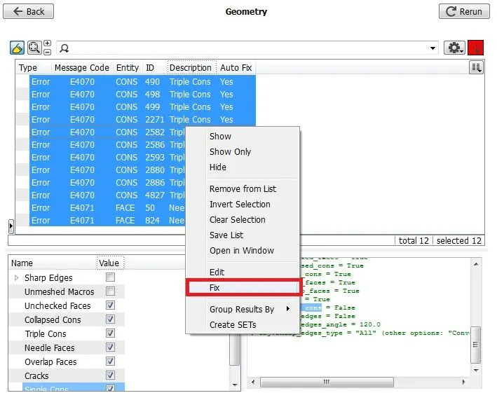
>> Geometry checks is done by executing the Geometry function under Menubar>Tools>Checks. When execute button is clicked the errors are shown as below
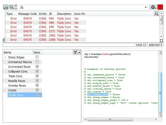
>>These errors are fixed by selecting all those errors and selecting 'Fix' option as shown below. ANSA automatically fixes those errors. Incase if there is no automatic fix, the surface need to be checked. In some cases triple cone shows as error but there might be a three surface junction resulting in the triple cone. So it is not an error. In other cases manual repair of the surface is done using various surface editing tools in ANSA.
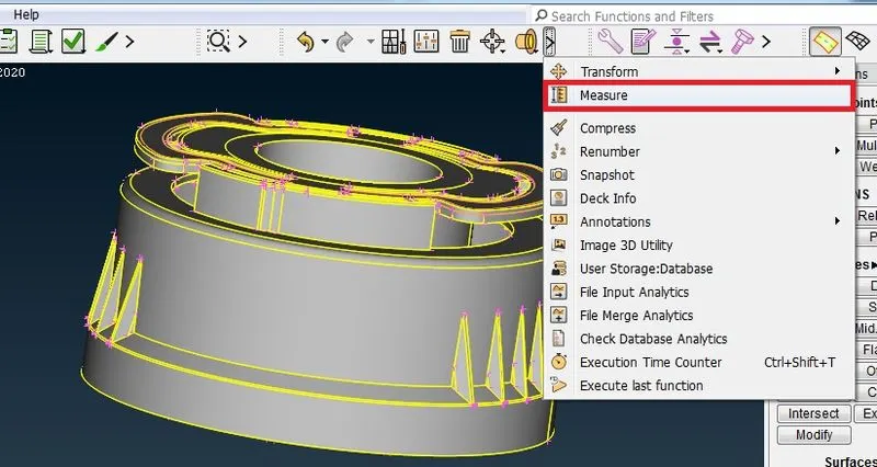
>> As this is a plastic component, the thickness is not uniform. so the thickness is measured at various places using the measure tool in Utilities>Measure and then selecting Nodes/Edges as shown below.
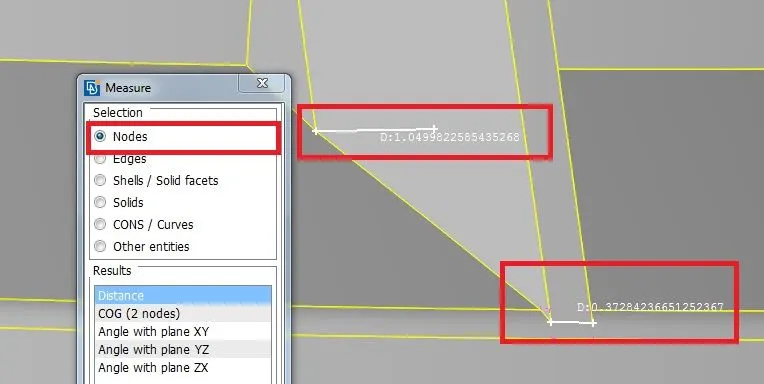
>>After measuring the thickness, the midsurface is extracted by using the middle and offset functions under the Faces section of the Topo module.
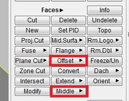
>>This process is repeated again and again until each part of the parent geometry is converted into a shell surface. For each surface with varying thickness a different PID is assigned and the measured thickness obtained from parent geometry is provided as the thickness input.
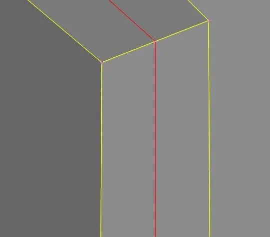
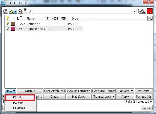
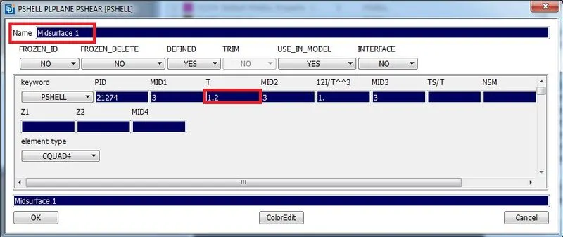
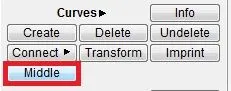
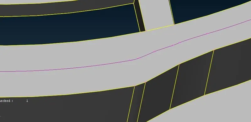
>> To take midsurface of surfaces with varying thickness, a middle curve is generated by executing the function 'Middle' under the curves group within the Topo Module. The generated middle curve is then converted into midsurface by using the various surface generation commands such as revolve and sweep under the Surfaces group within the Topo Module as shown below.
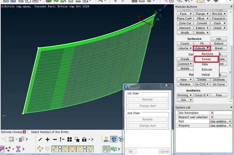
>> The midsurface generation process through sweep function under the Surfaces group of Topo module is shown below:
>>After extracting the mid surface, the mid surface is checked for geometric problems using the checks manager
>> Align holes if any with Mesh Module>Perimeter>Slide to make them parallel to closest perimeter.
>> To achieve a good quality mesh, holes should be captured by even number of edges. If not, check them with Mesh Module>perimeter>Number and change with Mesh Module>perimeter>Numb+/-.
>> Check geometry for areas which has lesser length than minimum element length. Then change perimeter length of that place to required target element length.
>> Change perimeter/Macros length to the target mesh element length provided by clicking on Mesh Module>Perimeters>Length>Perimeters/Macros and the select the macro area or perimeter whose element length is to be changed.
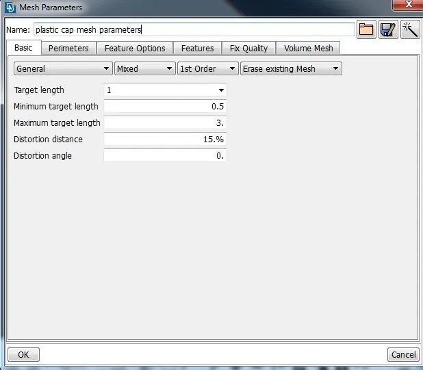
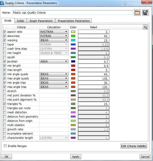
>> The meshing parameters and the quality criterira are entered as required in the question as shown below. Both these parameters are accessed from Menubar>Utilities.
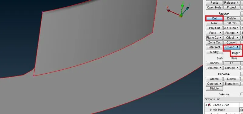
>> The midsurfaces extracted one by one are joined with each other using the extend and intersect functions under the Faces group in the Topo Module.
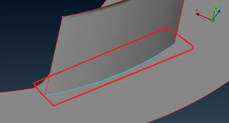
>>Successful extension of the edge is indicated by a triple cone of cyan colour as shown below.
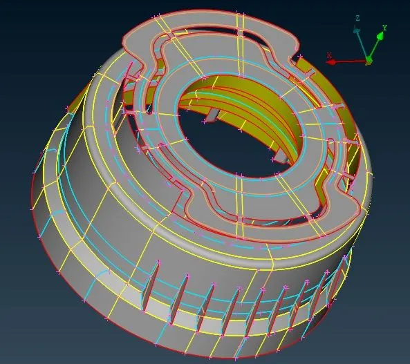
>>The extracted midsurface after interconnecting the faces together and re arranging the edges so as to obtain a proper mesh flow is shown below.
>> The component is now meshed as per the required quality parameters by switching to the Mesh module and then selecting 'Best' meshing algorithm under 'Mesh generation'. The resulting mesh is again corrected if required by using 'Reconstruct' function under 'shell mesh'. The 'smooth' function is used to obtain smooth mesh lines alignment after obtaining required mesh.
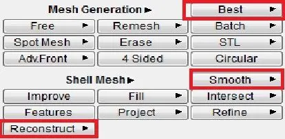
>> In meshing back to back trias, trias near edges, fillets, circular openings and tria concentration are avoided using various tools such as 'Swap', 'Split' and 'Join' functions under 'Elements' in Mesh module. Also the paste function under the 'Grids' is also used to combine adjacent nodes to move the trias away from each other.
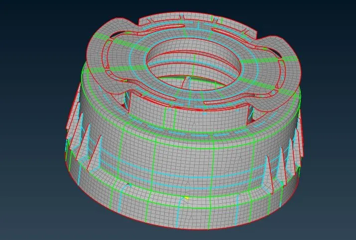
>> The final mesh obtained is shown below.There are some failed elements near to Triple CONS or at smaller regions which are bounded by two Triple CONS. Those OFF elements are kept as it is if not possible to solve them.
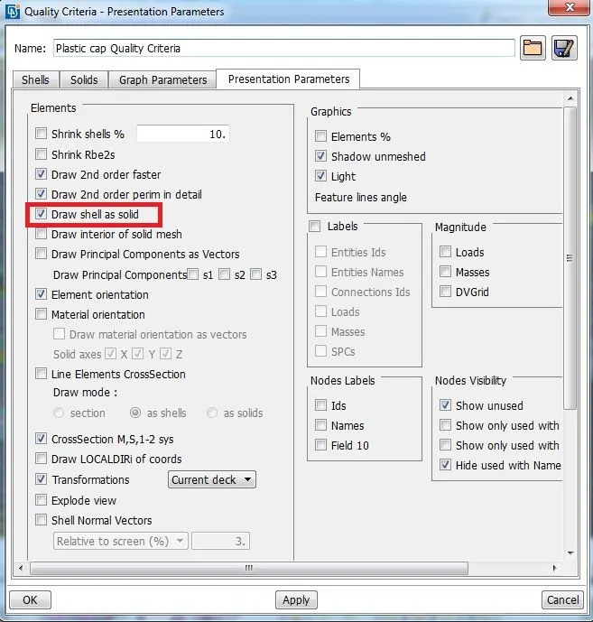
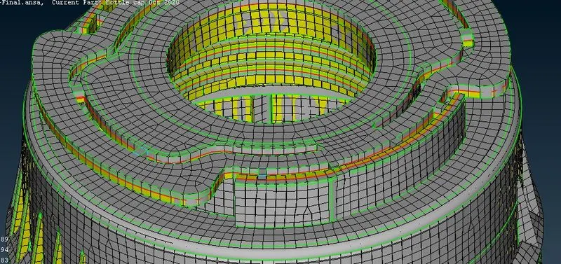
>>Under the presentation parameters under the Quality criteria, draw shell as solid option is enabled to visualize the elements created with the thickness assigned to them. The parent geometry is also visualized along with this to verify whether the meshed elements are following the edges of the CONS. The output is shown below.
Learning Outcomes
>>The Various tools used for midsurface extraction of surfaces with varying thickness was made familiar.
>>Different methods of surface generation with the help of generated Curves was practised.
>>Various problems occuring during meshing of 2d Plastic component was identified and its trouble shooting skill was acquired.
Conclusion
>>The 2D meshing process of the Plastic Bottle Cap was completed using the required meshing parameters and quality criteria given in the question and a final mesh with smooth mesh flow was obtained.