Week 3 - 2D meshing for sheet metal
Aim
To mesh the given hood geometry as per the below quality Criteria:
|
S.No |
Quality Criteria |
Value |
|
1 |
Target/Average length |
5 |
|
2 |
Minimum Length |
2 |
|
3 |
Maximum Length |
7 |
|
4 |
Aspect |
3 |
|
5 |
Warpage |
15 |
|
6 |
Skewness |
45 |
|
7 |
Jacobian |
0.7 |
|
8 |
Minimum Quad Angle |
45 |
|
9 |
Maximum Quad Angle |
135 |
|
10 |
Minimum Tria Angle |
30 |
|
11 |
Maximum Tria Angle |
120 |
|
10 |
Tria Percentage |
15 |
Procedure
>> The given hood geometry file 'Hood model_1.stp' is imported into ANSA by clicking on File>Open. The imported geometry is shown below
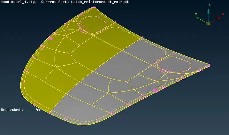
>> 'Topo' function is executed by clicking on the TOPO module>Faces>Topo and selecting the CONS(curves on surfaces) on the CAD geometry to create topological conditions between adjacent CONS.
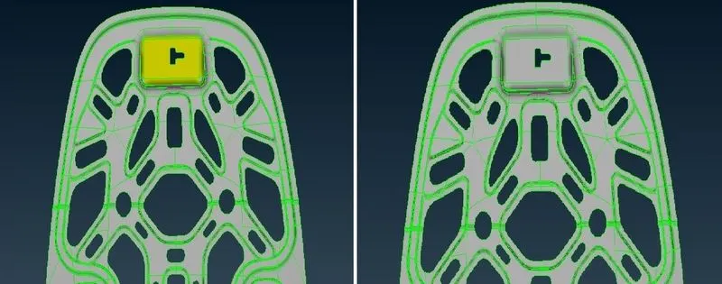
>> 'Orient' function is executed to create uniform orientation to all visible faces of the CAD geometry by clicking on the TOPO module>Faces>Orient and selecting the required surfaces. Uniform orientation is indicated by same colour of the oriented faces. The changes after orientation are shown in the images shown below.
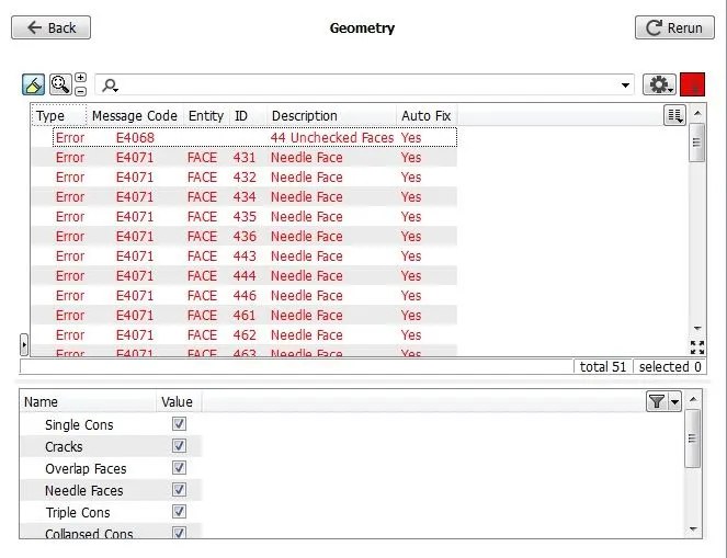
>> Geometry checks is done by executing the Geometry function under Menubar>Tools>Checks. When execute button is clicked the errors are shown as below
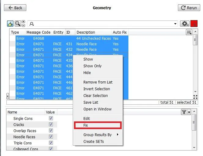
>>These errors are fixed by selecting all those errors and selecting 'Fix' option as shown below. ANSA automatically fixes those errors. Incase if there is no automatic fix, the surface need to be checked and a manual repair of the surface is done using various surface editing tools in ANSA.
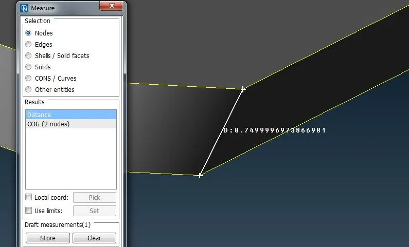
>> The thickness of the component is measured using the measure tool in Utilities>Measure and then selecting Nodes/Edges as shown below.
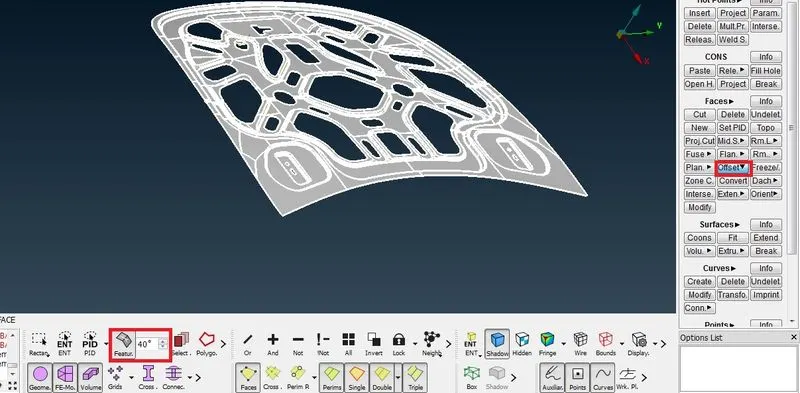
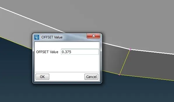
>>As this is a sheet metal component, the thickness will be uniform throughout. After measuring the thickness, to extract the midsurface an offset of one of the surfaces is made to half of the measured thickness using the offset function in TOPO module>Faces as shown below. To make the selection process easy, the Feature Area function is selected from MENUBAR>Feature Selection and then ANSA selects only those neighbouring areas, whose angles formed by normals of those areas is less than the specified
'feature angle'.
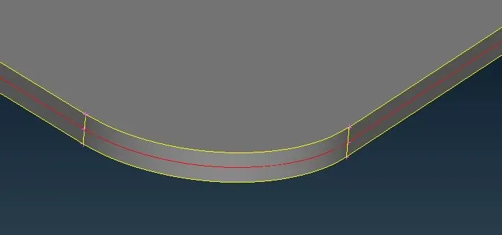
>>The extracted Mid surface will be shown as a red coloured edge exactly in the middle along the thickness of the original geometry as shown below.
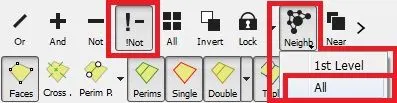
>>The !Not and Neighb [All] functions are used to make only the extracted mid surface visible and all the rest of geometry hidden.
>>After extracting the mid surface, the mid surface is checked for geometric problems using the checks manager
>> Align holes with Mesh Module>Perimeter>Slide to make them parallel to closest perimeter.
>> To achieve a good quality mesh, holes should be captured by even number of edges. If not, check them with Mesh Module>perimeter>Number and change with Mesh Module>perimeter>Numb+/-.
>> Check geometry for areas which has lesser length than minimum element length. Then delete hot
points there and change perimeter length of that place to required target element length.
>> Change perimeter/Macros length to the target mesh element length provided by clicking on Mesh Module>Perimeters>Length>Perimeters/Macros and the select the macro area or perimeter whose element length is to be changed.
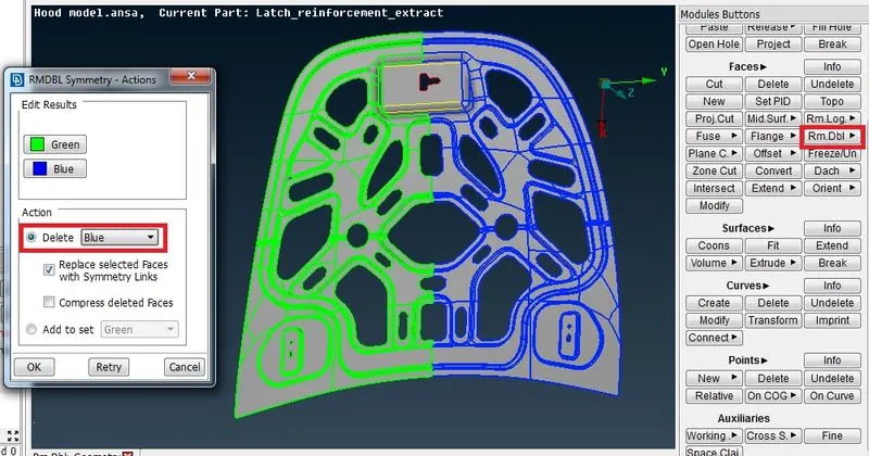
>>To reduce the amount of time required for meshing process, the symmetrical faces found out and one of the symmetrical faces are replaced with 'symmetrical links' using the 'Rm.Dbl [Geometry]' function as shown below. The symmetrical faces are highlighted in blue and green colour as shown below.
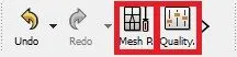
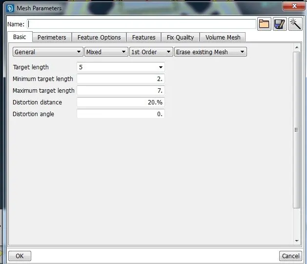
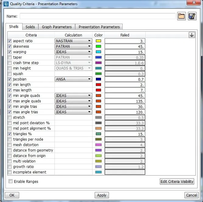
>>Now whatever action is done in one of the faces is automatically created in its symmetrical link created above.After removing one of the symmetrical faces, the quality criteria and the meshing parameters are entered as required in the question as shown below. Both these parameters are accessed from Menubar>Utilities.
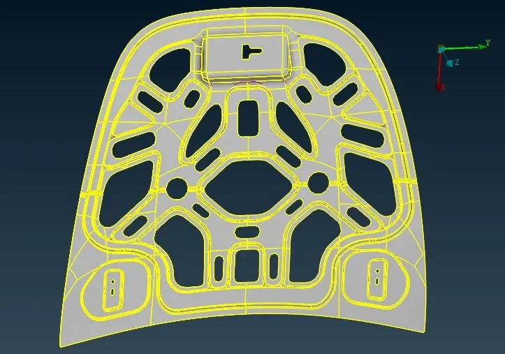
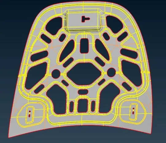
>> Geometry clean up is done in which the CONS are re arranged so that the minimum gap between CONS do not fall below the minimum element length while meshing. The inner panel before and after geometry clean up is shown below.
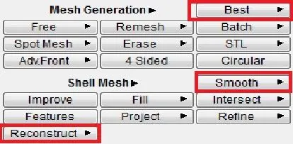
>>The component is now meshed as per the required quality parameters by switching to the Mesh module and then selecting 'Best' meshing algorithm under 'Mesh generation'. The resulting mesh is again corrected if required by using 'Reconstruct' function under 'shell mesh'. The 'smooth' function is used to obtain smooth mesh lines alignment after obtaining required mesh.
>>In meshing back to back trias, trias near edges, fillets, circular openings and tria concentration are avoided using various tools such as 'Swap', 'Split' and 'Join' functions under 'Elements' in Mesh module. Also the paste function under the 'Grids' is also used to combine adjacent nodes to move the trias away from each other.
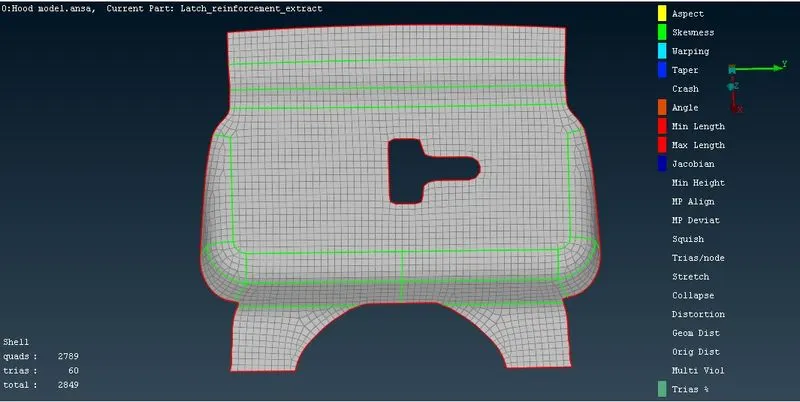
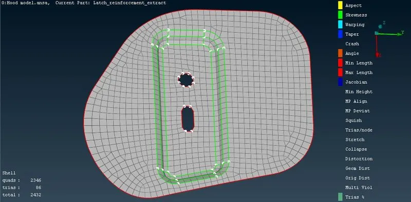
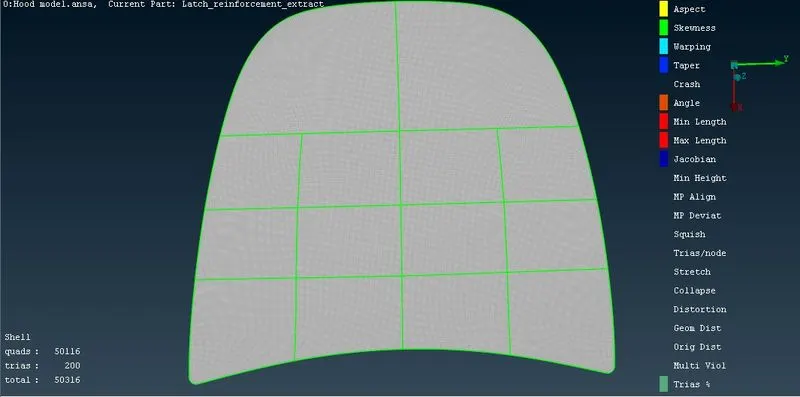
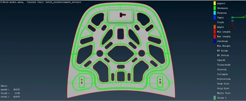
>>The final mesh obtained for various components of the hood geometry satisfying all the quality criteria are shown below.
Learning Outcomes
>>The interface and various functions related to meshing and geometry clean up in ANSA software was made familiar.
>>Knowledge of Mid surface extraction of 2d sheet metal component and its geometry clean up using ANSA software was acquired.
>>Meshing process of 2d sheet metal component using ANSA software was understood.
>>Various problems occuring during meshing of 2d sheet metal component was identified and its trouble shooting skill was acquired.
Conclusion
>>The meshing process of the hood component was completed using the required meshing parameters and quality criteria given in the question and a final mesh satisfying all the quality parameters and smooth mesh flow was obtained.