Week 6: Conjugate Heat Transfer Simulation
AIM: Run a Simulation on Conjugate Heat Transfer at a Cylindrical Pipe
INTRODUCTION: In a simple world, you could simulate fluid flow and assume that the walls of the container were at a constant temperature or even adiabatic.
2> In reality, however, the heat transfer between solids and surrounding fluids couples the temperature field in both materials, and thus CFD software must be able to account for this phenomenon.
3> CONVERGE features a state-of-the-art conjugate heat transfer (CHT) model for simultaneously predicting heat transfer in both the fluid and solid portions of the domain, which is critical for many applications.
THEORY: Since in the Conjugative Heat Transfer there are many Types of Simulation but here we will only explain the IC Engine CHT.
Internal Combustion Engines
a> The internal combustion engine industry is moving toward simulating the entire system rather than independent components.
b> The accuracy of the predicted combustion in the cylinder is dependent on the temperature boundary conditions in the cylinder. By considering heat transfer in the metal components (e.g., the cylinder head, liner, piston, etc.), the cylinder wall no longer has a user-specified temperature, but instead has temperatures predicted as part of the complete-system simulation
c> This makes the overall simulation results more predictive by reducing the dependence on assumed boundary conditions.
EXPERIMENT:
1> BASE CASE SETUP
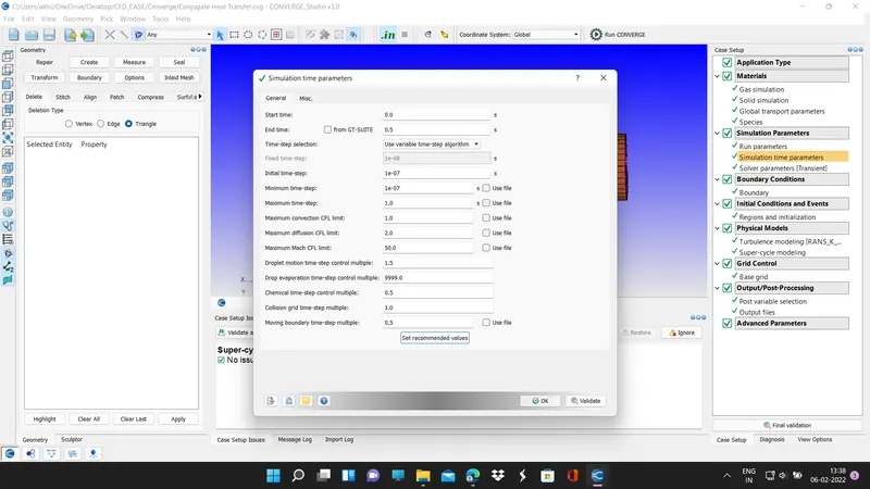
SIMULATION TIME PARAMETER
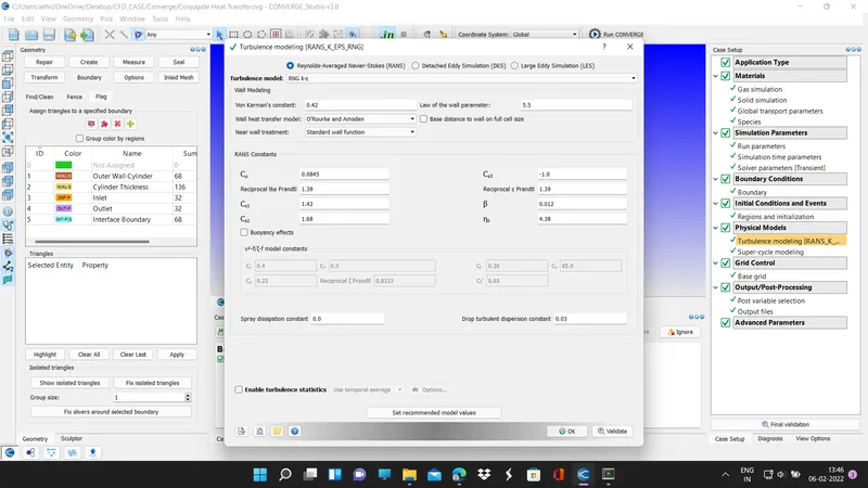
TURBULENCE MODELLING
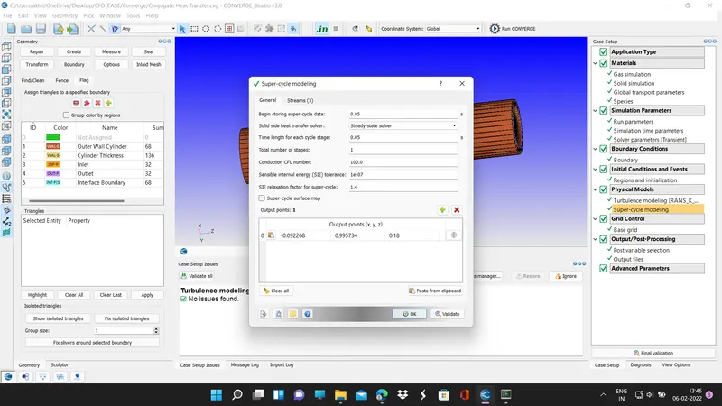
SUPER CYCLING ENTRIES
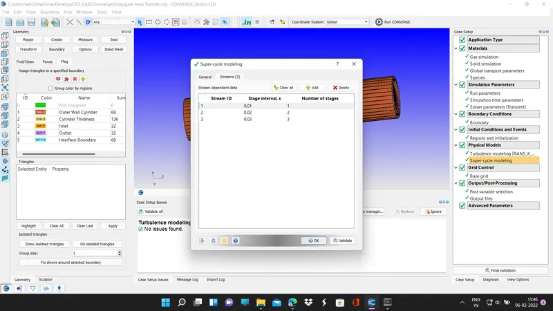
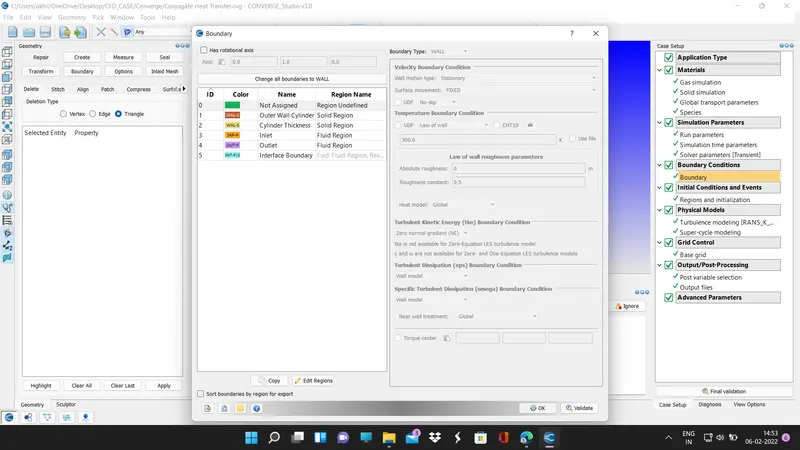
BOUNDARY CONDITION
2> BASE GRID
dx=0.004,dy=0.004,dz=0.004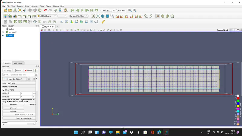
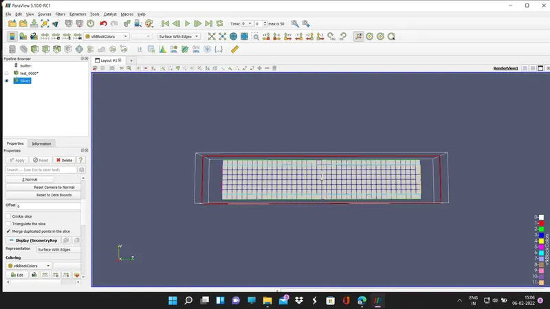
dy=.0.005, dy=0.005,dz=0.005
dz=0.006,dy=.0.006,dz=0.006;
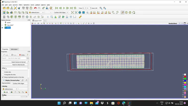
3> COMMON FOR ALL GRID CELL GRAPH WITH HAVING A MINOR DIFFERENCE
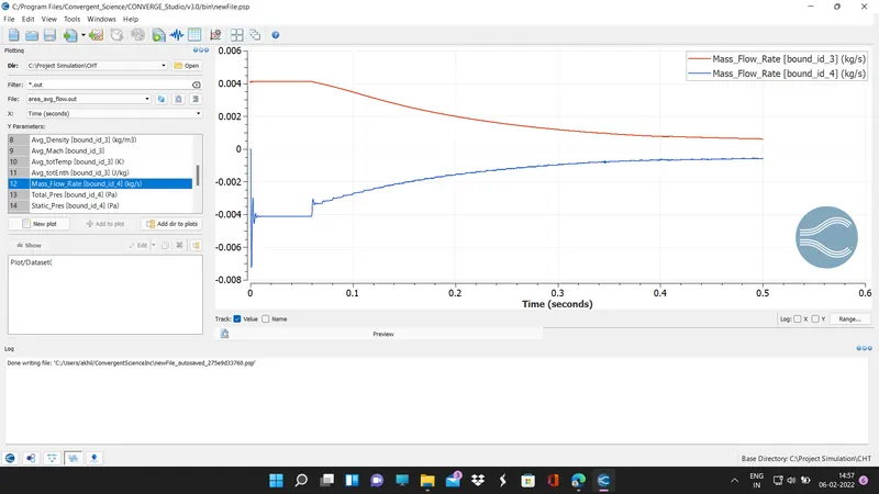
3.1> Mass Flow Rate
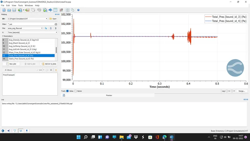
3.2> Total Pressure(totally Overlap with Each other)
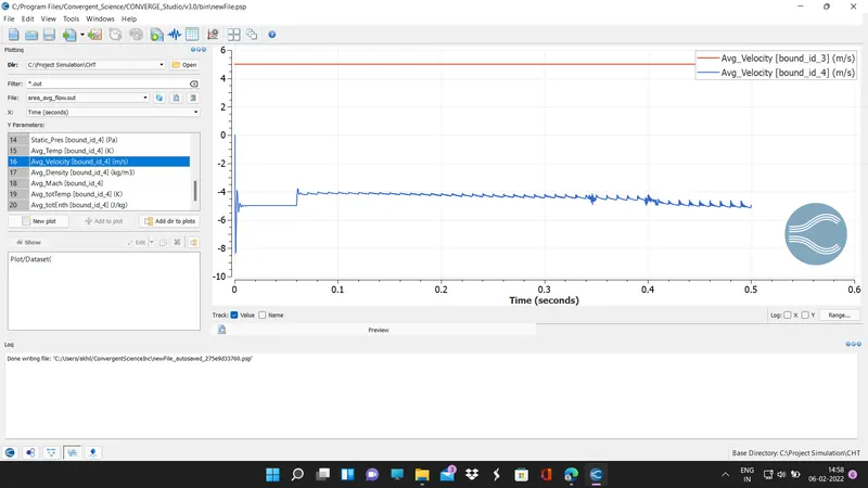
3.3> Average Velocity
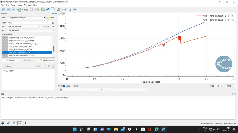
3.4> Average Temperature
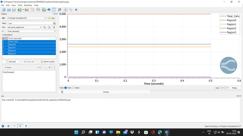
3.5> Regional Cell
4> Reference Link
4.1> Youtube Link
4.2> Files Link
https://drive.google.com/drive/folders/1PlQ26ZL43EHBN6XEkKqRT9vFumjYEy9q?usp=sharing