Week 6:- Clamp Unit & Pin-Clamp Unit Design Challenge
OBJECTIVE:
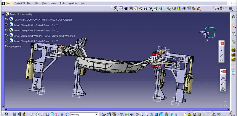
To design 3 different types of swivel clap uit with different riser, blade, and clamp arm for the givn car panel and to design a pin clamp unit for the given car panel.
SOFTWARE USED:
CATIA V5
Two types of clamp units used to clamp the car panel. They are
- Power clamp unit.
- Swivel clamp unit.
To weld these parts, they must be fixed using 3-2-1 principle:
3-2-1 PRINCIPLE.
Fixture must correctly locate a workpiece in a given orientation with respect to a cutting tool or measuring device, or with respect to another component. locating and clamping are the critical functions of any work holding fixture.
A workpiece free in space can move in an infinite number of directors. for analysis, this mtion can be broken down into 12 directional movements or "degrees of freedom". All twelve degrees of freedom must be restricted to ensure proper referencing of workpiece.
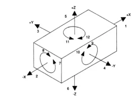
fig- The twelve degrees of freedom
The best and most effective method of part location is referred to as the 3-2-1 method.
6 translational degrees of freedom: +x,-x,+y,-y,+z,-z
6 rotational degrees of freedom.
1. C-ROT around X-axis
2. AC-ROT around X-axis
3. C-ROT around Y-axis
4. AC-ROT around Y-axis
5. C-ROT around Z-axis
6. AC-ROT around Z-axis
If we fix the clamp as per the 12 degrees of freedom listed above, then we can arrest the panel in a fixed position.
6- degrees of freedom are restricted by 2-pin units.
6- degrees of freedom restricted by 3-clamp unit and rest units.
CLAMP UNIT
Clamp unit is the unit designed to hold/clamp the car panel with NC blocks/mylars/rest by using a pneumatic clamp cyinders.
PARTS OF CLAMP UNIT:
1.Mylar/NC block/Finger: Fingers is a movable part which is used to hold the car part from top against backup and they are usually mounted on the clamp arm.
2.L-block: L- shaped blocks are used to ount the finger to clamp arm, besides allowing adjustents for locator pin in two directions.
3.Shim/Spacer: They allow the finger to be moved to the correct xyz locating and allow the customer to make adjustment to improve quality of their product.
4.Blade:Part into which the aforeside element are attached to
5.Riser- L-shaped or T-shaped tall block which reularly patterned holes to attach the above mentioned parts in modular way blade space. Riser is eiether a maked part or standard part.
6.Stopper: The function of stopper is to restrict clamp going beyond the limit. stopper is mounted between clamp arm and rest/blade. stopper has two parts male and female, when these two parts meets they restrict motion.
CONSIDERATION WHILE DESIGNING CLAMP UNIT:
1.STUDY OF PROCESS PLANNING DOCUMENT:
Process planning document is the document which contain the data and other information related to the design clamp unit.
process document should contain following information which are necessaary to design clamp unit.
- No. of sheet metal panels to be welded.
In this project there are 5 sheet metal parts needed to be joined & welded together.
- Total no. of spots.
- Weld gun details if it is already reccomended by process engineer study it in detail like shape & its type.
- Study the PLP(principle locating points) data along with the nearby spot data.
2. HEIGHT SELECTION
Take an overview of working height if you are having manaul welding, for robotic welding it's important to see the working height in considertion of the robotic gun, turntable height if manaul loading is done.
3. PANEL SELECTION CREATION:
Take a section at PLP eiether in clamping opening direction or normal direction. Sections should be normal to the base plate. Panel section through X,Y or Z direction passing through PLP section will be finalizing the shape of the clamp and rest block.
4. CONSIDERATION OF REST AND CLAMP BLOCK:
If standard mylar has to be used(few companies make standard height and length of steel blank with few holes and dowels for clamping) then select the proper blank size as per the requirement; consider 5mm above panel.
5. CLAMP CYLINDER SELECTION:
Select the clamping cylinder as per the pivot point distance from the PLP. You may choose various cylinder 50 dia, 63 dia, 80 dia as per the requirement.
In this Project , 63 dia clevis cylinder has been choosen and the bore capacity is 100mm.
6. RISER:
As per the company, standard riser or maked riser has been used.
7. HARDWARES
Add all the hardwares screw, dowels and washers as per the size.By Ensuring all these hardwares are easy to dismantel.
CLAMP CYLINDER:
Clamp cylinder can order by giving following inputs to manufacturer.
clamp cylinder used in this project is
CKG_1B_100Y
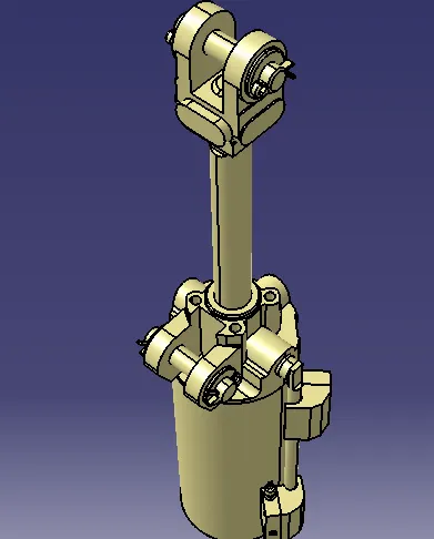
EXPLANATION:
CKG - Series of Cylinder
18 - Clevis width=19.5
63 - Bore Size
100- Cylinder stoke in mm
y- End Bracket i.e Double Knuckle Joint (M6 without Tap)
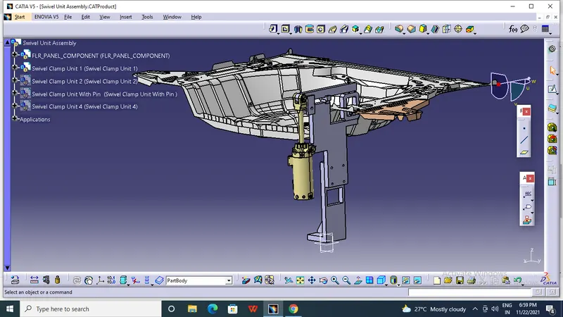
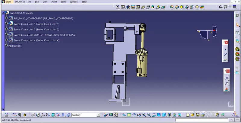
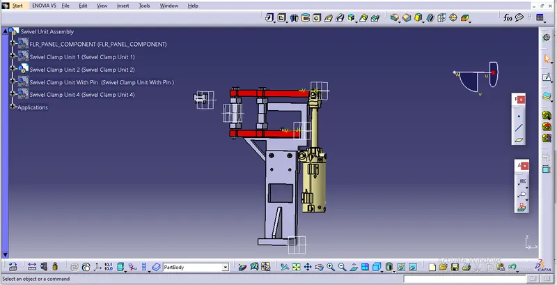
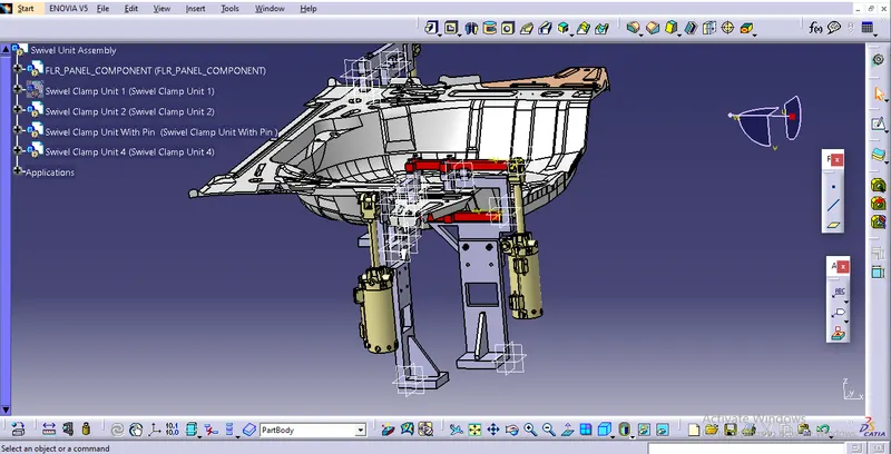
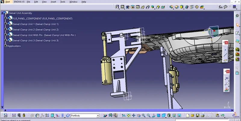
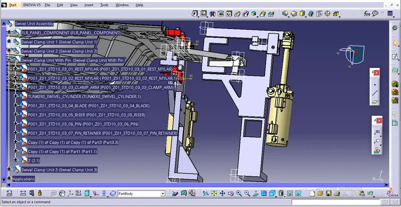
HERE ARE SOME OF THE IMAGES OF THIS SWIVEL CLAMP UNIT PROJECT.
SWIVEL CLAMP UNIT 1
SWIVEL CLAMP UNIT 2
SWIVEL CLAMP UNIT 3
SWIVEL CLAMP UNIT WITH PIN
CONCLUSION:
Thus I designed 3 different types of swivel clamp unit with different riser, blade and clamp arm for given clamp panel.