Week 5:- Rest Unit & Clamp Unit Design Challenge
REST UNIT AND CLAMP UNIT DESIGN-
OBJECTIVE-1) Design three different types of power clamp unit with different type of riser, blade and clamp arm for given car panel.
2) Design two different types of rest unit for the given car panel.
INTRODUCTION-
Clamp unit-
- Clamp unit is designed to clamp/hold car panel with NC blocks/Mylars/rest by using a pneumatic clamp cylinder.
- Clamp unit consist Finger, back-up/ rest mylar, shims/spacer, clap arm, block, pneumatic clamp cylinder, riser.
- The clamp must be placed in such a way that it does not interpret the operation.
- The clamp plan is the data provided by the customer. The clamp plan provides information on the location of pins, rest units, clamp units, Dumps etc.
- It gives the details of the exact position of the clamping locations in form of coordinates.
- The clamp position in some cases will be in such a way that it might damage the tool, or very near to pin position.In such cases, we should not take the decision to change the clamp plan without discussing it with the customer.
Typical parts of a clamp unit as follows
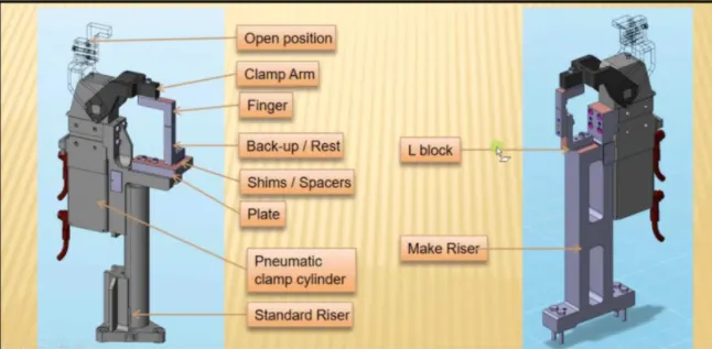
- Finger- A finger is an NC Block, which is mounted on the Clamp arm of the cylinder, and will press the car panels towards the rest, so it holds the car panel.
- Rest- Rest is an NC block, which is fixed to the unit to support the car panel, also resist the clamping forces of the finger, and thus clamps the car panel.
- Clamp Arm- A Clamp arm is a bought- out part, to which all the movable part are fixed, In general, a clamp arm is a part of a clamp cylinder.
- Clamp Cylinder- A Clamp Cylinder is a pneumatic device that works with pressurized air. The Clamp Cylinder is used to open and close the parts fixed to the clamp arm fixed to the clamp body. Clamp arms are generally bought out parts.
3-2-1 Principle
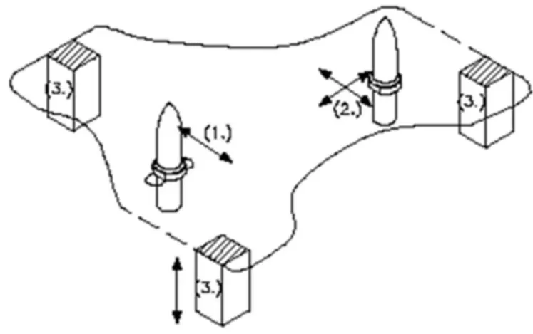
The 3-2-1 method is a work holding principle where three pis are located on the 1st principle plane. i.e eiether XY, YZ, ZX. two pin are located on the 2nd plane which is perpendicular to 2nd plane, and at last one pin on the plane which is mutually perpendicular to the 1st and 2nd planes. The ultimate goal is to constrain the movement of the workpiece along the three axes.
3.Minimum
From the above fig. we can see three locators blocks positioned at te primary locating surface. These three locators restrict the axial upward and downward movement along with it the two radial movements both clockwise and anticlockwise are also restricted, So, total of four radial movements is restricted. So, a total four radial movement is restricted to the two mutually perpendicular axes.
The three locators, on the whole, have restricted six degrees of freedom.
2-Round Locating Pin
The pin added in the location of the hole restricts the axial movements of two perpendicular axes(both positive and negative). Thus, restricting four degrees of freedom.
1-Round locating Pin
The round locating pin is added to the slot in order to restrict the remaining radial movement in both clockwise and anti-clockwise. This, therefore, restricts the remaining two degrees of freedom.
Thus, the 3-2-1 principle is used to restrict the 12 degrees of freedom of a part.
DESIGN METHODOLOGY
1. The designing process is started by giving a project title and proper structuring of the specification tree.
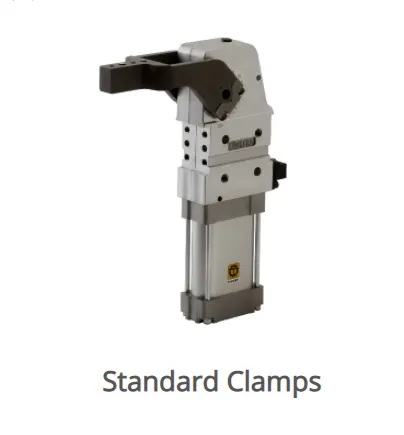
2.The standard pneumatic cylinders and Clamp arm which are the bought-out parts downloaded from the Tunkers website and copied into the project.
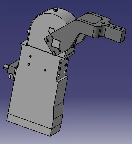
The Rest Mylar and Clamp Mylar are designed and positioned in such a way that the movement of the car panel is restricted. The Clamp Mylars are attached to the Clamp for the open and closing movement.
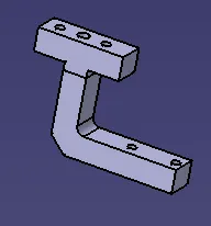
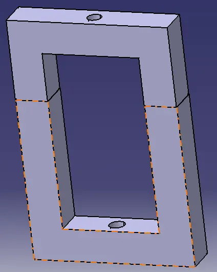
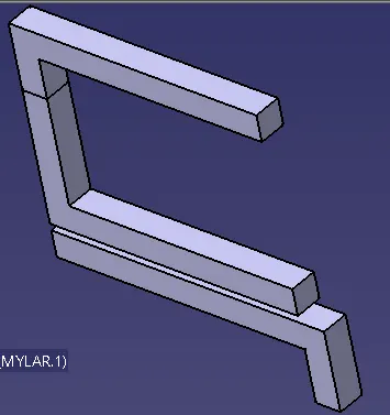
The Riser are designed such that all the above parts are mounted on them. The risers are mounted to the base of the fixture.
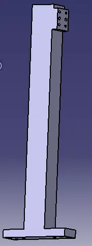
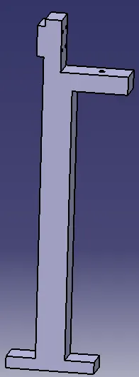
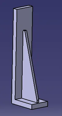
Blades are designed to mount the rest mylar with the Riser. The usage of the blade depends upon the design of the riser and the position of rest mylar.
The parts that are to be assembled are provided with dowel holes and threaded holes.
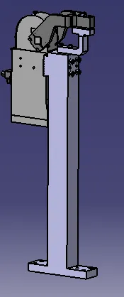
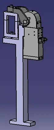
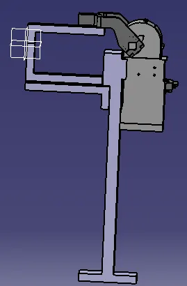
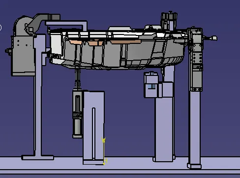
Front view
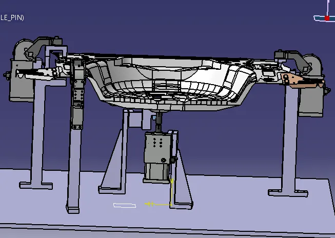
The above image shows the isometric view of the clamp unit assembly with panel.
REST UNIT
- The rest unit are designed to supports the car panels using Mylar.
- The primary purpose of the rest unit is to the rest the car panel.
The parts of rest units are follow
1. Mylar
2. Blade
3. Riser
Mylar
- Mylar is the part that holds the panel from above and below during operation.
- The top side of Mylar is called the Clamping Mylar whereas the bottom side of mylar is called rest mylar.
- Every clamping mylar will have the resting mylar.
- It holds the panel in such a way that it does not deform during welding process.
RISER
- A riser is a part that is used to raise the height of the fixture.
- The riser is fixed to the base of the fixture and the blade is mounted on the riser
- There are two types of Riser 1) L type of Riser 2) Square type of Riser
Blade
- Blades are the plates that are attached to the riser.
Design Methodology of Rest Mylar
1) The Rest Mylar are positioned below the panel in order to support them.
2) The blades are designed to support the rest mylar with the riser.
3) The riser are designed in such a way that it supports the rest mylar.
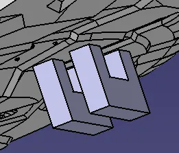
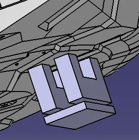
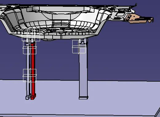
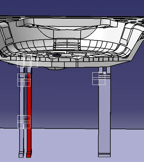
The aboveimages shows the rest unit assembly with the car panel.
CONCLUSION
Hence, the Clamp unit and the Rest unit are designed for the given car panel successfuly.