Week 6 - CHT Analysis on a Graphics card
CHT ANALYSIS ON A GRAPHICS CARD
Aim:
To perform a steady-state analysis on the graphics card model by choosing the appropriate material.
Introduction:
Conjugate means coupled, connected, or related. Heat is defined as the energy transferred by temperature difference. The term conjugate heat transfer analysis allows for the simulation of heat transfer between solid and fluid domains by exchanging thermal energy at the interfaces between them. In solids, conduction often dominates whereas, in fluids, convection usually dominates. Conjugate heat transfer is observed in many situations. For example, forced convection heat transfer through heat exchangers, various electronic equipment, condensers of various refrigerating equipment, IC engines, etc.
Conjugate heat transfer analysis of graphics card model is carried out to identify the heat transfer capability through fins and select the graphics card's proper material. To carry out the mesh independency test and select a suitable mesh size for the analysis and later on analyze three cases to find out changes in heat transfer from the fins by varying the velocity of air.
Geometry:
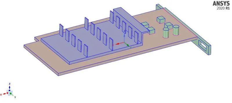
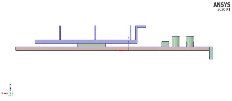
A geometry step file for graphics card was inserted in Ansys Spaceclaim environment. The graphics card consists of three components viz., base, processor, and fins. To generate air flow around the graphics card, an enclosure was created. The share topology is created to reduce the interpolation error and to make the mesh conformal.
Meshing:
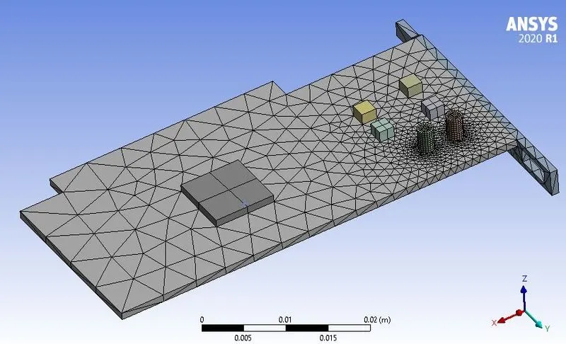
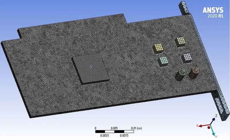
Initially, a baseline mesh of mesh size = 10mm was created and the simulation was carried out for 2 m/s. Then, a well refined mesh of mesh size = 5mm was created and the simulation was carried out for three different velocities (2, 3, and 5 m/s).
| Case | Mesh size | Nodes | Elements | Velocity |
| A (Baseline) | 10 mm | 15872 | 84620 | 2 m/s |
| B (Refined) | 5 mm | 568495 | 3364337 | 2 m/s |
Refined mesh sizing:
| Enclosure | Base | Processor | Fins | |
| Size | 5 mm | 1 mm | 0.2 mm | 1 mm |
| Proximity | Yes (0.1 mm) | Yes (0.1 mm) | Yes (0.1 mm) | Yes (0.1 mm) |
| Curvature | Yes (0.1 mm) | Yes (0.1 mm) | Yes (0.1 mm) | Yes (0.1 mm) |
Baseline mesh:
Refined mesh:
Named selections:
- Inlet
- Outlet
- Symmetry-wall
- Base
- Processor
- Fins
Solution:
A steady-state solver with k-`epsi` turbulence model is used for the simulation.
To assign proper material, different manufacturers use different materials according to the design and availability. Therefore, for this case, the following materials are used.
| Components | Materials |
| Base | Steel |
| Processor | Copper |
| Fins | Aluminium |
Air is considered as the fluid in the enclosure.
Heat source term is added to the processor which is calculated as follows:
Heat generation (W/`m^3`) = `(75 W)/((6.4e-8 ) m^3)` = 117187500 W/`m^3`
Results:
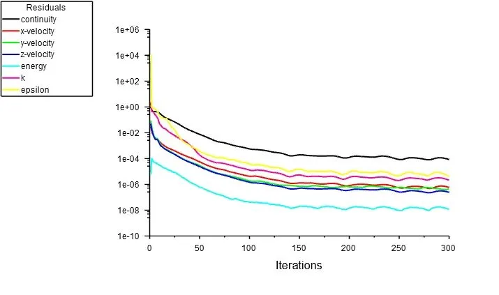
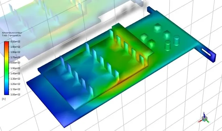
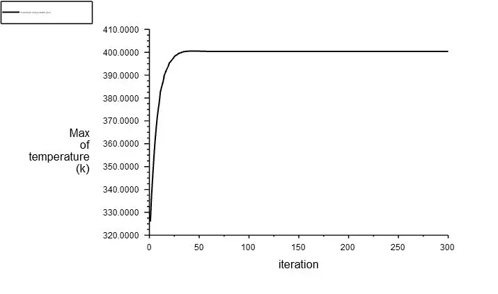
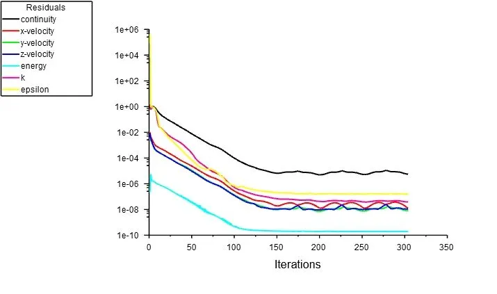
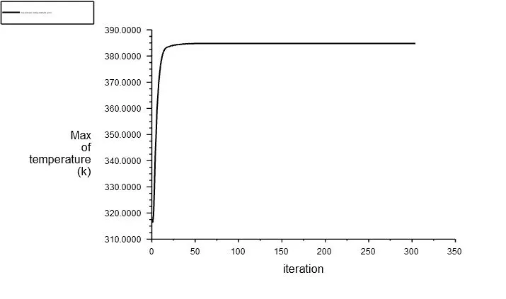
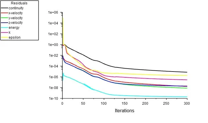
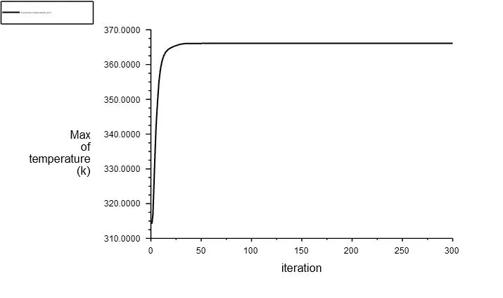
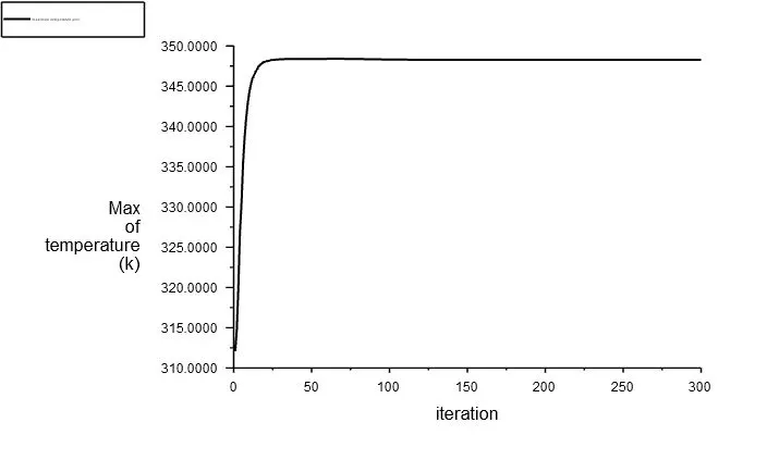
The convergence of the analysis always depends upon the different physical parameters. In our case, the convergence of the result depends upon steady-state heat transfer away from the fins because fins are used to increase the heat transfer rate to air through convection. The heat transfer will not be maximum unless the temperature of the fins reaches the steady-state and change in maximum temperature of the fins with respect to iterations is negligible. That's why the maximum temperature of the fins is important and needs to be maintained at a steady-state.
Case A: Baseline mesh (Mesh size = 10mm; Velocity = 2 m/s)
Residuals:
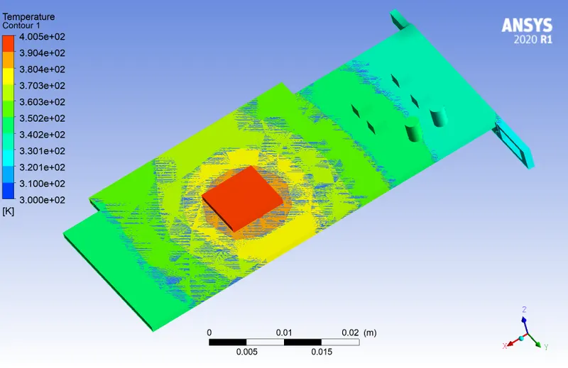
Temperature contours:
Maximum temperature plot:
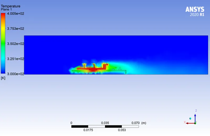
Temperature contour on y plane:
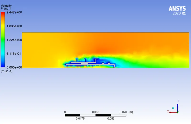
Velcotiy contour on y plane:
Case B: Refined mesh (Mesh size = 5mm; Velocity = 2 m/s)
Residuals:
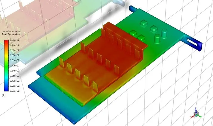
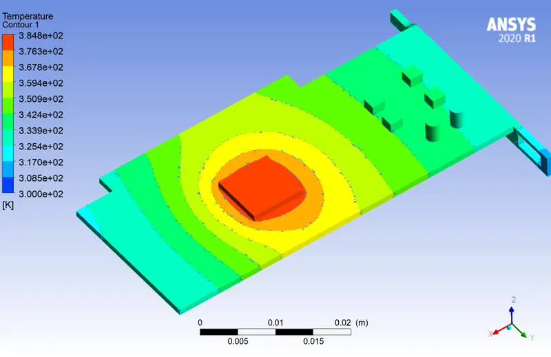
Temperature contours:
Maximum temperature plot:
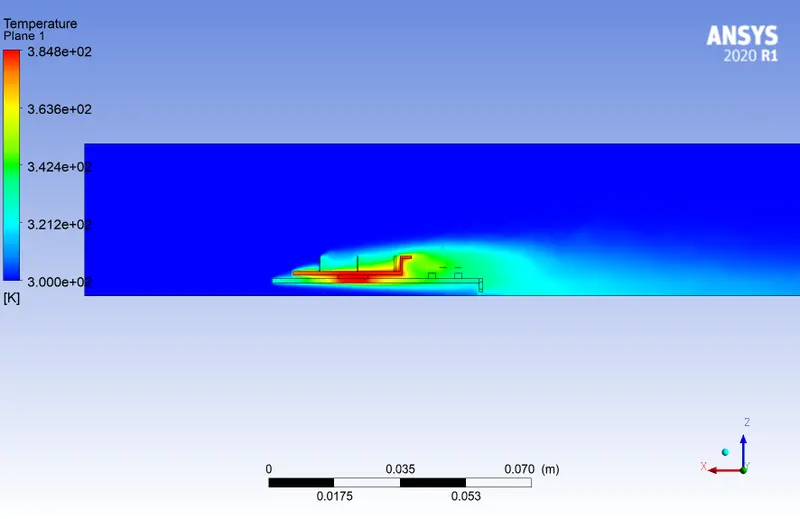
Temperature contour on y plane:
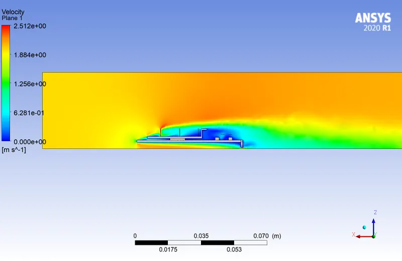
Velcotiy contour on y plane:
Case C: Refined mesh (Mesh size = 5mm; Velocity = 3 m/s)
Residuals:
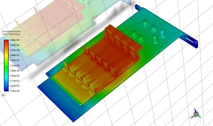
Temperature contours:
Maximum temperature plot:
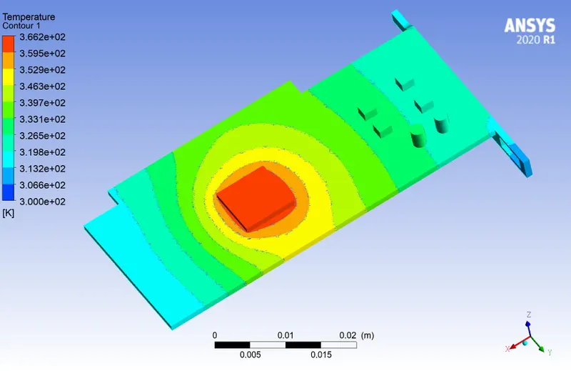
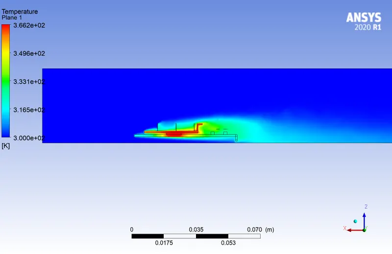
Temperature contour on y plane:
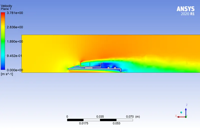
Velcotiy contour on y plane:
Case D: Refined mesh (Mesh size = 5mm; Velocity = 5 m/s)
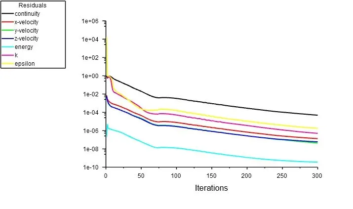
Residuals:
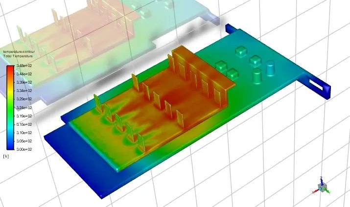
Temperature contours:
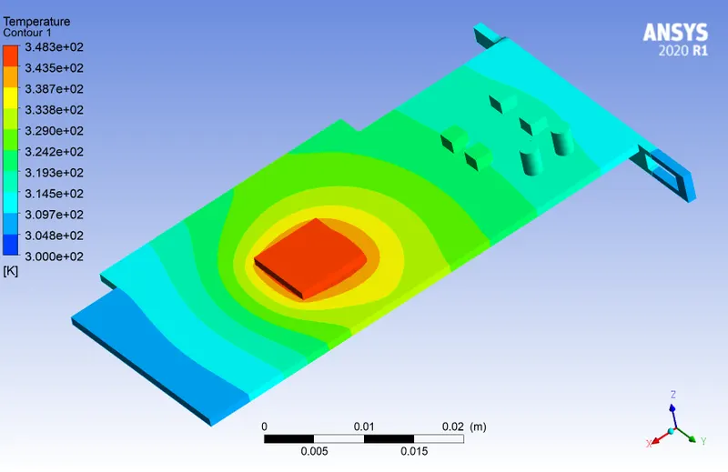
Maximum temperature plot:
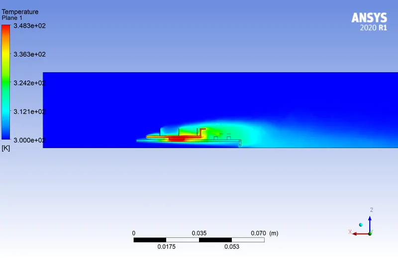
Temperature contour on y plane:
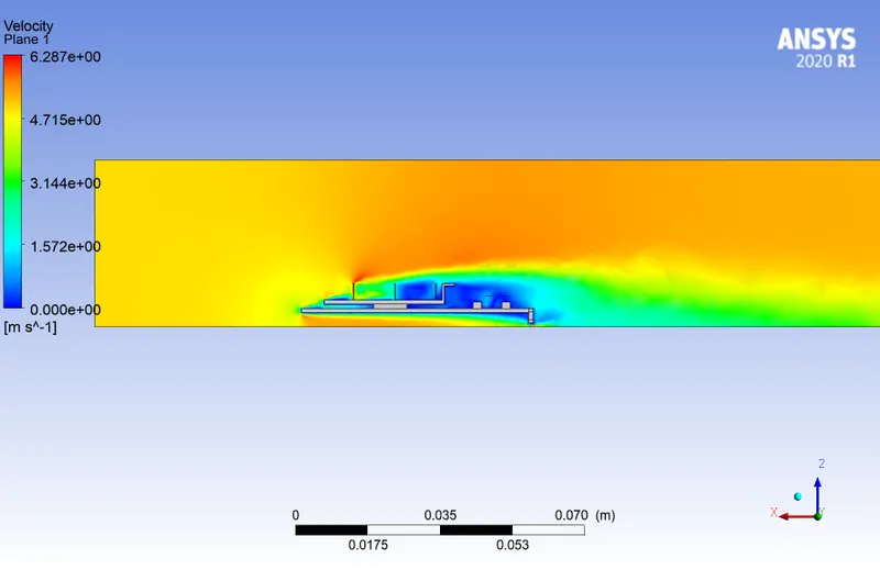
Velcotiy contour on y plane:
Maximum Temperature:
| Mesh type | Fluid velocity (m/s) | Max temperature of fins (K) |
| Coarse | 2 | 400 |
| Fine | 2 | 385 |
| Fine | 3 | 365 |
| Fine | 5 | 347.5 |
From the above table, we can say that the refined mesh gives more accurate results that the corase mesh. The maximum temperature of the graphics card and the fins reduces with an increase in velocity of the air. The temperature reduces with an increase in velocity because it increases heat transfer rate and heat is transferred from fins into the air. The heat transfer coefficient is highest in the region close to the processor since there is no airflow present so that the coefficient remains the same for all changes in velocity.
Conclusions:
- The refined case produces more accurate result when compared to coarse mesh. The time to converge increases exponentially.
- The temperature of the processor and the fins reduce as the velocity of the air increases. This indicates that as the airflow is increased, the rate of heat transfer increases. Hence, the cooling rate of the graphics card also increases.
- The potential hotspot for this problem is the heat source - processor. Apart from that, the airflow is very low in the lower portion of the base. Also, there are no fins provided at that location. This creates the potential hotspot and needs to be resolved.