Week 6 - CHT Analysis on a Graphics card
CHT Analysis on a Graphics card
Objectives:-
- Run the simulation by varying the velocity from 1m/sec to 5m/sec for at least 3 velocities and discuss the results.
- Find out the maximum temperature and heat transfer coefficient attained by the processor.
- Prove that the simulation has achieved convergence with appropriate images and plots.
- Identify potential hotspots on the model.
----------------------------------------------------------------------------------------------------------------------------------------------
Steps in Simulation:
Open Ansys workbench, drag & drop fluid flow (Fluent) onto project schematic. below are steps we need to follow to solve a particular engineering system from CFD standpoint.
- Geometry: Spaceclaim, it is used for import the geometry & other CAD related functions like geometry clean-up etc.
- Mesh: used to generate mesh & other mesh control option there, also assign name which helps during BCs setup.
- Setup: used to define physics of problem, like BCs, material & type of solving method, iterations ect.
- Solution: where runtime results visualization done.
- Results: CFD-Post, where post processing of results will be done.
Geometry Setup-
Import graphics card geometry into spaceclaim.
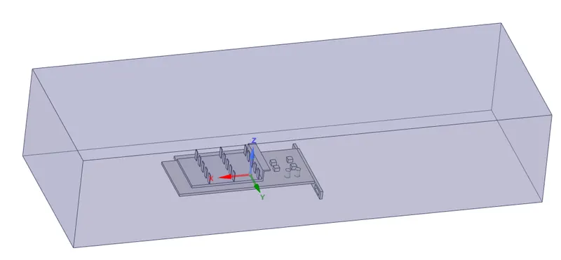
As shown in above figure, we have PCB, Fins, Processor & enclosure in which graphics card is placed. Processor is the main heat generating component which transfers its heat to the to the PCB & Fins.
Mesh Generation-
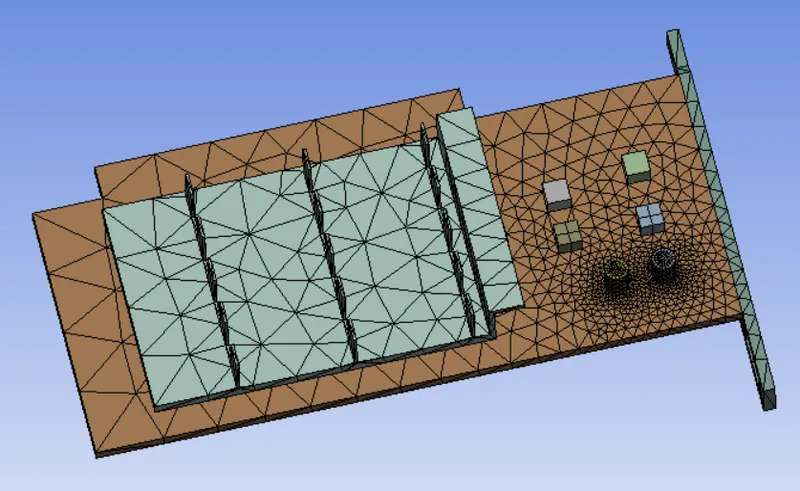
Baseline Mesh: Name selection: Inlet, Outlet & Symmetry
Refined Mesh:
Mesh size= 5 mm
Assign body sizing:
PCB- element size= 1 mm, Fins- element size= 0.5 mm, Processor-element size= 0.5 mm
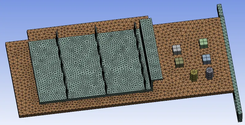
we know processor generates the heat & it transfer to the fins hence we are refining the processor to get much accurate heat transfer coefficient, temp. values.
Fluent Setup:
Setting up physics: Select k-epsilon standard turbulent model.
Solver: pressure based
Assign time as steady state solver.
Material Selection:
For Fluid- air
For solid- aluminium
Properties of Material:
For air: Density= 1.22 kg/m^3
Viscosity= 1.7894e-05 kg/m.s
For aluminium: Density= 2719 kg/m^3
Cell zones:
Assign zones as fluid type for enclosure & solid type for PCB, Fins & processor.
Edit processor & assign energy value as 1e8 w/m^3.
Setting Boundary Condition:
For Inlet:
Velocity= 1,3,5 m/s
Temperature= 300 K
Outlet:
Pressure= 0 Pascal.
Assigning different Flow quantities:
- Create temp. contour
- Standard initialize & run the simulation
CFD Result:
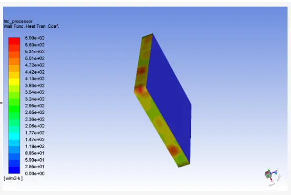
- Check heat transfer coefficient wall.
- Create plane along which temperature, heat transfer coefficient & velocity will be shown.
Results & Plots:
Residuals Plots
Baseline mesh Refined mesh
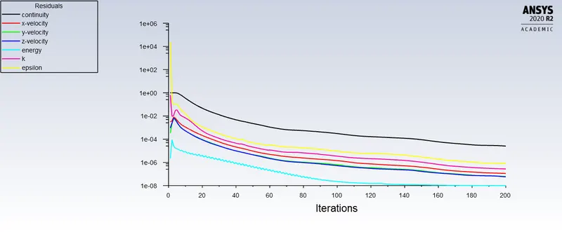
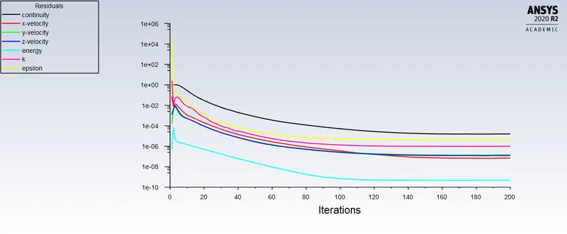
In Baseline mesh solution is converged at 62 iteration.
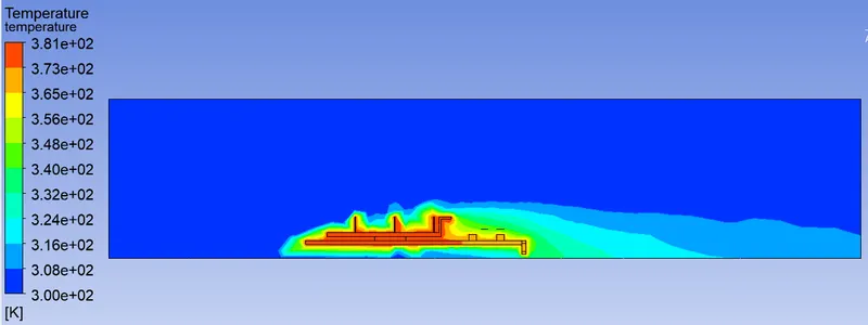
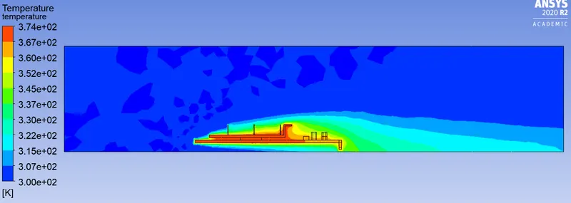
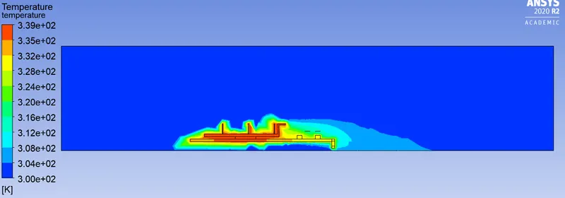
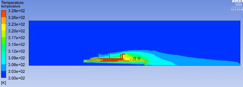
Temp. plot at midplane of baseline & refined mesh- For velocity 1 m/s
Baseline mesh Refined mesh
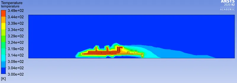
For velocity 3 m/s
Baseline mesh Refined mesh
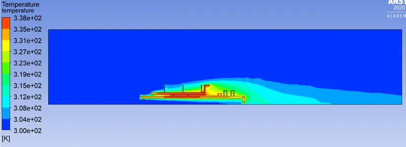
For velocity 5 m/s
Baseline mesh Refined mesh
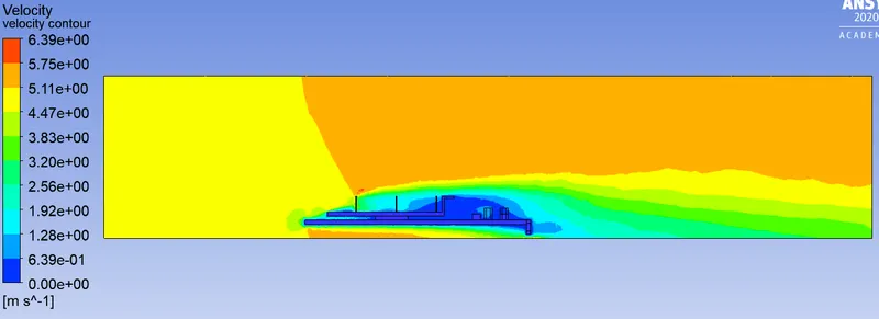
Velocity plot for baseline & refined mesh- For velocity 1 m/s
Baseline mesh Refined mesh
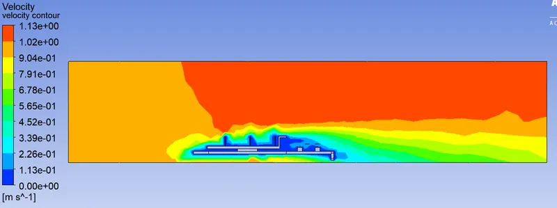
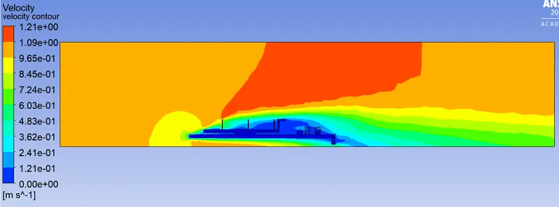
For velocity 3 m/s
Baseline mesh Refined mesh
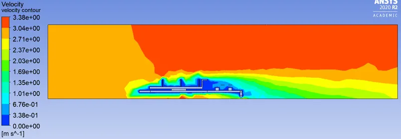
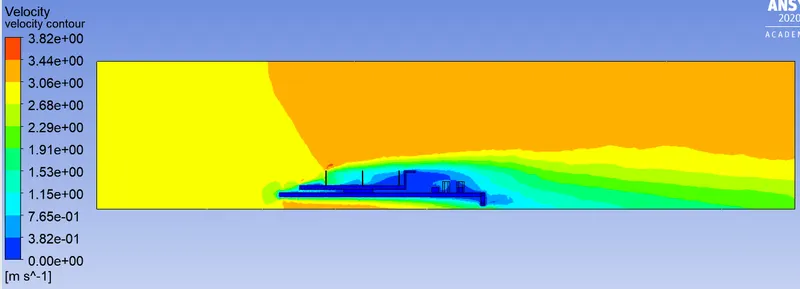
For velocity 5 m/s
Baseline mesh Refined mesh
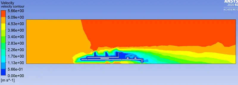
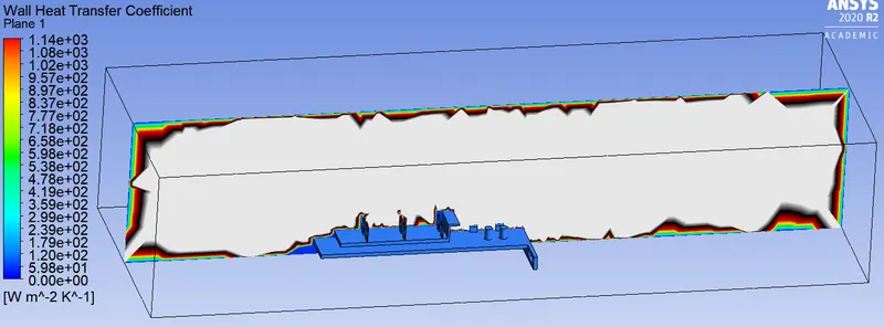
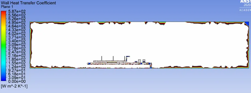
Wall heat transfer coefficient plot for baseline & refined mesh- For velocity 1 m/s
Baseline mesh Refined mesh
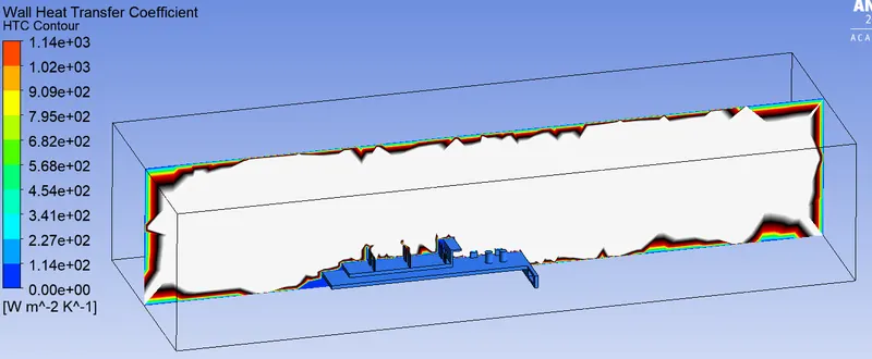
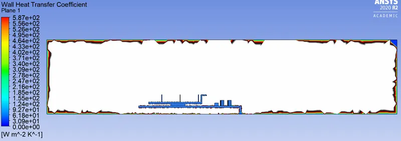
For velocity 3 m/s
Baseline mesh Refined mesh
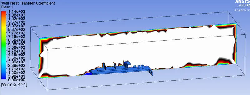
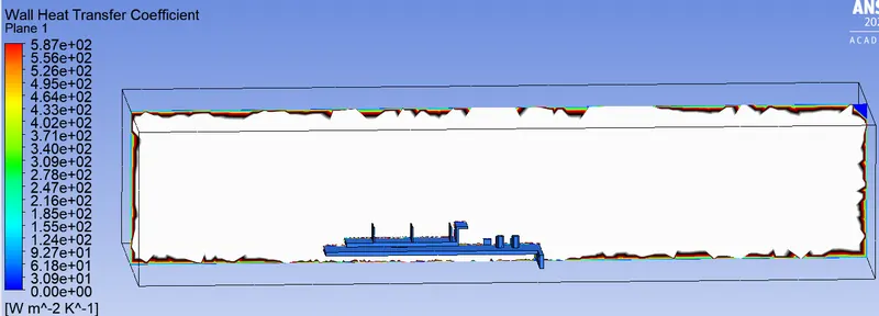
For velocity 5 m/s
Baseline mesh Refined mesh
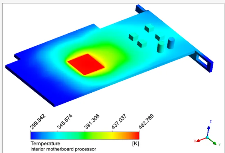
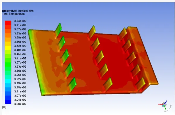
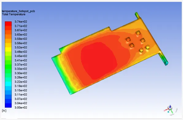
Potential hotspots on model:
Wall heat transfer coefficient on Processor:
Temp. of Fin:
Temp. of PCB:
Temp. distribution on Graphic card:
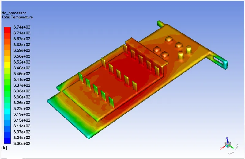
Heat generated by the processor get transfer to the Fins & PCB which are air-cooled.
Comparison b/w Baseline & refined Mesh:
| For Inlet velocity 1 m/s | ||
| Parameters | Baseline Mesh | Refined Mesh |
| Velocity (m/s) | 1.14 | 1.26 |
| Temperature (K) | 380.99 | 374.39 |
| HTC (w/(m^2)k) | 169.13 | 495.48 |
| cells count | 84878 | 384239 |
| For Inlet velocity 3 m/s | ||
| Velocity (m/s) | 3.43 | 4.10 |
| Temperature (K) | 349.46 | 338.46 |
| HTC (w/(m^2)k) | 169.13 | 495.48 |
| cells count | 84878 | 384239 |
| For Inlet velocity 5 m/s | ||
| Velocity (m/s) | 5.76 | 6.89 |
| Temperature (K) | 339.69 | 329.14 |
| HTC (w/(m^2)k) | 169.13 | 495.48 |
| cells count | 84878 | 384239 |
Conclusion:
- In refined mesh, as velocity increases, the heat transfer rate also increases & hence lowers the temp. at the surface of graphics card. But in baseline mesh the values are extremely random.
- As cell counts of refined mesh are more, it has greater accuracy & computation time also increased.