Week 6 - CHT Analysis on a Graphics card
Introduction to GUI based CFD using ANSYS Fluent
Week 6 :- CHT Analysis on a Graphics card
To begin with, the 3-D CAD model of the graphic card is loaded in Spaceclaim and its geometry has following components.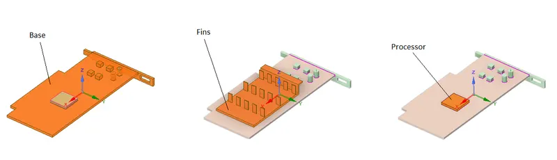
All of these components are enclosed inside an enclosure.
SpaceClaim setup:
The topology of all the sub-parts has been kept shared, as every part is connected via a face and/or an edge.
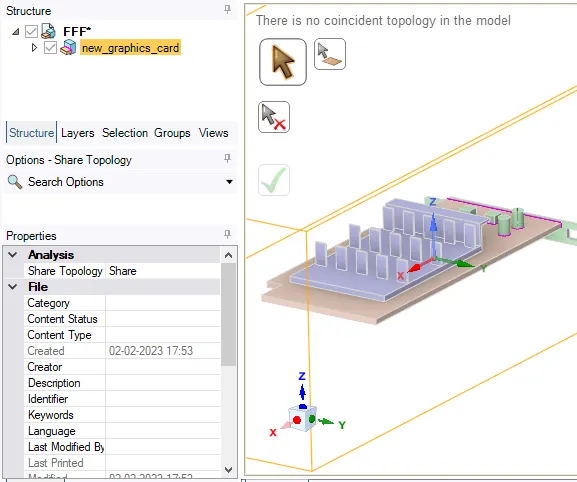
Mesh:
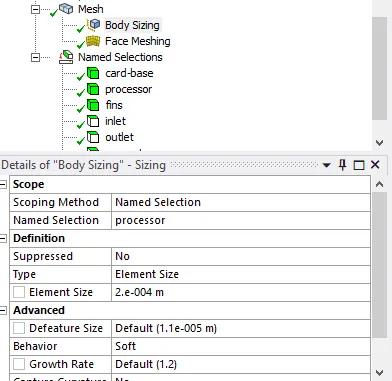
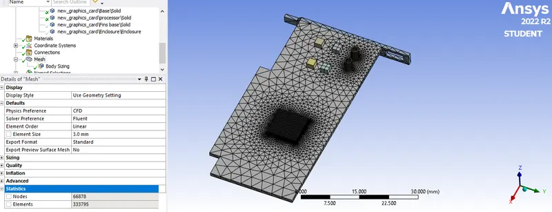
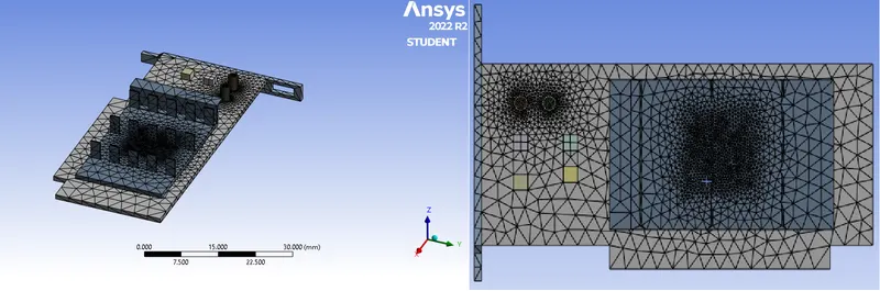
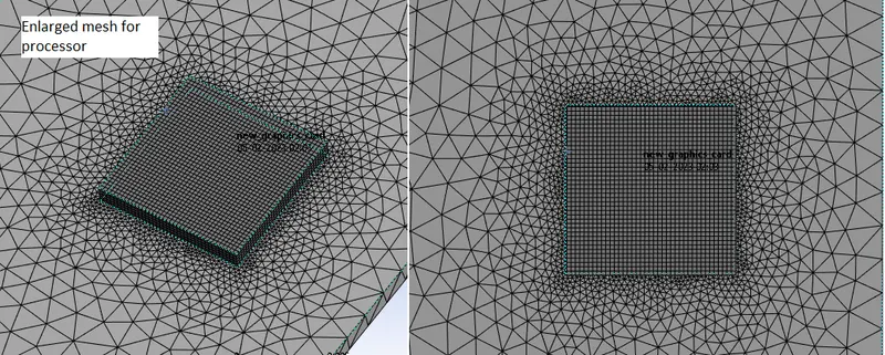
Before creating the mesh, the parts are categorized as named selections and the mesh is generated. For creating the finer mesh on the processor unit, body and face sizing mesh is applied. The total cell count is 333795.
Fluent Setup:
Pressure based solver and steady state analysis is done for the current case. As far as the material selection is concerned, following are the materials chosen;
| Material | Density kg/m^3 | Specific heat J/kg⋅K | Thermal conductivity W/m⋅K |
| Air | 1.225 | 1000 | 0.025 |
| Copper | 8978 | 381 | 387.6 |
| Aluminium | 2710 | 900 | 239 |
| Silicon | 2330 | 710 | 148 |
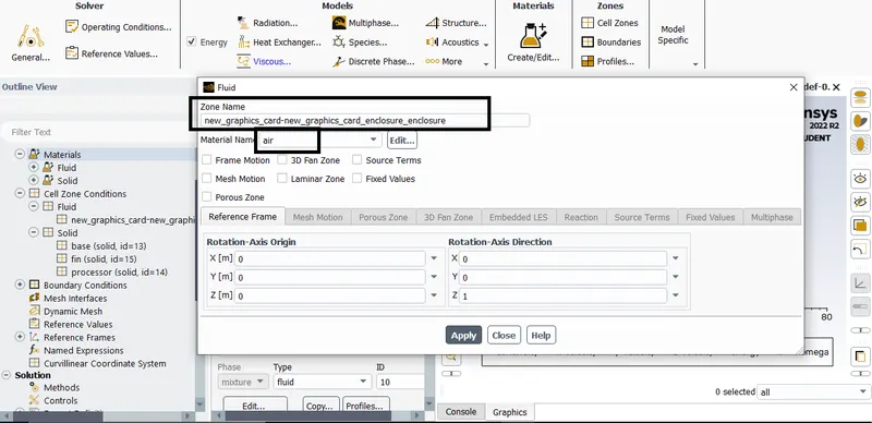
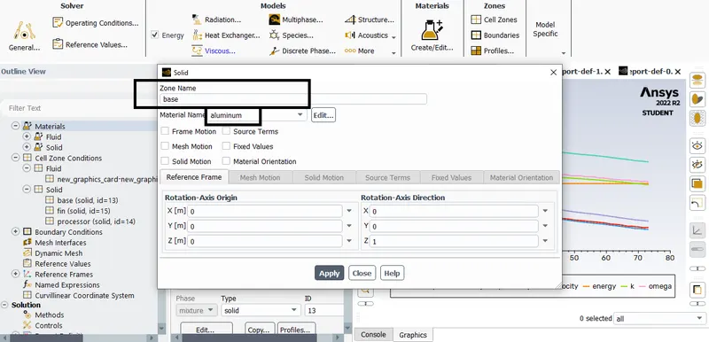
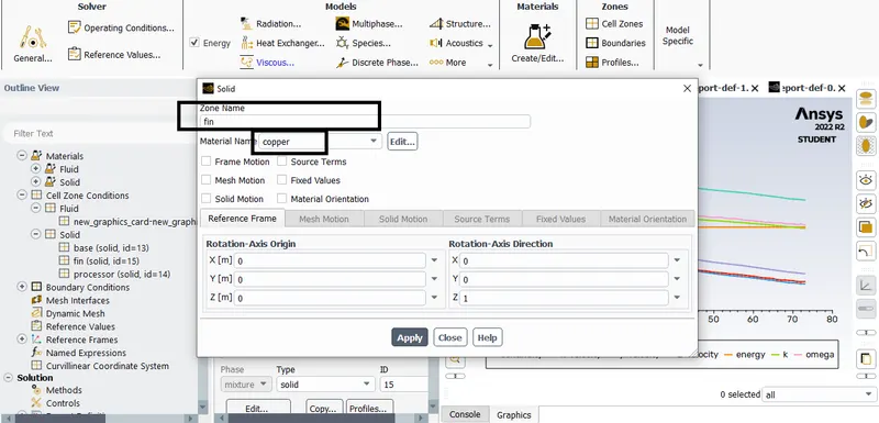
Materials, to the respective parts, under Cell Zone conditions, are given as;
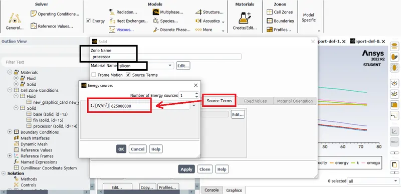
An additional source term is provided for the processor, it generates the heat.
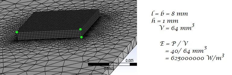
This value can be determined as; consider the GPU consumes 40 Watt of power so the Energy density of the GPU will be Net power input for its volume. The volume of the processor (as a cuboid) will be the product of length, breadth and height, and so these parameters can be calculated in the Mesh by finding the distance between the cells.
The viscous model is selected to k-omega SST.
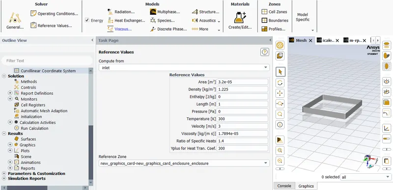
With regards to the reference values, the reference area is 3.2e-5, for the four faces that are in contact with incoming air.
Subsequently, the boundary conditions are as:
| Inlet | Velocity inlet, Temperature = 300 K |
| Outlet | Pressure outlet |
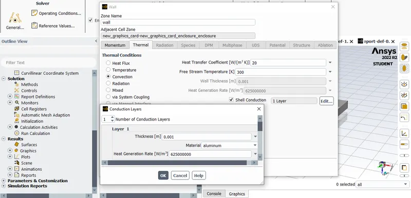
| Wall | No-Slip and Convection |
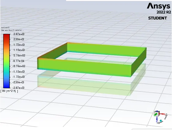
Going for Standard Initialisation, the initial contours of surface heat transfer is obtained as;
The setup is ran for 3 cases:
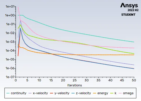
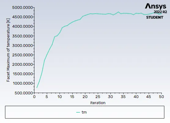
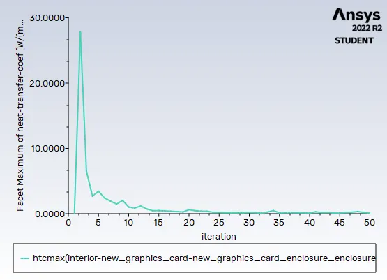
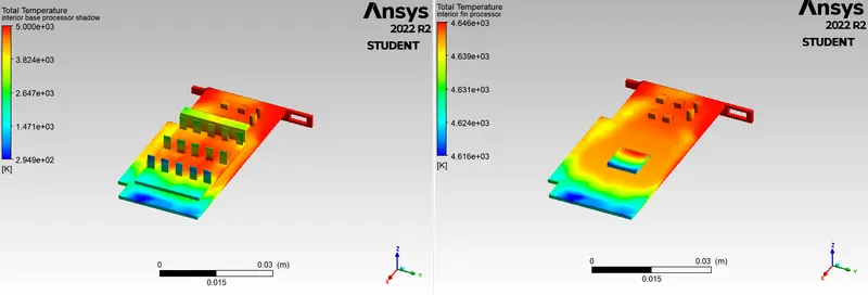
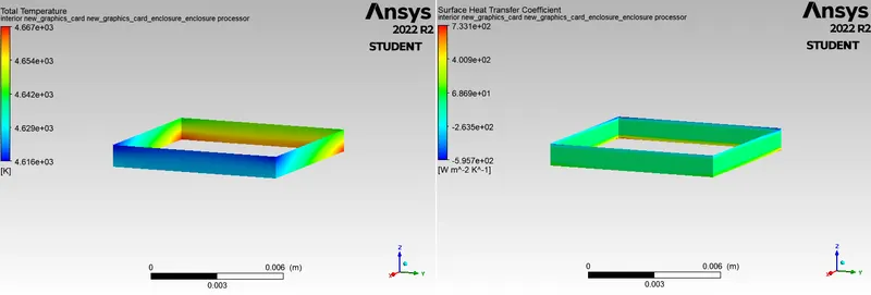
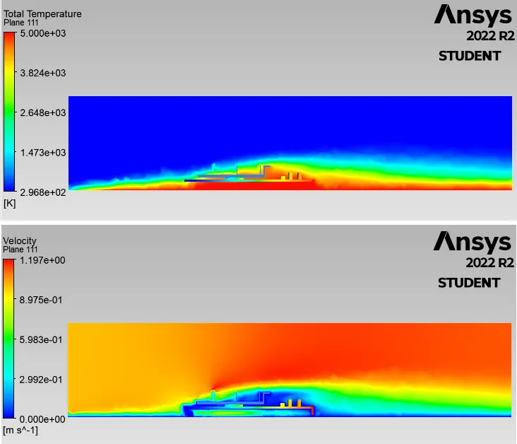
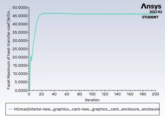
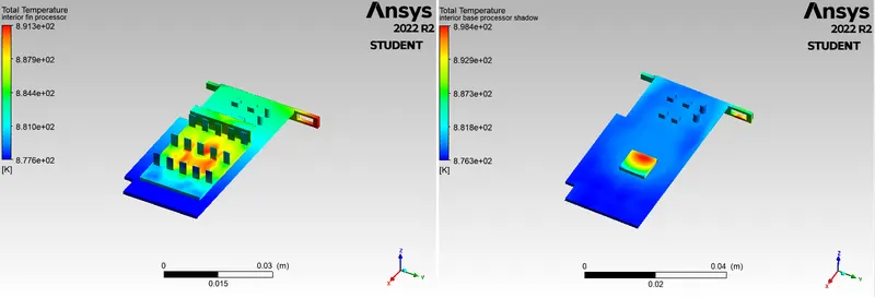
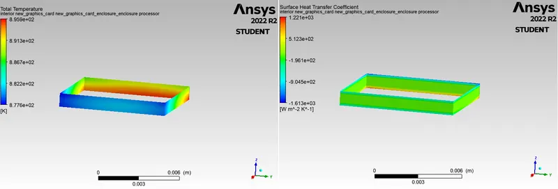
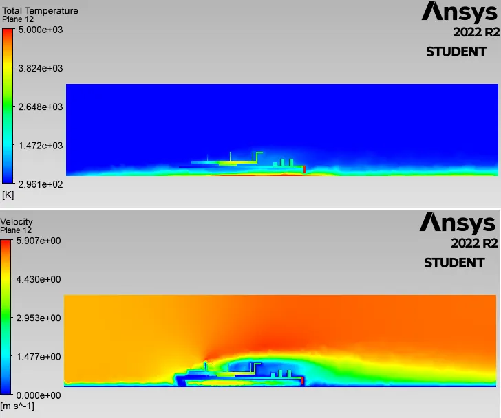
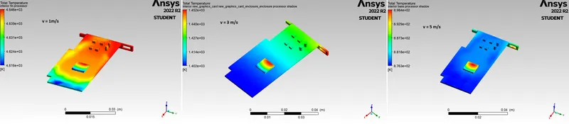
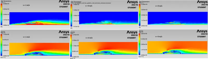
Residuals and contours of temperature, surface heat transfer coefficient and velocity, for card and processor:-
Case 1 : Inlet 1 m/s
Case 2 : Inlet 3 m/s
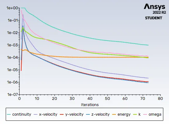
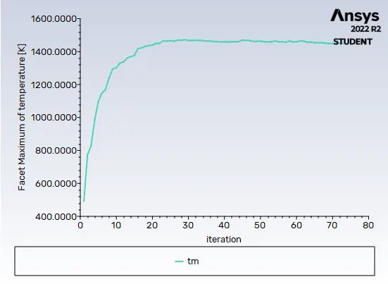
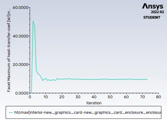
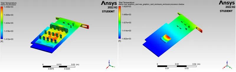
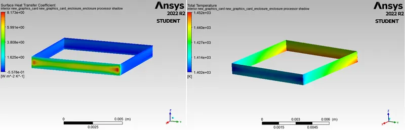
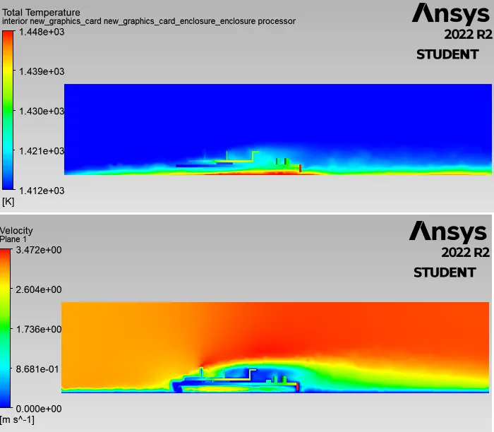
Case 3 : Inlet 5 m/s
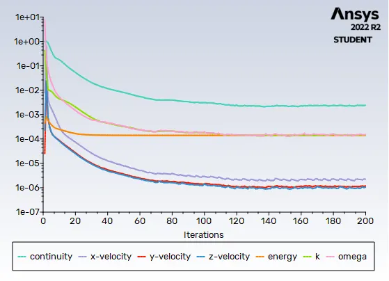
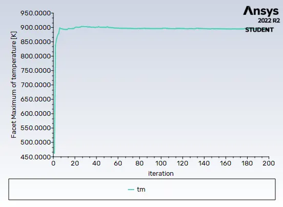
Plots comparison:
| Velocity (m/s) | Max. temperature (K) | Max. surface heat transfer cooefficient (W/m^2.K) |
| 1 | ≃ 4630 | ≃ 2 |
| 3 | ≃ 1430 | ≃ 10 |
| 5 | ≃ 900 | ≃ 46 |
Conclusion :-
As seen from the above values, the surface heat transfer coefficient increases with increment in velocity. This means that the transfer of heat from component to surounding is effective as.
With less incoming velocity, the area near the graphic card fins is more heated as seen in the first contour, and as increasing the velocity, due to forced convection, heat generated is taken away, thereby decreasing the temperature.