Week 6 - CHT Analysis on a Graphics card
AIM: CHT ANALYSIS ON A GRAPHICS CARD
OBJECTIVE:
- To run the simulation by varying the velocity from 1m/sec to 5m/sec for at least 3 velocities and discuss the results.
- To find out the maximum temperature and heat transfer coefficient attained by the processor.
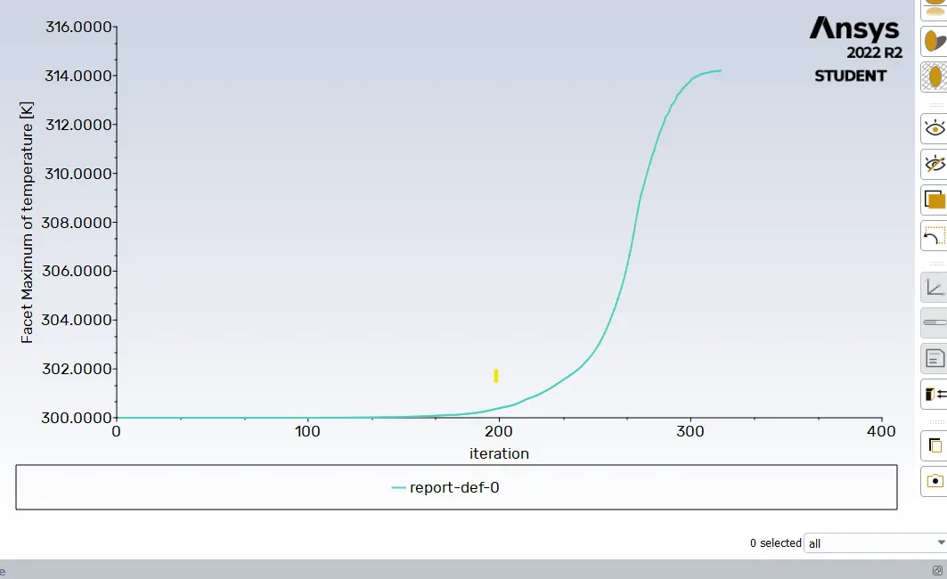
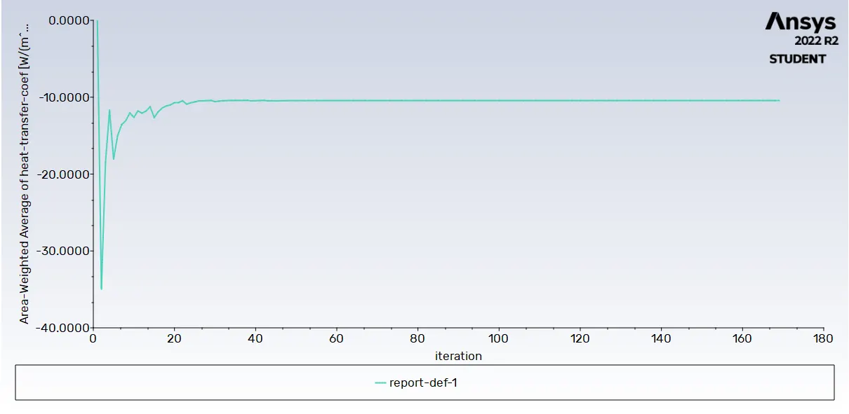
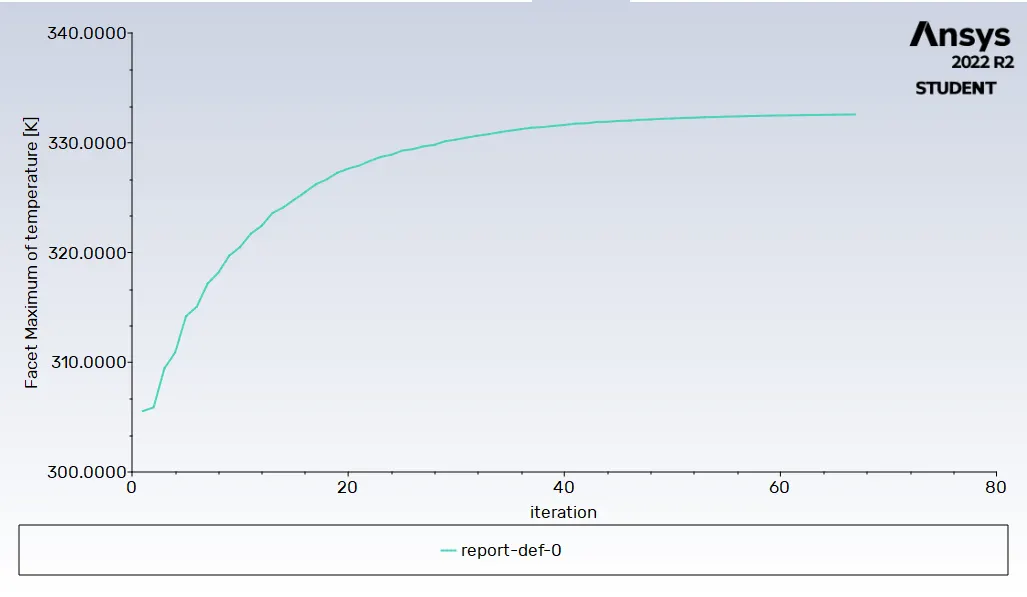
- To prove that the simulation has achieved convergence with appropriate images and plots
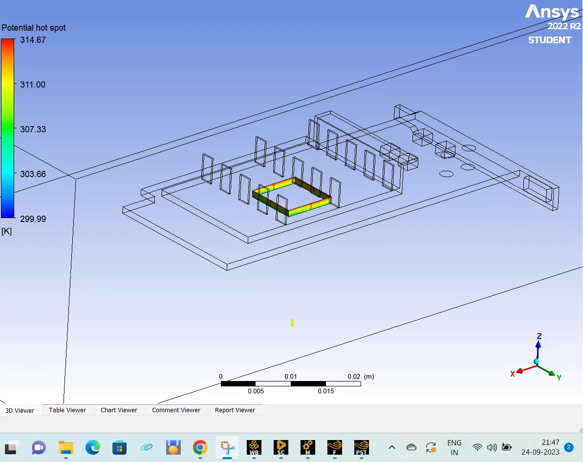
- To identify potential hotspots on the model.
INTRODUCTION:
Mechanisms of Heat Transfer
- Heat transfer is the flow of thermal energy that occurs whenever there is a temperature gradient in a medium. The main mechanisms by which heat is transferred are conduction, convection and radiation. This project deals only with the first two forms.
Heat Conduction:
- Heat conduction happens at a molecular level, where energy is transferred from more energetic particles to less energetic particles. The rate of the heat transfer between two bodies is proportional to the temperature difference between them. The rate of heat transfer per unit area or heat flux is given by Fourier’s law of heat conduction.
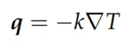
Where,
- q [W/m2 ] is the heat flux density,
- k [W/ (m ·K)] is the material’s thermal conductivity, which may be temperature-dependent, and
- ∇T [K/m] is the temperature gradient.
- The negative sign indicates that heat is transferred in the direction of lower temperature.
Heat Convection:
- Convective heat transfer happens in fluids, both because of the microscopic motion of the constituting particles and because of the bulk fluid motion.
- Depending on the main driving force of the fluid motion, one can distinguish between two forms of convection:
- Natural convection.
- Forced convection.
- Natural convection happens due to the thermal expansion of fluids. The density variations produce buoyancy forces that set the fluid in motion. Most commonly, natural convection happens due to the presence of the gravitational field, which causes warmer, less dense fluid to rise, and colder, denser fluid to sink. However, in general, it can be caused by anybody force that is proportional to the density.
- On the other hand, forced convection happens when the motion of the fluid is caused by an external source, like a fan or a blower, and buoyancy effects are negligible. Mixed convection occurs when both natural and forced convection are present.
- Newton’s law of cooling is often used to model the cooling of an object by convective heat transfer. It states that the rate of heat loss (cooling) is proportional to the temperature difference between the body and its surrounding medium (typically a fluid). Thus, the rate of heat loss is given by,
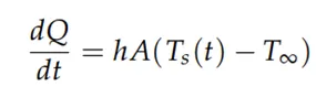
Where,
- Q [J] is the thermal energy,
- Ts is the temperature of the solid body,
- T∞ is the environment temperature, and
- A [m2 ] is the heat transfer surface area.
- The constant of proportionality h [W/(m2 · K)] is the heat transfer coefficient.
GRAPHICS CARD:
- A graphics card (also called a video card, display card, graphics adapter, VGA card/VGA, video adapter, display adapter, or colloquially GPU) is a computer expansion card that generates a feed of graphics output to a display device such as a monitor. Graphics cards are sometimes called discrete or dedicated graphics cards to emphasize their distinction to integrated graphics processor on the motherboard or the CPU. A graphics processing unit (GPU) that performs the necessary computations is the main component in a graphics card
- Electronic devices experience temperature increases when they are steadily supplied with electricity. Thermodynamics dictates that energy transfers can never be 100�ficient, and in the case of a GPU, it is the electrical resistance of the components (mainly capacitors and transistors) that causes the majority of generated heat. This excess heat may damage the components. So this heat should be reduced by natural method or forced method.
HEAT GENERATION IN THE GRAPHICS CARD:
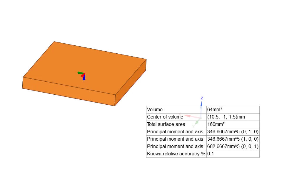
Let us assume that power of the graphics card = 1 W
Total volume of the graphics card = 64*10-9 m3
Heat dissipation = Power/volume
= 1/64*10-9
=0.015625*109
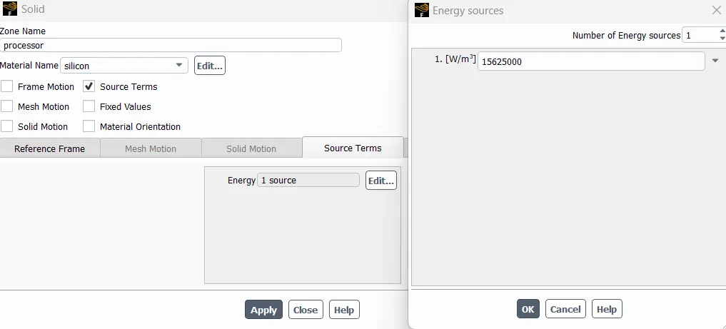
=15625000 W/m3
PROCEDURE:
- Import geomentry in Space claim
- Meshing
- Setup Physics
- Simulation
- Post process
CASE 1: GRAPHICS CARD SIMULATION FOR COARSE MESHING (5MM)
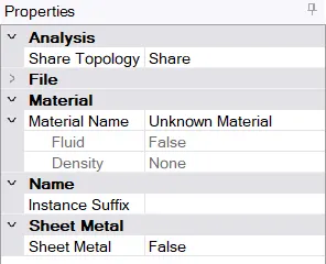
1. Import geomentry in space claim:
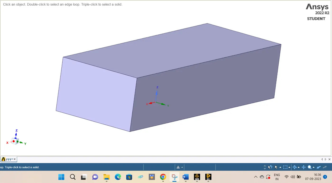
2. Meshing:
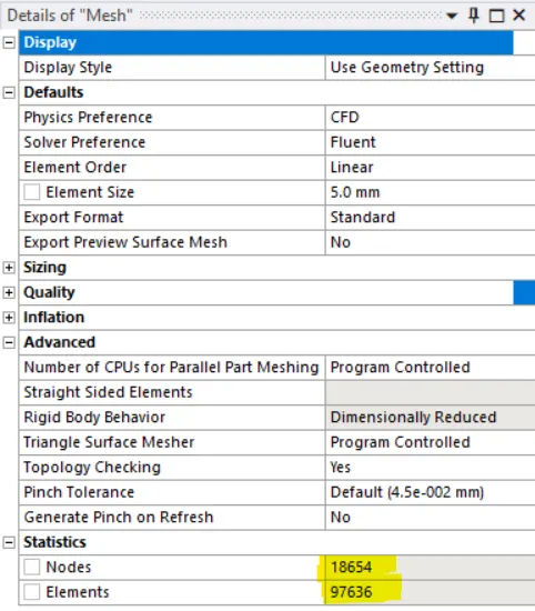
Mesh details:
Naming the appropriate solid components:

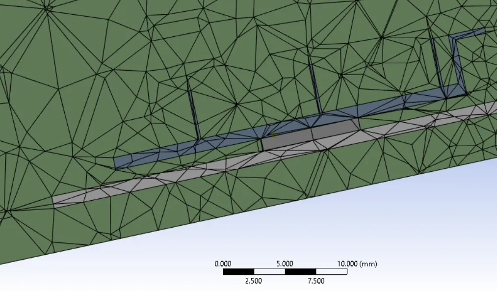
Conformal meshing is done:
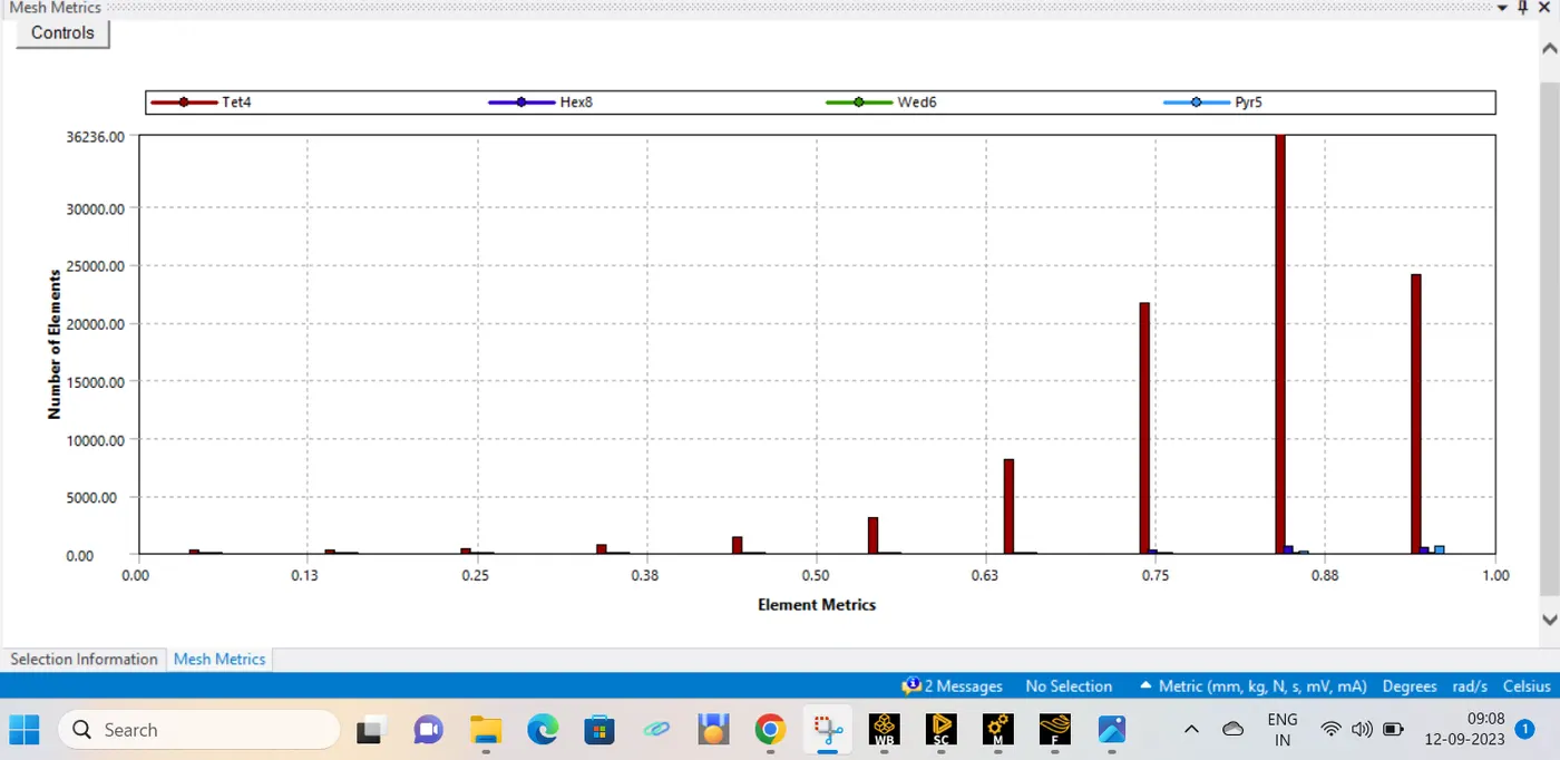
Mesh Matrix:
3. Setup Physics for perfoming simulation:
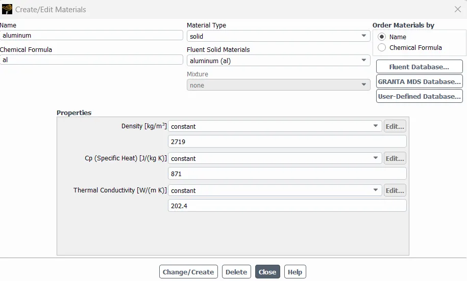
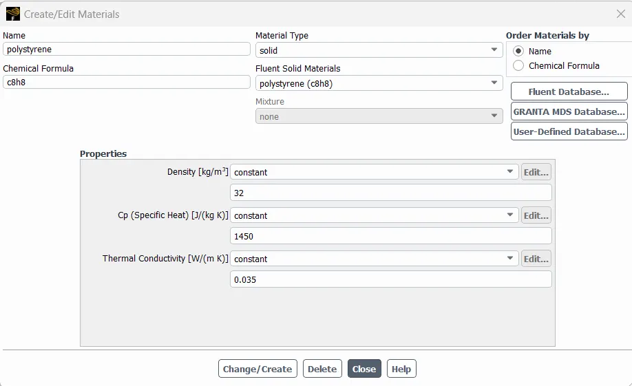
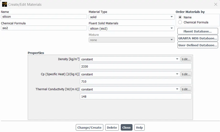
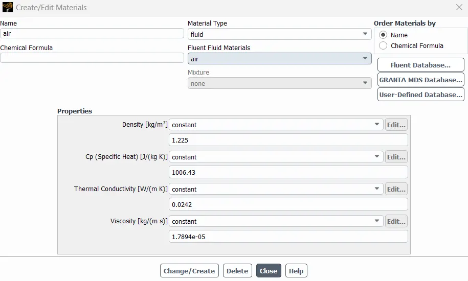
Material creation for each parts in the graphics card:
a)Aluminium
b)Polystyrene:
c)Silicon
d)Air for fluid part
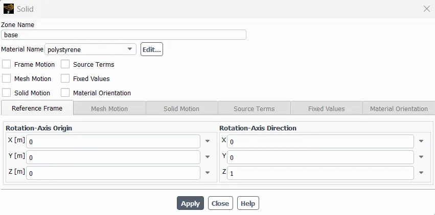
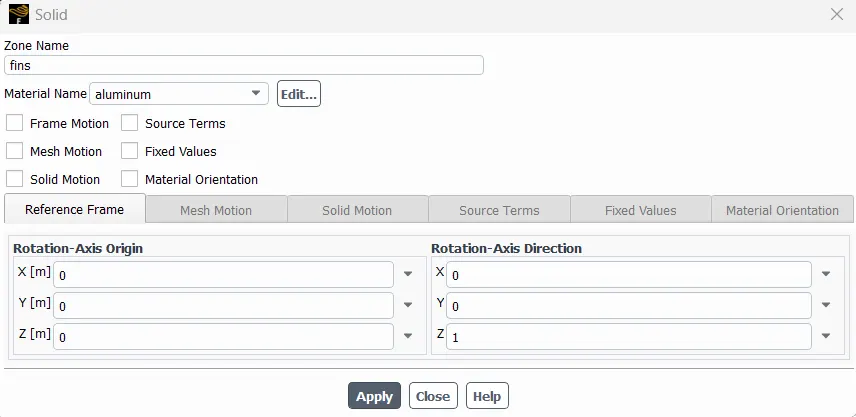
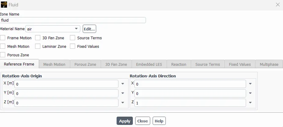
Suitable Material assignment for each parts:
a)Base cell zone is assigned as polysyrene
b)Fins cell zone is assigned as aluminium
c)Processor cell zone is assigned as Silicon and made this zone as heat source:
d)Fluid zone as air:
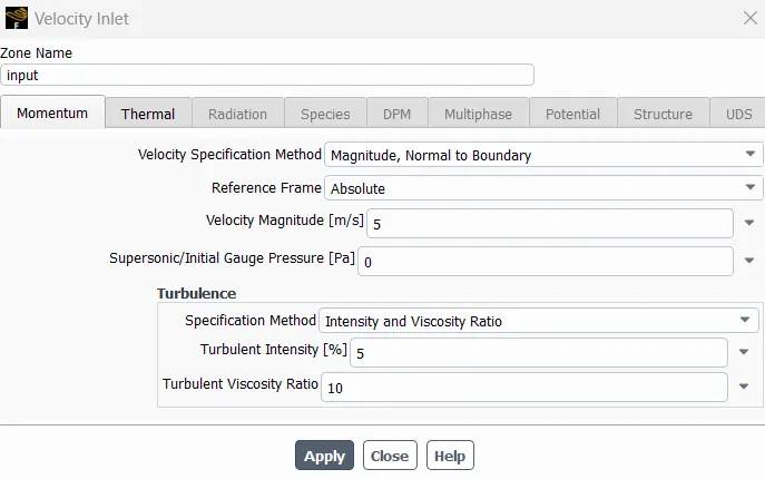
Inlet velocity as 5m/s:
4. Solution after simulation
Contour-surface heat transfer coefficient:
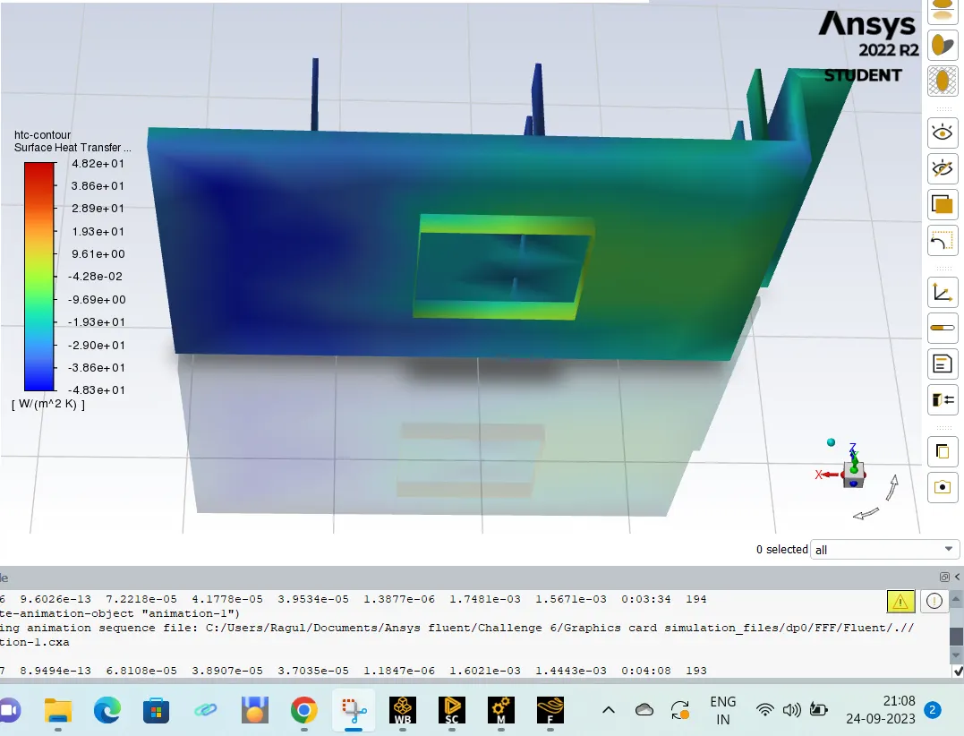
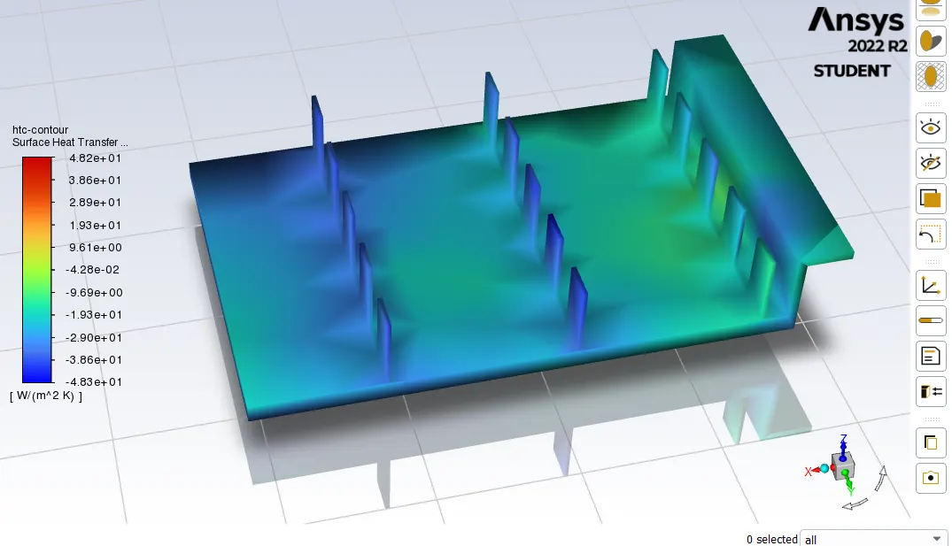
Heat transfer coefficient plot (HTC for processor= -9.5672 W/m2 K)
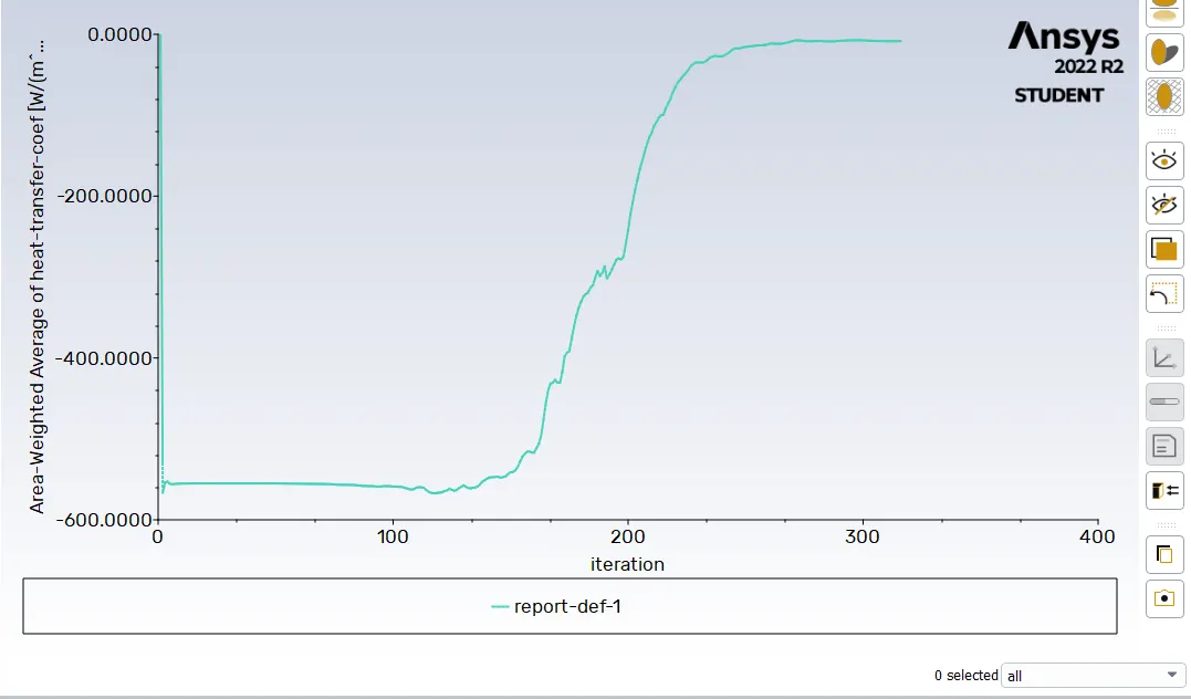
Maximum temperature for processor is 314.214 K
Potential hot spot
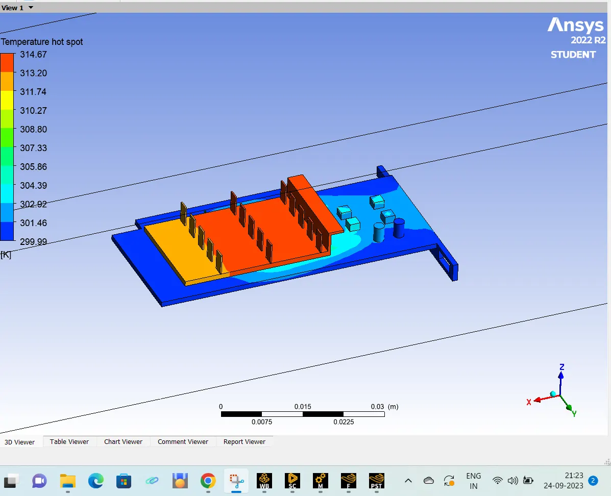
Due to baseline mesh (coarse mesh) it is clear that the temperature is not evenly distributing across the processor.
CASE 2: GRAPHICS CARD SIMULATION FOR FINE MESHING (3MM) FOR INLET VELOCITY OF 5 M/S
- Mesh is refined for each components in the graphics card
- Enclosure mesh size= 3mm
- Graphics card Base mesh size= 3mm
- Graphics card Fins mesh size = 1mm
- Graphics card Processor mesh size = 1mm
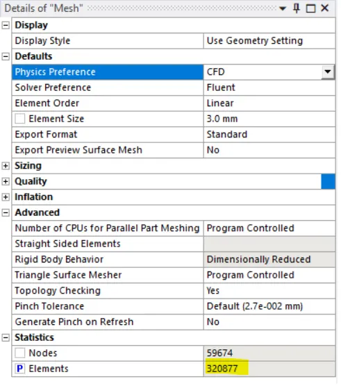
- No of elements = 320877
- Inlet velocity = 5m/s
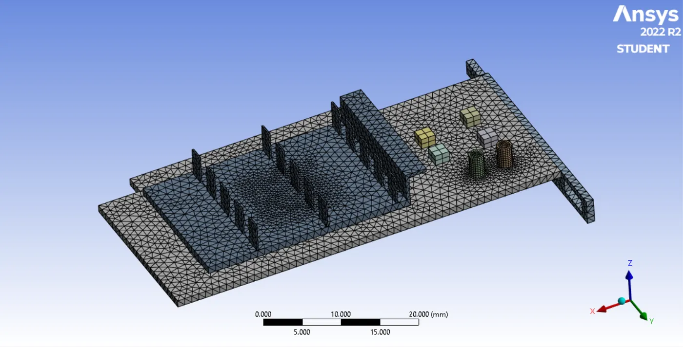
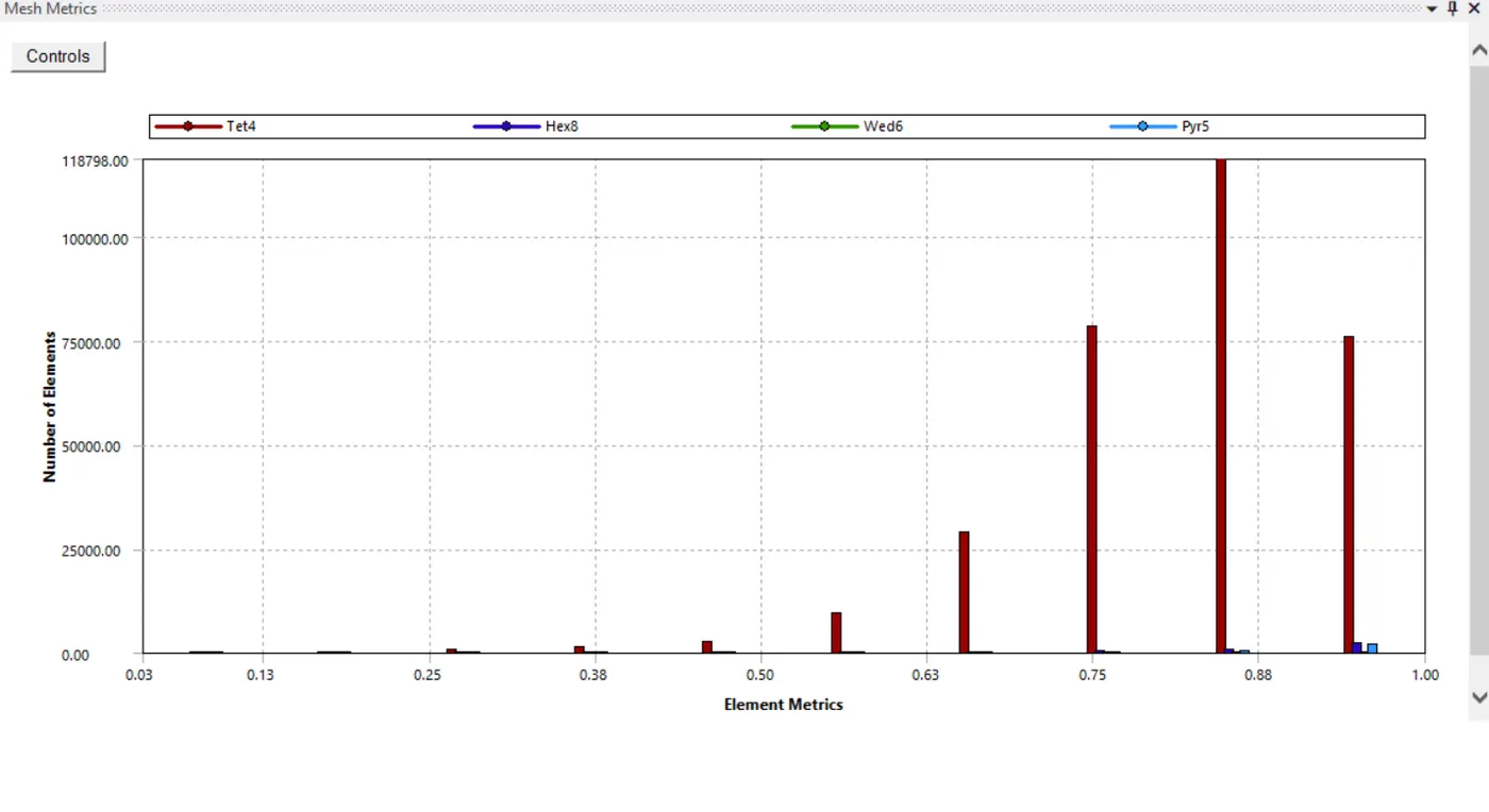
Mesh details:
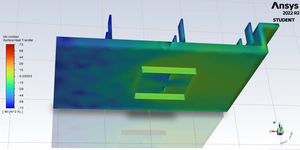

Heat transfer coefficient plot (HTC for processor= -10.2961 W/m2 K)
Maximum temperature for processor is 312 K:
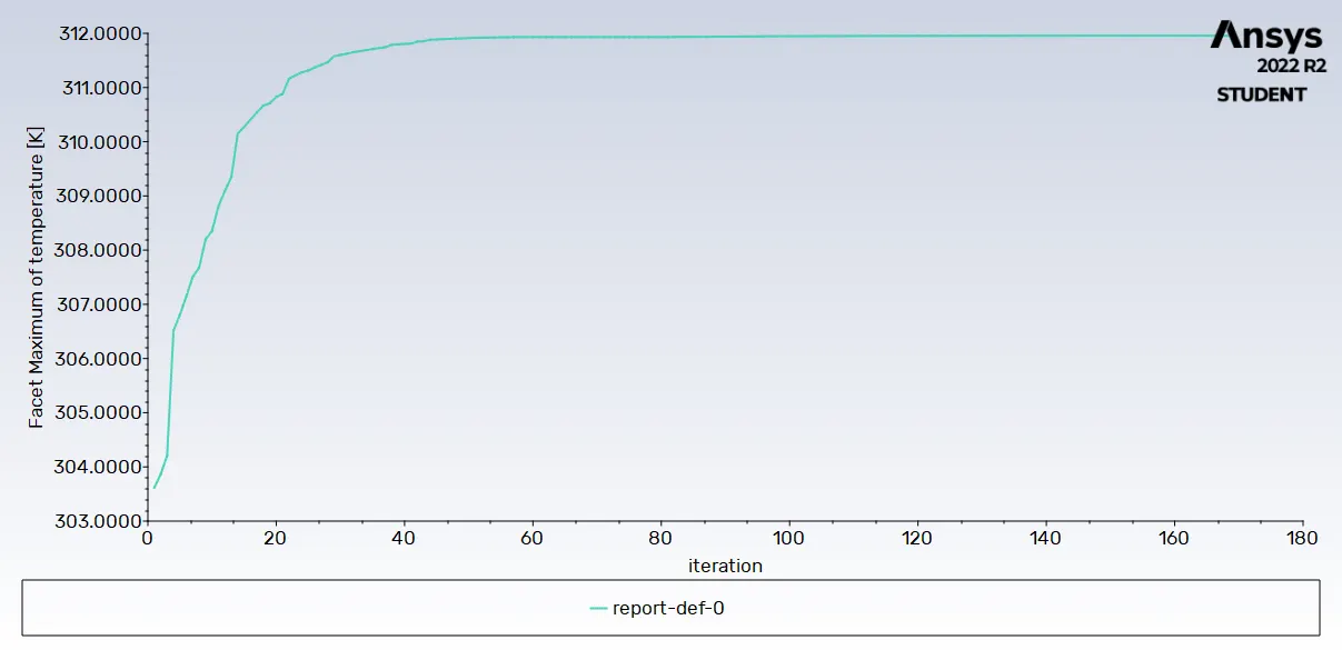
Potential hot spot
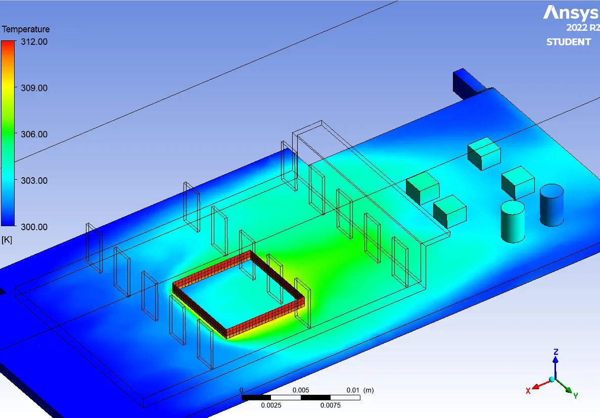
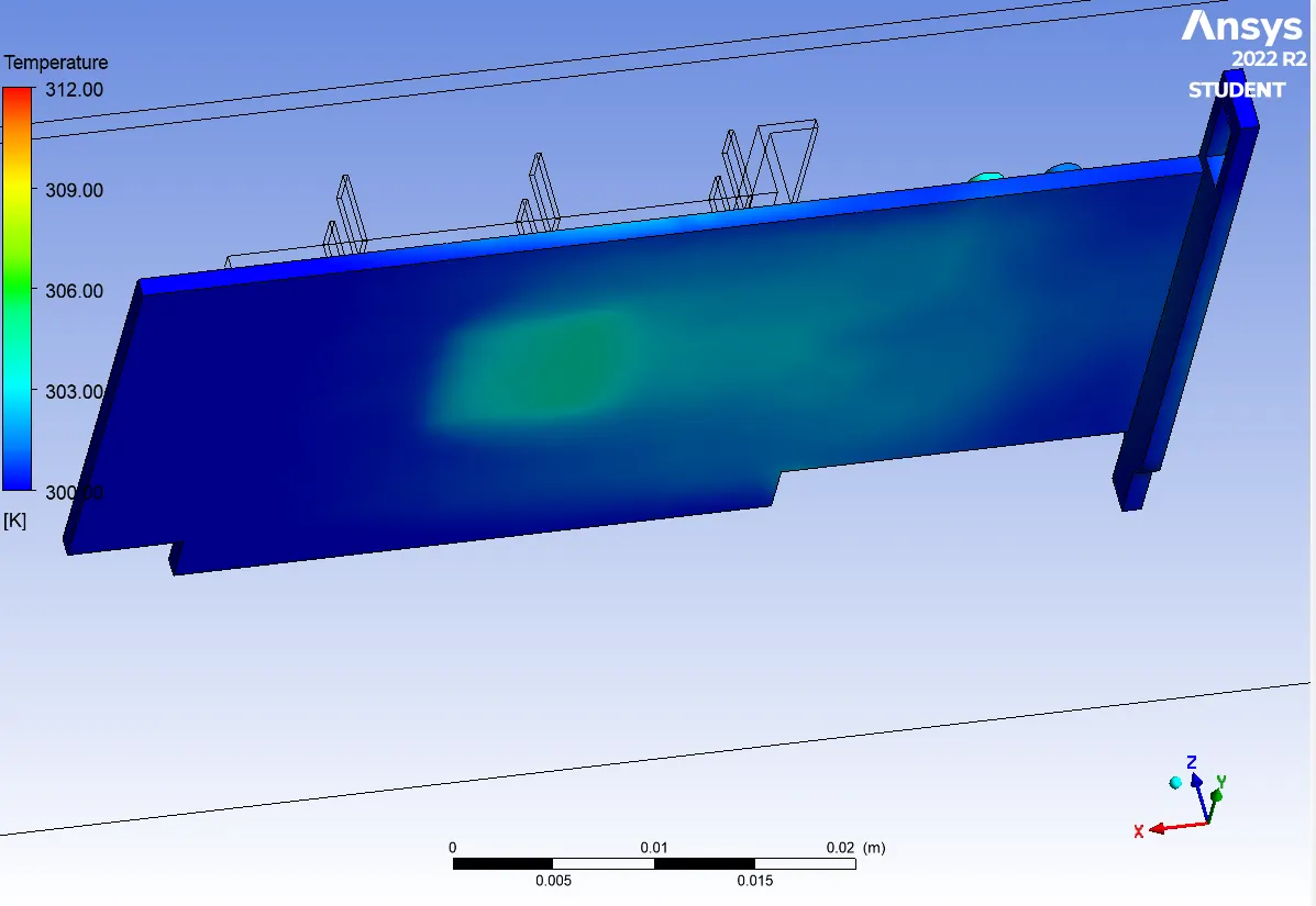
After refining the mesh elements size, the temperature is evenly distributing everywhere in the processor
Volume rendering of Temperature
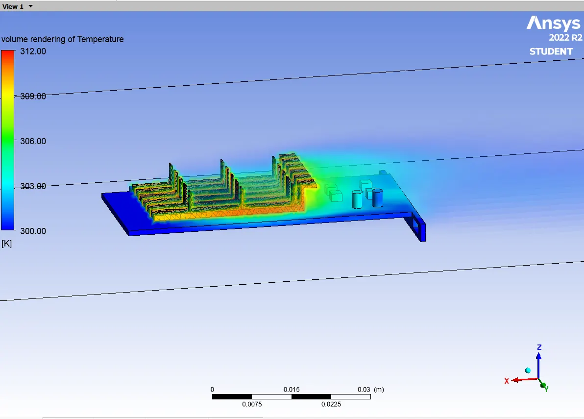
CASE 3: GRAPHICS CARD SIMULATION FOR FINE MESHING (3MM) FOR INLET VELOCITY OF 3 M/S
- Mesh is refined for each components in the graphics card
- Enclosure mesh size = 3mm
- Graphics card Base mesh size= 3mm
- Graphics card Fins mesh size = 1mm
- Graphics card Processor mesh size = 1mm
- No of elements = 320877
- Inlet velocity = 3 m/s
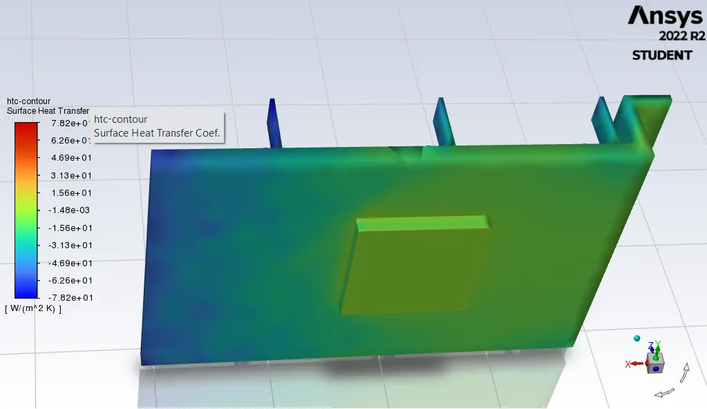
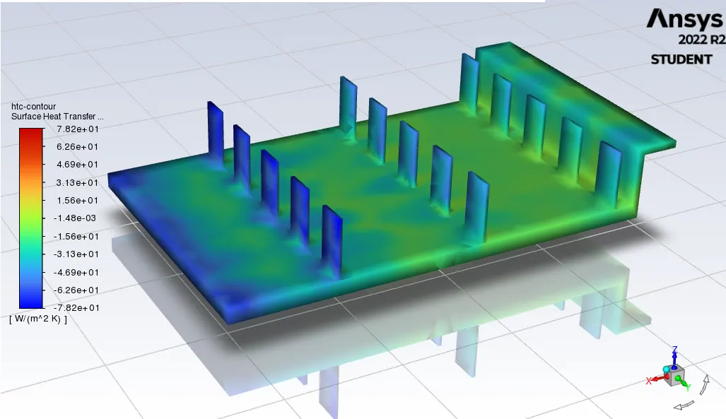
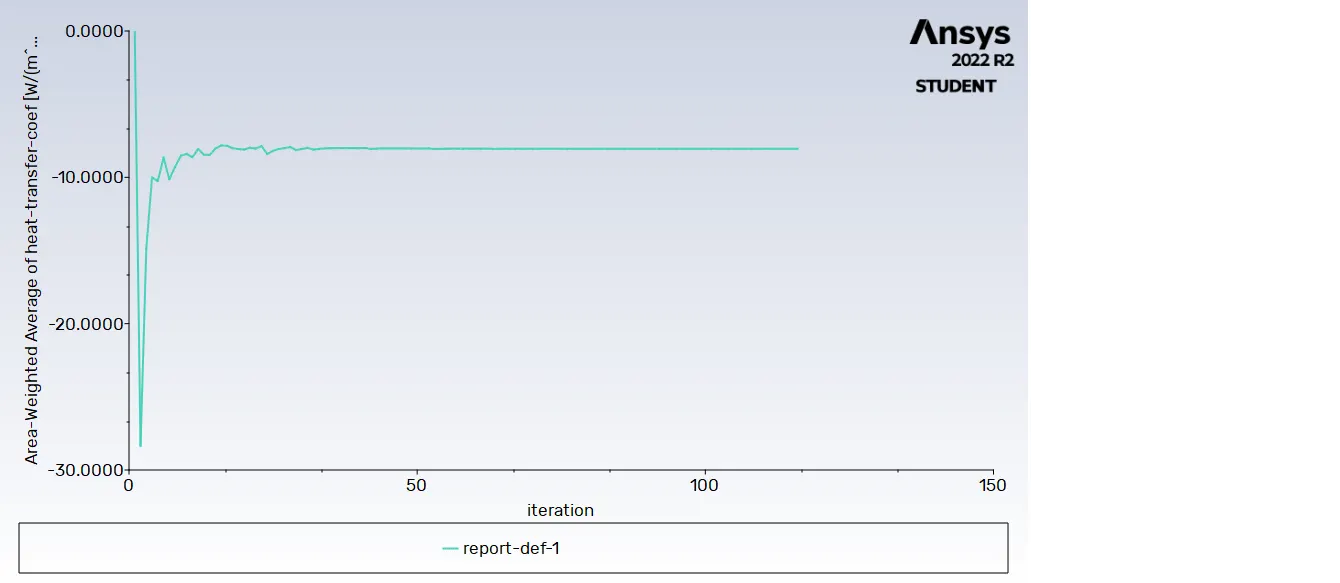
Heat transfer coefficient plot (HTC for processor= -7.9954 W/m2 K)
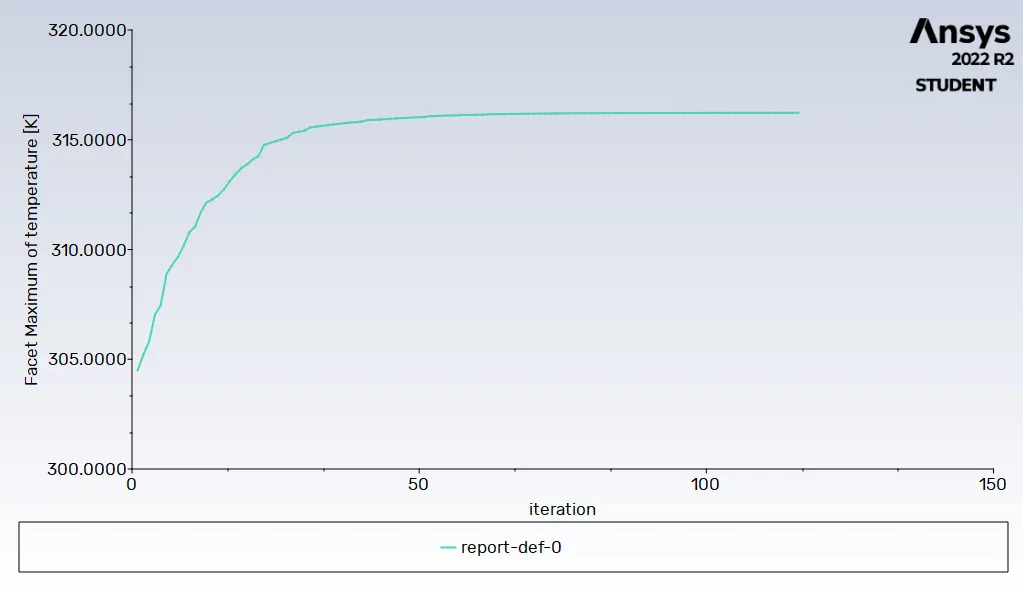
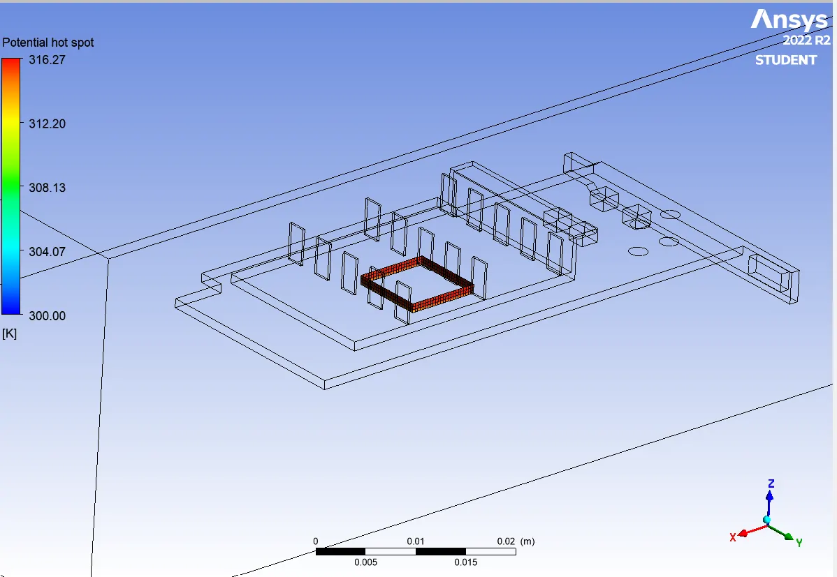
Maximum temperature for processor is 316.218 K:
Potential hot spot:
CASE 4: GRAPHICS CARD SIMULATION FOR FINE MESHING (3MM) FOR INLET VELOCITY OF 1 M/S
- Mesh is refined for each components in the graphics card
- Enclosure mesh size= 3mm
- Graphics card Base mesh size= 3mm
- Graphics card Fins mesh size = 1mm
- Graphics card Processor mesh size = 1mm
- No of elements = 320877
- Inlet velocity = 1 m/s
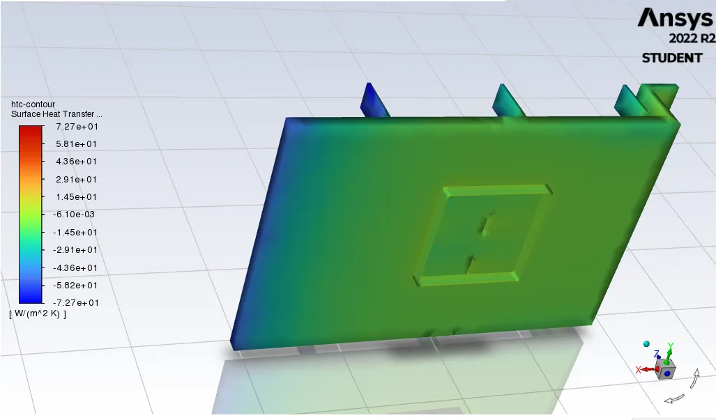
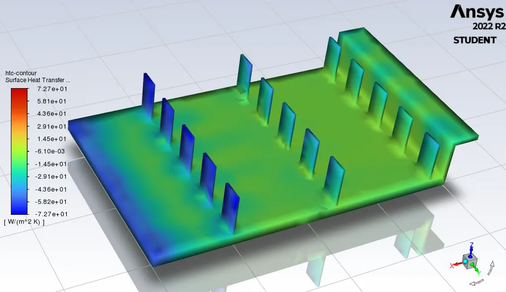
Heat transfer coefficient plot (HTC for processor= -5.5353 W/m2 K)
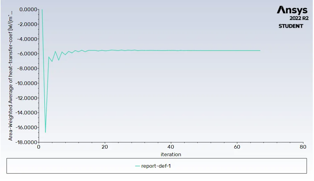
Maximum temperature for processor is 332.5285 K:
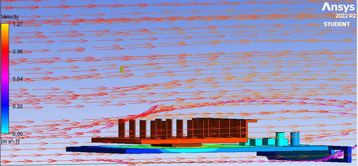
Velocity vector:
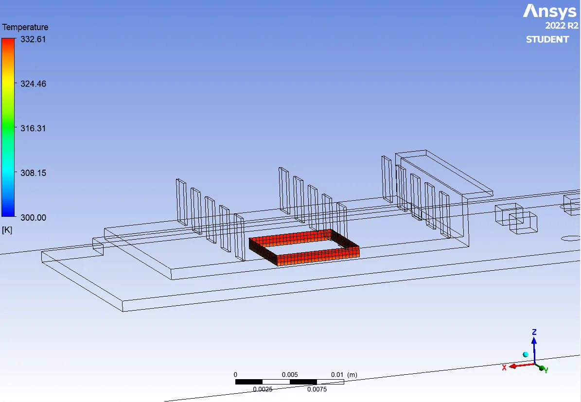
Potential hot spot:
| Inlet velocity (m/s) / Properties of material | Maximum Temperature of processor (K) |
Heat Transfer Coefficient of processor (w/m2K) |
Heat transfer rate (W) |
| 5 ( Coarse Mesh) | 314.214 | -9.5672 | -0.0068 |
| 5 ( Fine Mesh) | 312 | -10.2961 | -0.0069 |
| 3 ( Fine Mesh) | 316.2187 | -7.9954 | -0.0071 |
| 1 ( Fine Mesh) | 332.5285 | -5.5353 | -0.0079 |
CONCLUSION:
- When the inlet velocity is decreased, the processor temperature is increased. This indicates that temperature of the processor is inversely proportional to the inlet velocity of the fluid. This shows that the heat transfer rate is directly proportional to the inlet velocity of fluid.
- The mesh refinement of the components in the graphics card depends on the basis of heat transfer. Here we are focussing about the heat transfer ( conductive and convective ) takes place on the processor and fins region. So mesh elements size is reduced for processor and fins compared with other components in the graphics card.
- As compared with the coarse mesh elements, the fine mesh elements increase the heat transfer process. This could be shown from the decrease of processor temperature from 314.214 K to 312 K with same inlet velocity of the fluid. Due to refined mesh size, the temperature is evenly distributed across the processor.
- As shown from the above graphics, it is observed that heat transfer between two components depends on the thermal conductivity of the each material. More amount of heat is transfered from processor to fins than the base of graphics card. Because base components of the graphics card has a low thermal conductivity than the fins
- Heat transfer coefficient is keep on increasing, when the inlet velocity of the fluid is increased. (1m/s to 5m/s)
- It is clearly observed that the potential hot spot region of the graphics card is processor and its surrounding area. Because of heat source, there is high temperature recorded at the processor region.