Week 6 - CHT Analysis on a Graphics card
CHT ANALYSIS ON A GRAPHICS CARD
Aim
To simulate the conjugate heat transfer analysis on a graphics card using ANSYS Fluent.
Objectives
- Run the simulation by varying the velocity from 1m/sec to 5m/sec for at least 3 velocities and discuss the results.
- Find out the maximum temperature and heat transfer coefficient attained by the processor.
- Prove that the simulation has achieved convergence with appropriate images and plots.
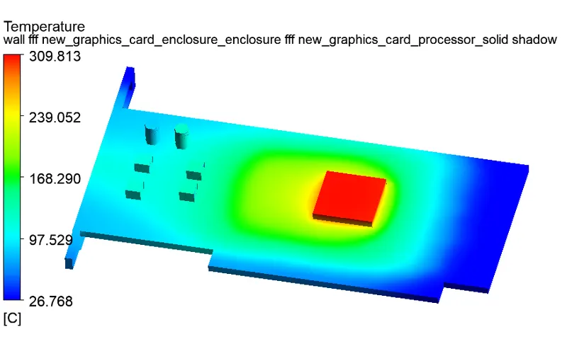
- Identify potential hotspots on the model.
Introduction
- The term "conjugate heat transfer" refers to the blending of fluid and solid heat transfer. While convection often predominates in fluids, conduction frequently predominates in solids. Numerous scenarios show conjugate heat transfer, for instance, heat sinks are designed to combine fluid convection with heat transfer by conduction within the heat sink.
Heat Transfer in a Solid
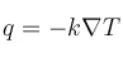
- In the majority of circumstances, Fourier's rule, which states that the conductive heat flow, q, is proportional to the temperature gradient, describes how heat transfer in solids, even if it solely occurs due to conduction:
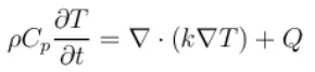
- The temperature field in an immovable solid validates the heat equation in the following form for a time-dependent problem:
Heat Transfer in a Fluid
Three contributions to the heat equation are made because of fluid motion:
- The movement of fluid also involves the movement of energy, which is represented by the convective contribution in the heat equation. Either convective heat transfer or conductive heat transfer may predominate, depending on the thermal characteristics of the fluid and the flow regime.
- Fluid heating is a result of the viscous effects of the fluid flow. Although this concept is frequently disregarded, it contributes significantly to rapid flow in viscous fluids.
- When a fluid's density changes with temperature, a pressure work component enters the heat equation. This explains the well-known phenomenon that, for instance, compressing air generates heat.
- The transient heat equation for the temperature field in a fluid yields the following findings after taking these contributions into account in addition to conduction:

Conjugate Heat Transfer Applications
- The secret to creating efficient coolers, heaters, or heat exchangers is effectively mixing heat transfer in fluids and solids.
- On long distances, fluid often serves as the energy transporter. The most popular method for achieving a high heat transfer rate is forced convection. Combining convection with phase change (such as liquid water to vapour phase transition) might enhance performance in specific applications.
- Solids are still necessary, though, particularly to separate the fluids in a heat exchanger so that they can exchange energy without mixing.
- Heat transmission between two fluids separated by a thin metallic wall is illustrated by the flow and temperature field in a shell and tube heat exchanger.
- Typically, heat sinks are built of high thermal conductivity metals like copper or aluminium. By expanding the region where heat may exchange between the solid component and the surrounding fluid, they disperse heat.
- A power supply unit's temperature field cools as a result of the air flow created by an extractor fan and a perforated grille. The interchange area between the flow and the electrical components is increased using two aluminium fins.
-
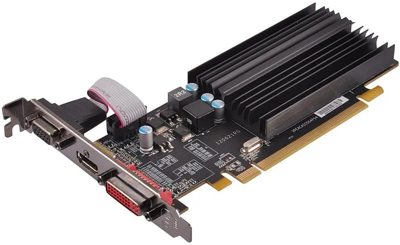
An extension card known as a graphics card produces a feed of output pictures that are sent to a display device (such a computer monitor). The majority of video cards don't have a 6-inch basic output limit. Their built-in graphics processor may do additional work, freeing up the computer's primary CPU to do something else.
Steps for the Simulation:
- Create the geomentry or load the geomentry
- Discretize the geomentry with adaptable mesh element size
- Apply the material and boundary conditions
- Solve the problem
- Interrupt the results
Problem Setup
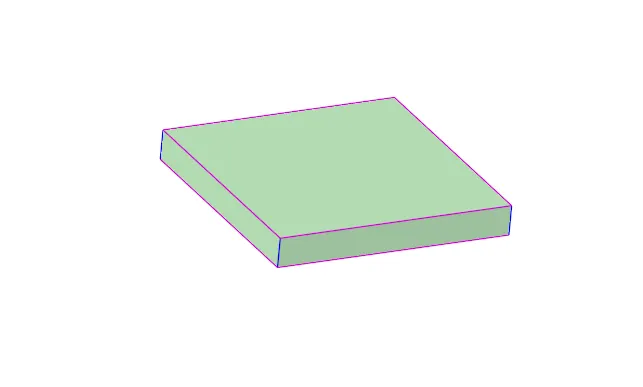
Geometry of Graphics Card's Base Plate
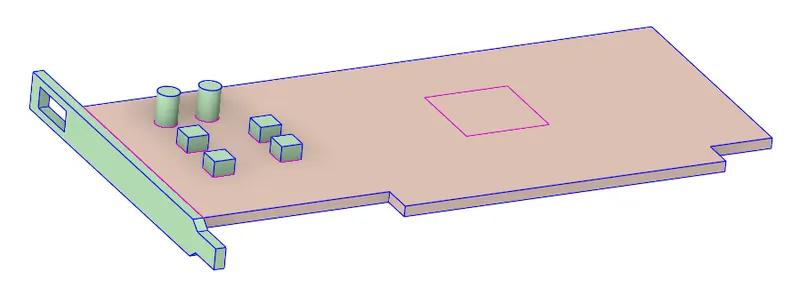
Geometry of Graphics Card's Processor
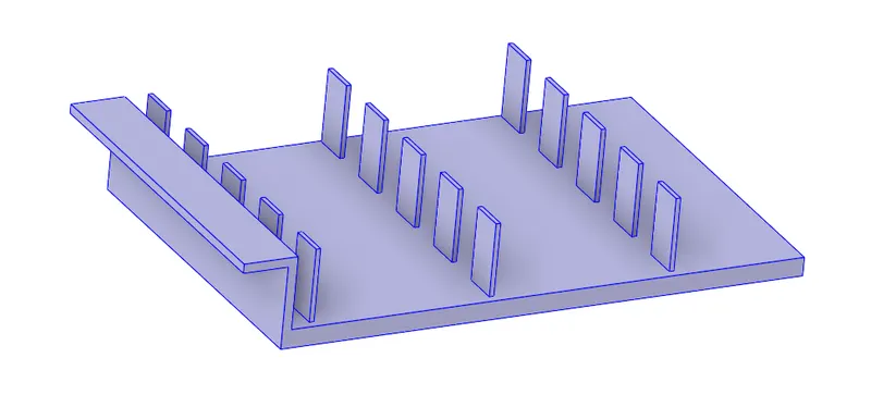
Geometry of Graphics Card's Fins
Geometry of Graphics Card's Enclosed Assembly
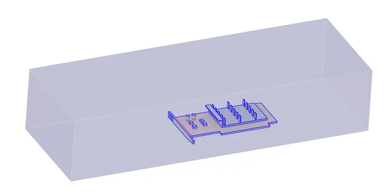
- After importing the graphics card geometry, made the shared topology between fluid volume and solid volume for getting the conformal mesh.
Meshing
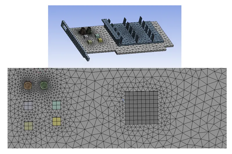
- We start the mesh by naming the parts
- Inlet, outlet, Wall symmetry.
- Then we give a total element size of 1.75 mm and applying a body sizing to the components with an element size of 1 mm to make the mesh refined.
Fluent Solver
- Solver type - Pressure-Based
- Energy - On
- Viscous - SST-k-omega ( It was selected because the equation of k-omega predicts the flow near the wall (viscous sub-layer) better than the k-epsilon model).
- Materials:
| Density | Specific Heat | Thermal Conductivity | ||
| Fluid | Air | 1.225 | 1006.43 | 0.0242 |
| Aluminium | 2719 | 871 | 202.4 | |
| Solid | FR-4 | 1850 | 1150 | 0.2728 |
| Silicon | 2329 | 700 | 148 |
Solution Setup
- Inlet velocity - 5m/s and Temperature - 300 K
- Set the heat generation source term on processor as `156250000 W/m^3`
- Heat generation was calculated as by assuming graphics card desipates energy in the form of heat as 10W and volume of the card as `64mm^3` `(8\times 8\times 1\ mm^3)`, So, the heat generated = `P/V=10/{64*10^-9}=156250000W/m^3`
- Method of solve - Coupled
- Create reports/plots for the average temperature on base plate, processor and fins
- Initialization - Hybrid
Results
Grid Indipendence Test
- Based on the examination of various grid conditions, the grid independence test is a procedure used to identify the best grid condition that has the fewest grids possible without producing a difference in the numerical results.So, fro the given geomentry the grid indipendencet test has been conducted for 1 m/s.
| No of Grids \ No of Mesh elements | Average temperature of Processor (°C) | Average temperature of Fins (°C) | Average temperature of Base Solid (°C) |
| 83546 (Base Line Mesh) | 303.603 | 297.638 | 108.373 |
| 226291 | 313.826 | 308.891 | 115.367 |
| 561209 | 317.124 | 317.124 | 118.328 |
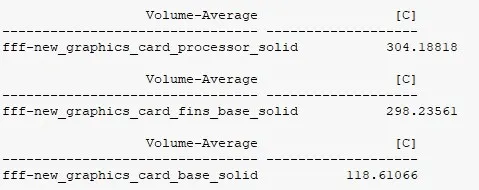
| 891280 | 304.188 | 304.188 | 118.611 |
| 1519910 | 301.436 | 301.436 | 119.148 |
| 2119152 | 299.743 | 299.743 | 118.938 |
- From the above grid indipendencet test, No of Mesh elements of 891280 was providing the results with minimal variation, so we will proceding with that mesh for further simulation.
Inlet velocity = 1m/s
Residuals and Plots
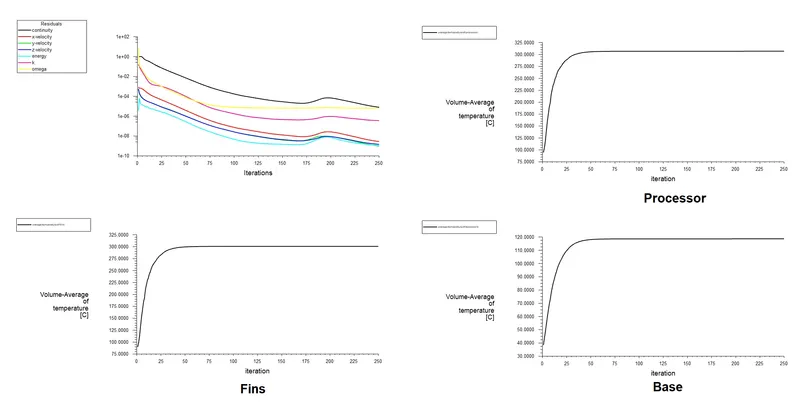
Average temperature value of processor, fins and base solid
Temperature Variation
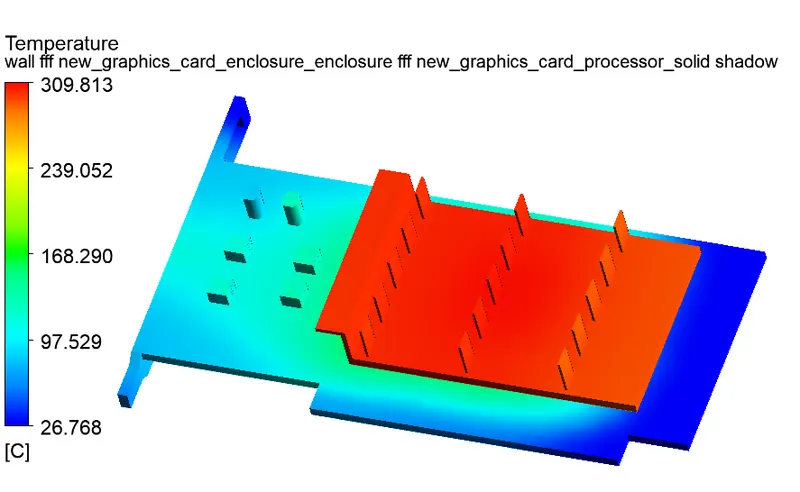
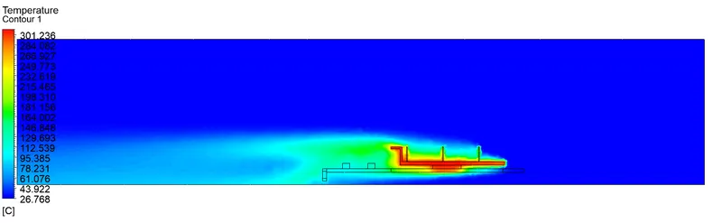
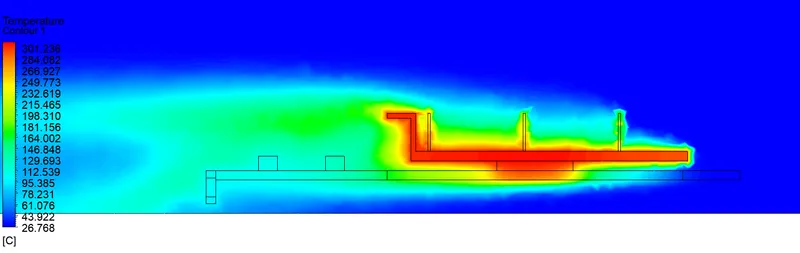
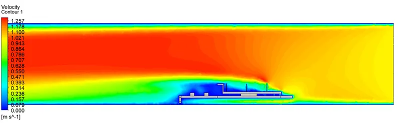
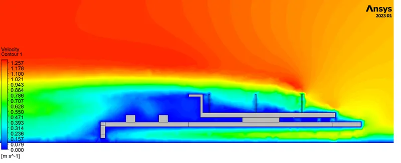
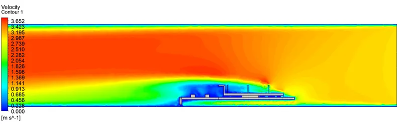
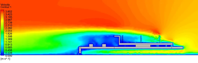
Velocity Variation
Inlet velocity = 3m/s
Residuals and Plots
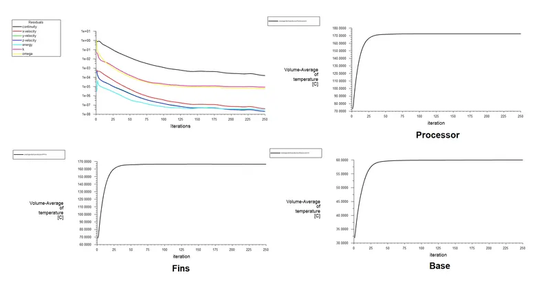
Average temperature value of processor, fins and base solid
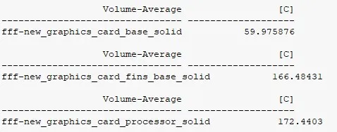
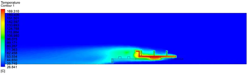
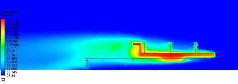
Temperature Variation
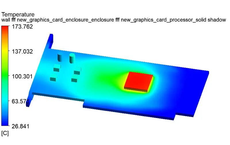
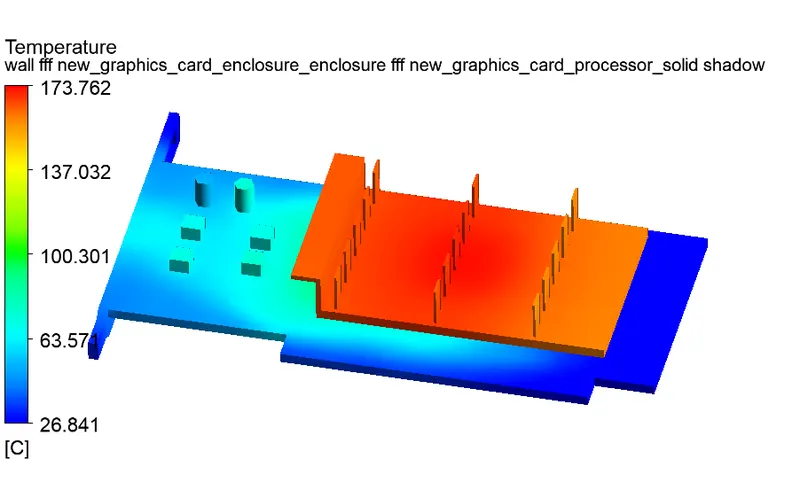
Velocity Variation
Inlet velocity = 5m/s
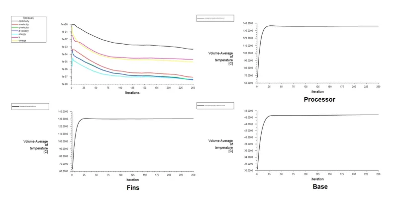
Residuals and Plots
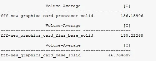
Average temperature value of processor, fins and base solid
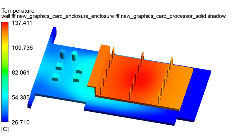
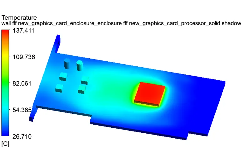
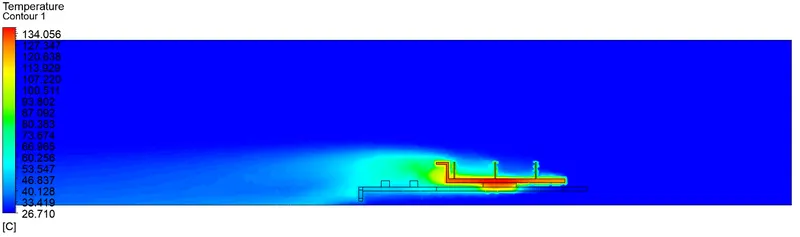
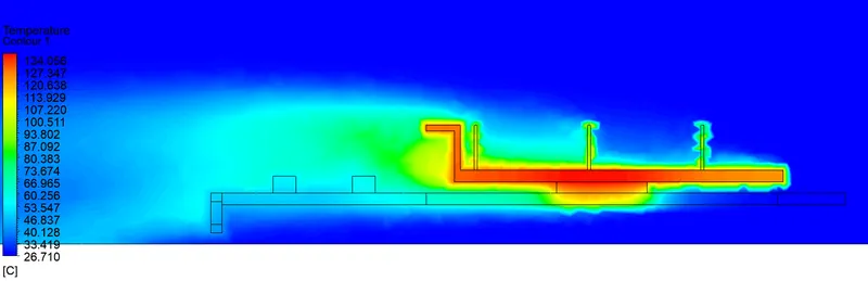
Temperature Variation
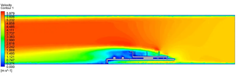
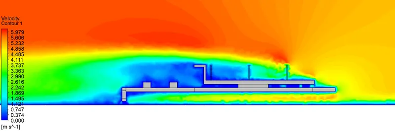
Velocity Variation
|
Velocity (m/s) |
Maximum Temperature of Processor (K) | Wall Heat Transfer Coefficient `(W//m^2K)` |
| 1 | 582.909 | 548.967 |
| 3 | 446.825 | 550.479 |
| 5 | 410.437 | 554.518 |
Conclusion
- Repetitive plots in the Residual plot revealed a converged solution for the input sets that were provided. The procesor served as a heat input source, making it one of the study's hotspots.
- We observed a significant decrease in temperature with increasing velocity and a significant increase in heat transfer coefficient, demonstrating that high-velocity air can be a useful method of heat dissipation in graphics cards.
- Hotspots may be seen in the fin and base close to the processor-facing surface based on the temperature distribution. The temperature is divided among the component in accordance with the material's thermal conductivity. Our observation of a few high-temperature regions on fins far from the processor shows their great vulnerability to heat as a result of their shape.
- Additionally, there is a significant difference between baseline and refined mesh, leading us to the conclusion that more refined mesh offers a superior solution and may be utilised to optimise the design for these applications.The change in the gradients is quite slight, and this leads us to believe that the solution has converged based on the residual plot.