Week 3 Challenge : CFD meshing on Turbocharger
CFD MESHING ON TURBOCHARGER
Aim:
To create a volumetric meshing for the Turbocharger model using ANSA.
Objective:
To create a volumetric meshing for the Turbocharger model using ANSA, for the CFD analysis with different mesh target length for different components with mesh element type of Tetra CFD.
Introduction:
ANSA is a comprehensive CAE pre-processing software for finite element analysis that delivers all of the flexibility needed for complete model build up, from CAD data to solver input file, in a single unified environment.
Mesh generation is the process of defining continuous geometric forms such as 3D models by employing 1D, 2D, and 3D mesh face shapes by means of discretization. The finer the mesh, the more precisely the 3D model is specified.
A surface mesh is a collection of polygonal faces, commonly triangle (Tria), that collectively create the object's surface covering. A surface mesh has the benefit of being quick to produce and useful for visualisation.
Volumetric meshes are polygonal representations of an object's inner volume used in 3D computer graphics and modelling. Volumetric meshes additionally discretize the item's internal structure, in contrast to polygon meshes, which solely represent the surface of an object as polygons.
Steps:
- Import the CAD geometry
- Clean up the geometry by TOPO deck
- Apply the mesh conditions using mesh deck
- Generate the surface mesh
- Detect the volumes
- Delete the unwanted volumes
- Generate the volumetric mesh for the required volumes.
Procedure:
- Open the CAD geometry by importing the CAD model file which having the extension of .ansa which can be seen in Fig.1.
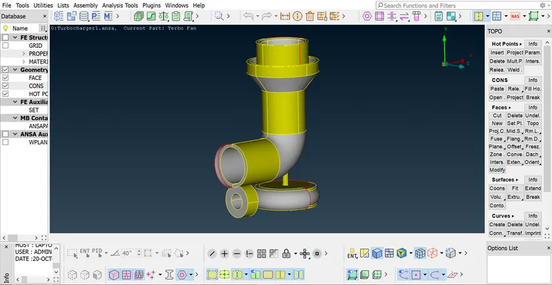
Figure 1
- As we can see there are many openings in surface of the turbocharger model, it will give geometry error as we can see in Fig. 2. So, we have to patch or fill the missing surfaces by using tools like cut, fill hole in TOPO deck.
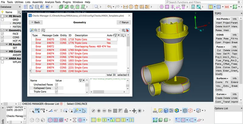
Figure 2
- From Fig.3, we can see that geometry error has been shown to be resolved by creating the required surfaces or by modifying the existing surfaces by using tools like cut, fill hole in TOPO deck.
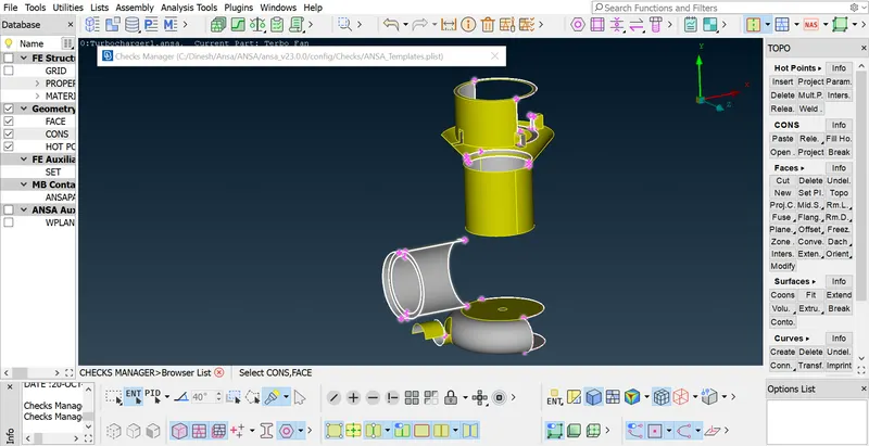
Figure 3
- From Fig.4, we can see that the geometry error has been resolved by creating the required surfaces or by modifying the existing surfaces by using tools like cut, fill hole in TOPO deck. From Fig.4, it was evident that all the open ports were closed as well to complete the geometry profile.
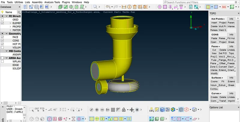
Figure 4
- Before going for meshing, assign the PID region for the common set of surfaces based on the different components in the model. PID regions has been assigned which can be seen in Fig. 5
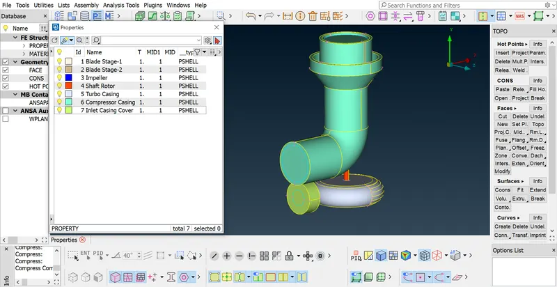
Figure 5
- After assigning PID region, check the geometry for any existing error before going to meshing. Geometry check has been done which can be seen in Fig.6, which shows the Triple Cons error, but all the times Triple Cons error was not an actual error. So, moving the geometry further from TOPO Deck to MESH Deck for meshing.
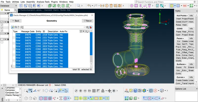
Figure 6
- To perform surface mesh with the given mesh target lengths as per PIDs are
- Blade stage-1 = 1 mm
- Blade stage-2 = 1 mm
- Impeller = 2 mm
- Shaft rotor = 1 mm
- Turbo casing = 5 mm
- Compressor casing = 5 mm
- Inlet casing cover = 5 mm
- Then in mesh generation tab using spot mesh tool create the triangular (Tria) mesh on the surface of turbocharger model. From the Fig. 7, we can see that the surface of the turbocharger was meshed and the mesh’s were in triangular (Tria) element and there is no quads element which can be evident in the details panel which is located in the side bottom of the interface. Now the model was ready for the volumetric meshing.
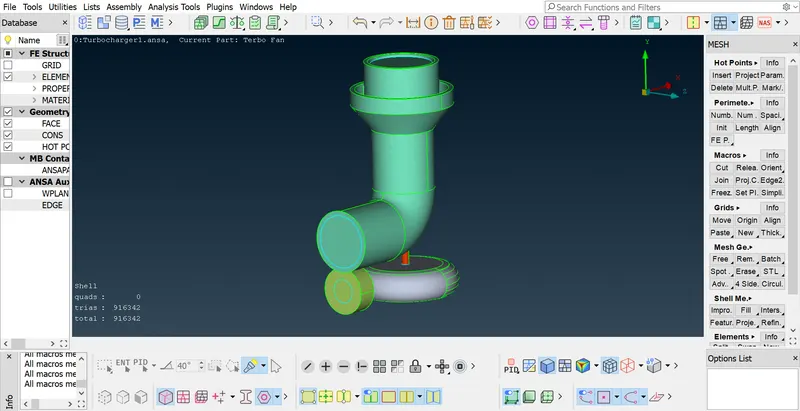
Figure 7
- In the volumetric mesh deck, by using define option, auto detect the available volumes for the whole data base which can be seen in Fig. 8. Then delete the unwanted volumes.
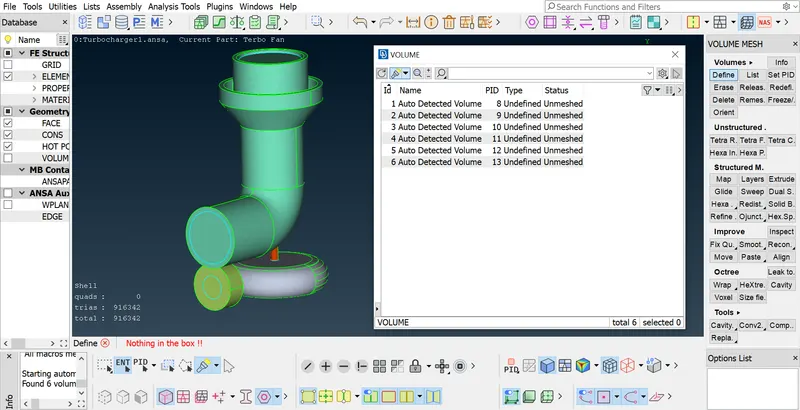
Figure 8
- By setting the volumetric mesh element type of Tetra CFD, mesh the required volumes to be meshed. The given model has been volumetric meshed with Tetra CFD which can bee seen in Fig.9 and the cross sectional view of the given turbocharger model’s volumetric mesh can be seen in Fig.10.
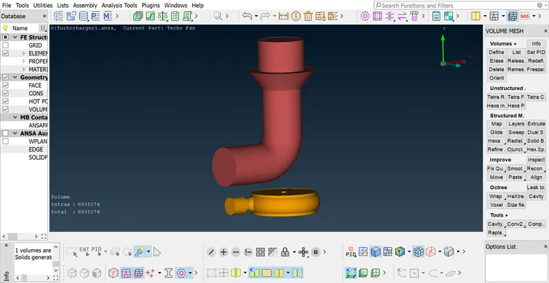
Figure 9
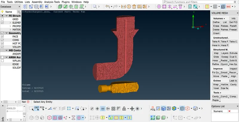
Figure 10
Learning outcome:
I learnt how to fix geometry and surface mesh flaws to generate the volumetric mesh for turbocharger model, as well as how to remedy mesh errors and how to correct such mistakes.
Conclusion:
Volumetric mesh had been done for the turbocharger model by doing the TOPO clean-up with no geometry error with a different mesh length for different components and having the volumetric mesh element of Tetra CFD which yields a number of mesh elements of 6935374.
File Link: https://drive.google.com/file/d/1ElBsHe3oIKgqSB7Bq85LFuNZVtBMu2M_/view?usp=share_link