Week 6 - CHT Analysis on a Graphics card
AIM
To perform a steady-state conjugate heat transfer analysis on a model of a graphics card.
OBJECTIVES
- Run the simulation by varying the velocity from 1m/sec to 5m/sec for at least 3 velocities and discuss the results.
- Find out the maximum temperature and heat transfer coefficient attained by the processor.
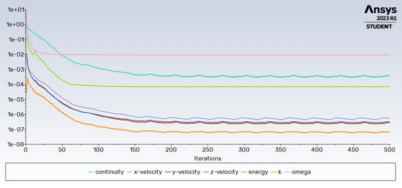
- Prove that the simulation has achieved convergence with appropriate images and plots.
- Identify potential hotspots on the model.
THEORY
Conjugate Heat Transfer (CHT) Analysis
Conjugate heat transfer in Computational Fluid Dynamics (CFD) refers to the simulation and analysis of heat transfer phenomena that occur simultaneously in both solid and fluid domains. It involves the interaction between fluid flow and heat transfer across solid boundaries.
In many engineering applications, such as cooling of electronic devices, heat exchangers, combustion chambers, and thermal management systems, the transfer of heat occurs through both the fluid medium and the solid structures. Conjugate heat transfer simulations aim to capture this coupling between the fluid and solid regions to obtain accurate predictions of temperature distribution, heat flux, and other related parameters.
Graphics Card
A graphics card, also known as a video card, GPU (Graphics Processing Unit), or graphics adapter, is a hardware component in a computer system that is specifically designed to handle and accelerate the rendering of visual data, primarily for displaying images, videos, and 3D graphics on a monitor or display device.
METHOD/PROCEDURE
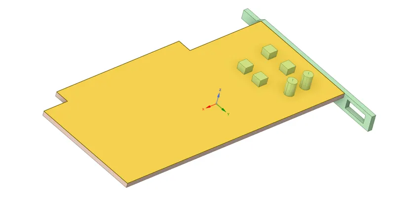
- Geometry
At first, the geometry was imported to SpaceClaim.
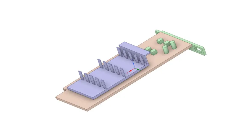
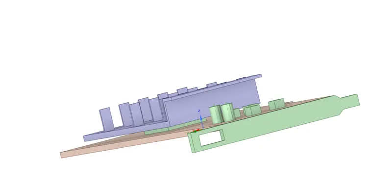
Parts of the Solid domain
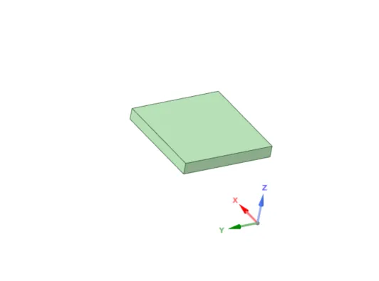
- Processor
- Fins
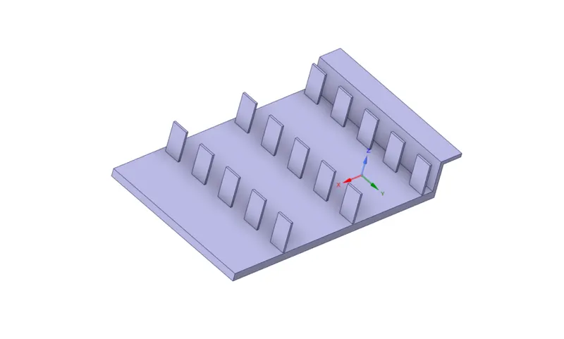
- Base
- Fluid Domain enclosing the Grahics Card
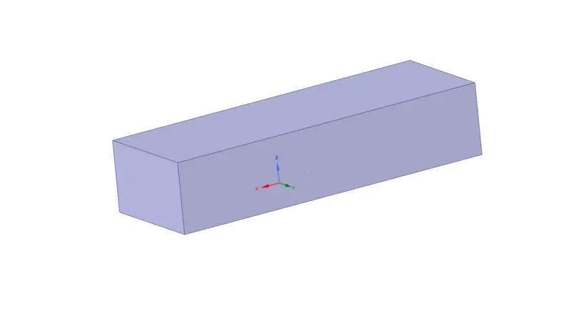
The share topology feature was enabled as it allows multiple solid bodies to share common boundaries or faces. It enables the creation of a single face or edge that is connected and shared between two or more adjacent bodies, rather than having separate, duplicate faces or edges for each body.
1. BASE MESH
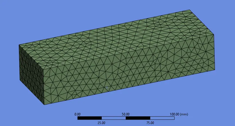
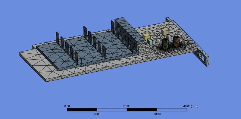
- Meshing
Initially, coarse meshing was used.
Element size = 8 mm
- Fluent setup
Pressure based solver was used.
Velocity formulation - Absolute
The energy equation was turned on.
K omega turbulence model was selected.
Materials used:
- For the Fluid domain: Air
Density = 1.225 kg/m^3
Viscosity = 1.7894e-05 kg/ms
- For Fins: Copper
Density = 8978 kg/m^3
Specific heat = 381 j/kg-k
Thermal conductivity = 387.6 w/m-k
- For Processor: Silica
Density = 2328 kg/m^3
Specific heat = 710 j/kg-k
Thermal conductivity = 150 w/m-k
- For Base: Steel
Density = 8050 kg/m^3
Specific heat = 502 j/kg-k
Thermal conductivity = 16.27 w/m-k
Cell zone conditions:
The materials were selected as shown above.
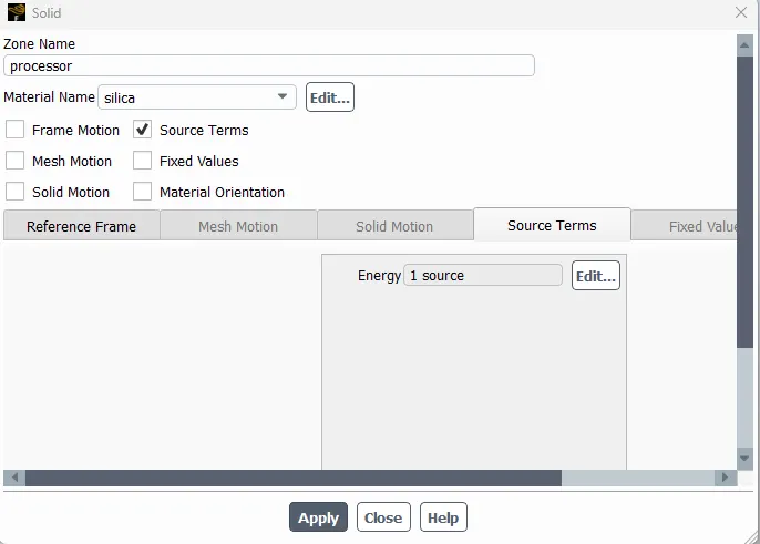
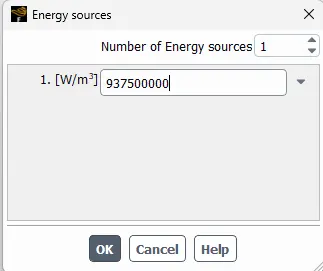
Here we assume the processor is the heat source. Therefore, the "Source Terms" are enabled in the cell zone condition and we have given the value of the number of energy source as 1.
- Calculation of the energy produced
Let us assume the processor consumes a power of 60 W.
The volume of the processor is given by 8*8*1 mm^3
Therefore, the energy produced = Power/Volume = 60/6.4e-8 = 937500000 W/m^3
Boundry Conditions
Inlet velocity = 1m/s
Inlet temp = 300 k
Outlet Gauge pressure = 0 pa
Initialization
After initialization, the necessary contour plots are added
Run Calculation
The solution is calculated for 500 iterations.
- Results
Base mesh used
Inlet velocity used 1 m/s
Residual Plot
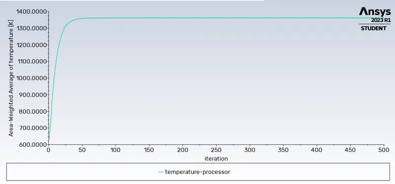
The temperature at the processor
Temperature Contour Plot at XZ plane
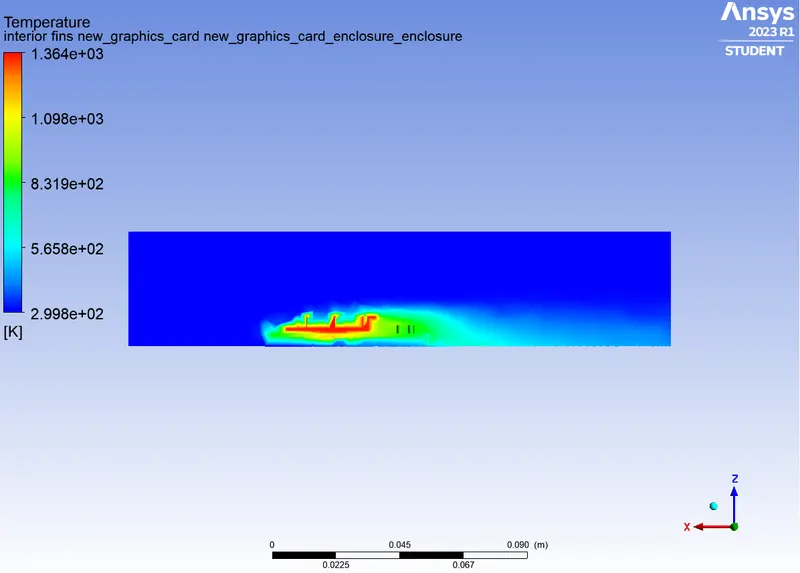
Potential Hotspot at the base under the position of the Processor
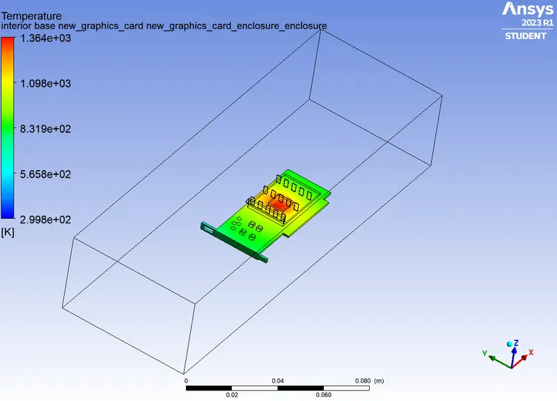
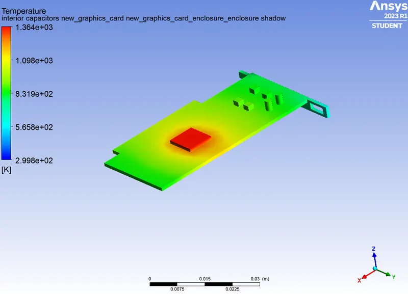
For velocity at 1m/s
Maximum Temperature attained by the processor = 1361.41 K
HTC at the processor = 444.51 W/m^2 K
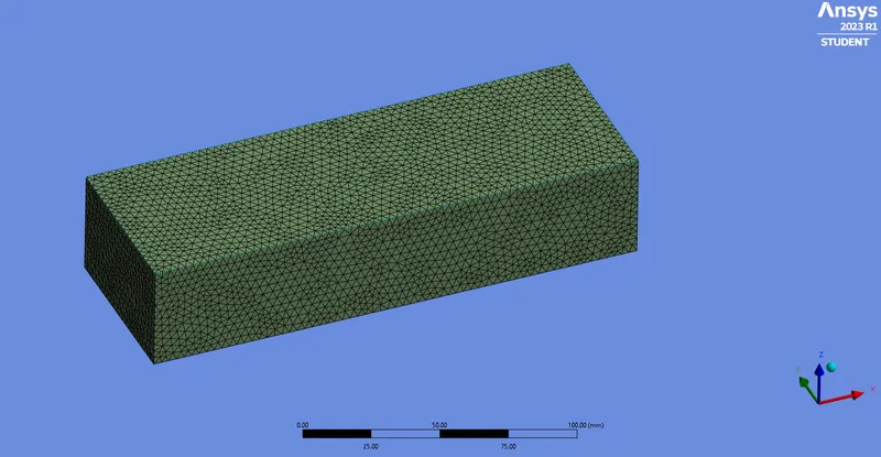
2. REFINED MESH (Inlet velocity = 3 m/s)
Element size of Fluid Domain = 3 mm
Element size of Solid Domain = 1 mm
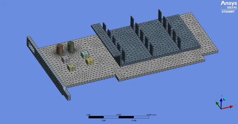
Results
For Velocity at the inlet = 3 m/s.
Residual plot
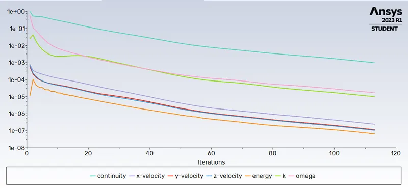
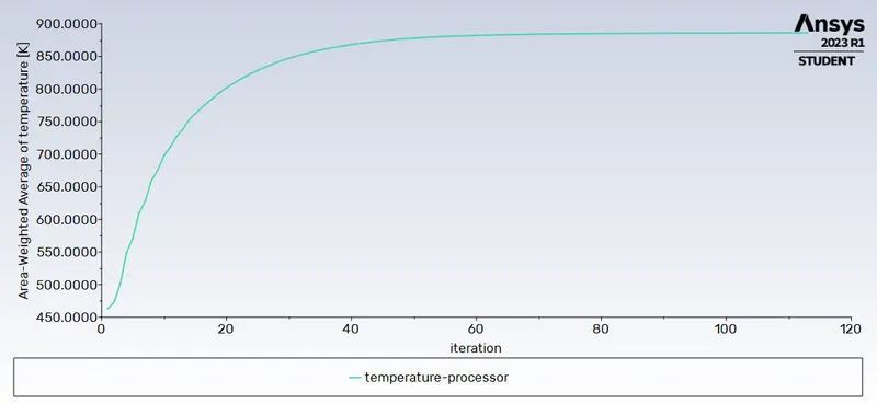
The temperature at the processor
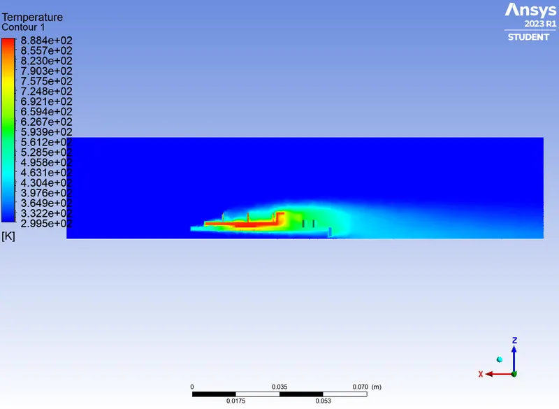
Temperature contour plot at XZ plane
Potential hot spot at the base under the position of the processor
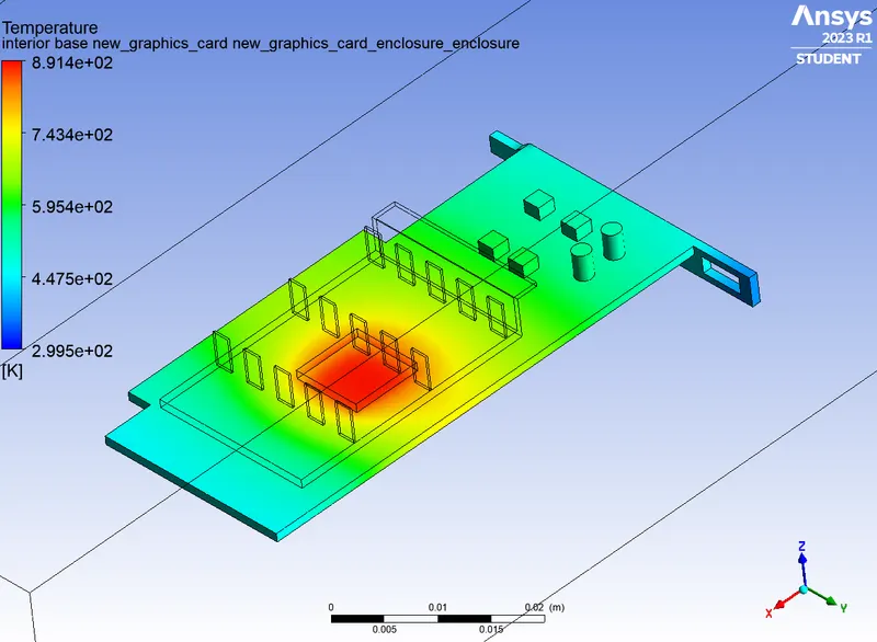
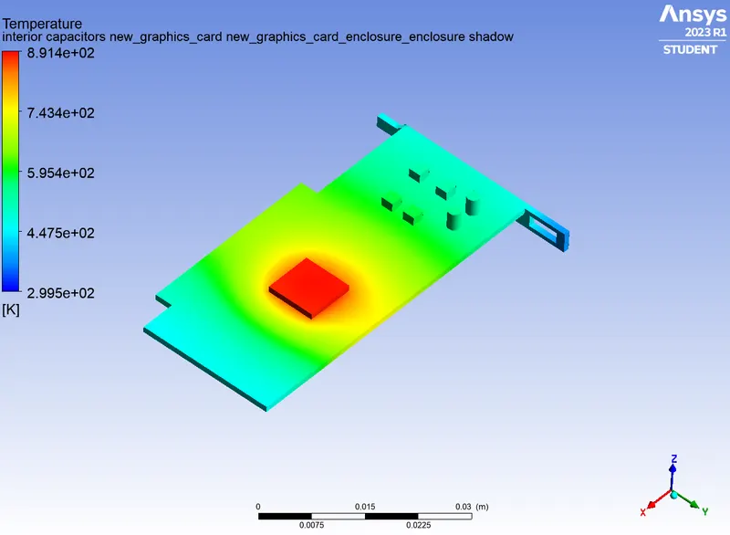
For velocity at 3 m/s
Maximum Temperature attained by the processor = 886.131 K
HTC at the processor = 635 W/m^2 K
3. REFINED MESH (Velocity at inlet = 5 m/s)
(same mesh size as the previous case was used)
Element size of Fluid Domain = 3 mm
Element size of Solid Domain = 1 mm
RESULT
For inlet velocity at 3 m/s
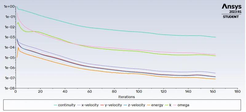
Residual plot
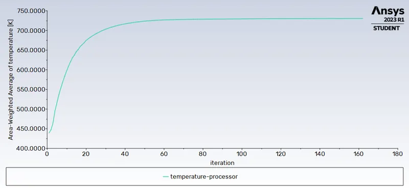
Temperature plot
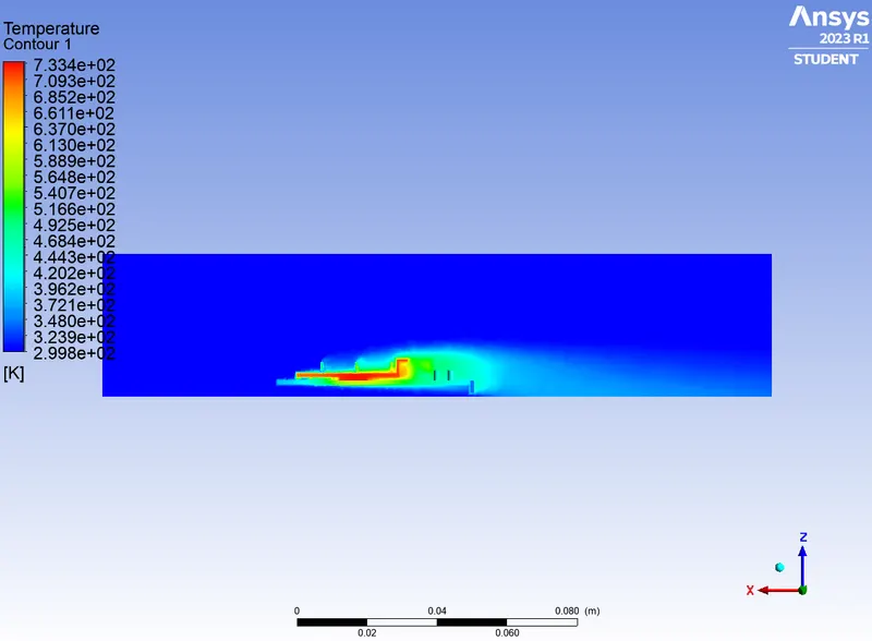
Temperature contour plot at xz plane
Potential hot spot at the base under the position of the processor
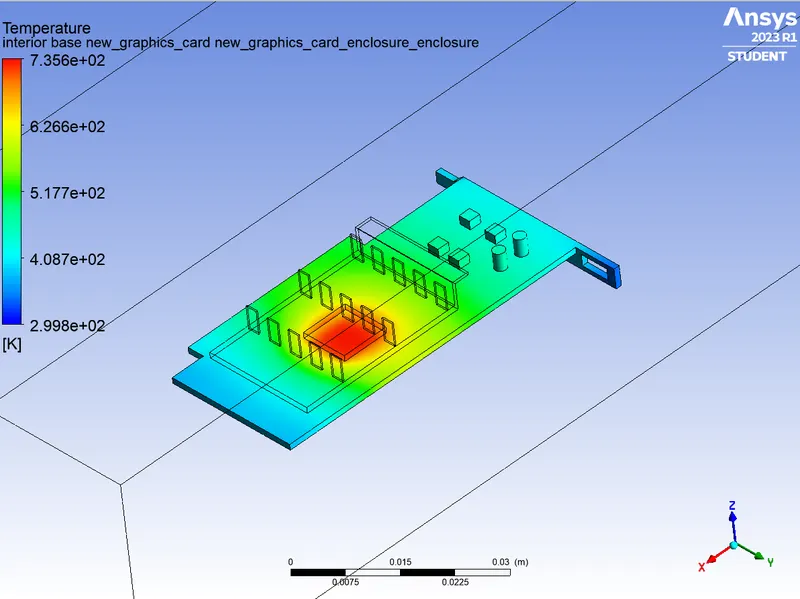
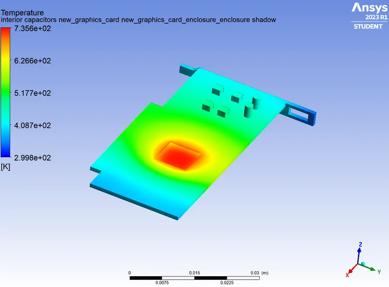
Maximum Temperature attained by the processor = 730.51 K
HTC at the processor = 806.6 W/m^2 K
Conclusion
| Base mesh -1m/s | Refined mesh - 3 m/s |
Refined mesh - 5m/s | ||
| Max temperature Processor (K) | 1361.4 | 886.1 | 730.51 | |
| Wall Heat transfer coefficient processor (W/m2K) | 444.51 | 635 | 806.6 |
- The first simulation with base mesh was having difficulty converging, it is expected that this behaviour is due to the coarse mesh and poor mesh quality. In the simulations with refined mesh, the simulation converged within 170 iterations.
- From the above table, it is clear that the net temperature of the processor of graphics cards decreases with an increase in inlet velocity. Hence it can be inferred that a higher inlet velocity results in better cooling and lower the average temperature thus keeping the components safe from damage.