Week 6 - CHT Analysis on a Graphics card
CHT ANALYSIS ON GRAPHICS CARD
Conjugate Heat Transfer (CHT) analysis of a graphics card involves studying the thermal behavior and heat transfer mechanisms within the graphics card assembly. This analysis considers both the solid components of the card as well as the fluid flow and heat transfer in the surrounding air or cooling system.
The CHT analysis of a graphics card is important for several reasons:
-
Heat Dissipation: Graphics cards generate a significant amount of heat during operation, which needs to be efficiently dissipated to prevent overheating. CHT analysis helps in understanding how heat is transferred from the various components of the graphics card to the surrounding environment or cooling system.
-
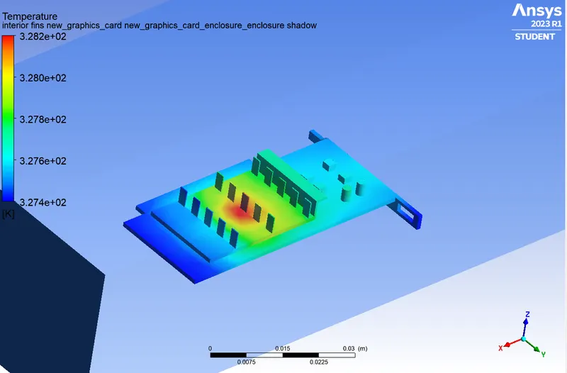
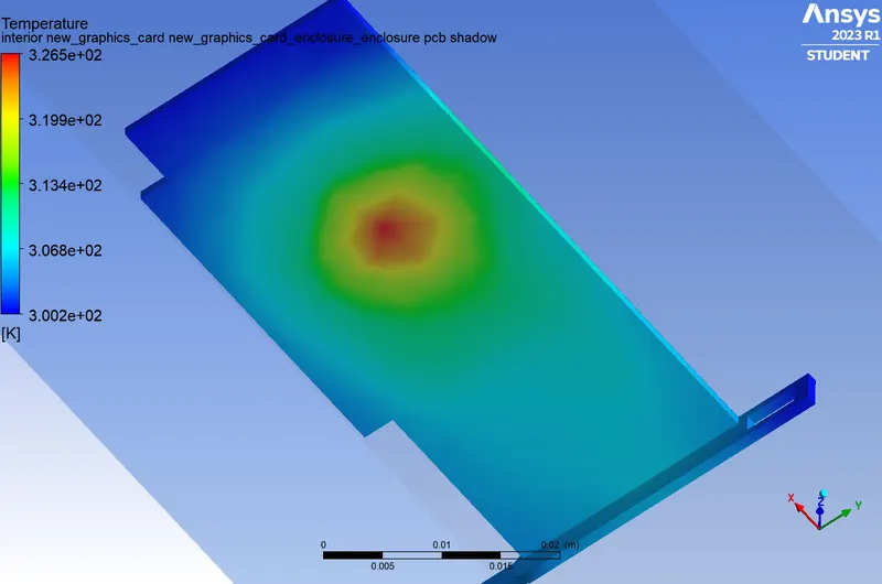
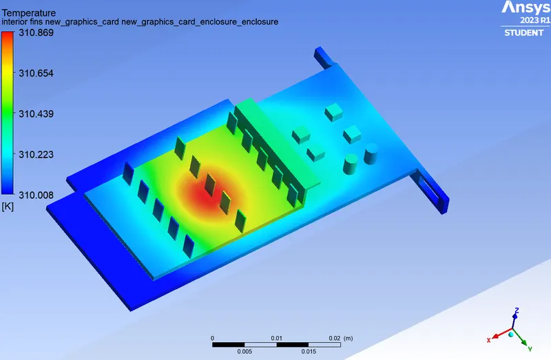
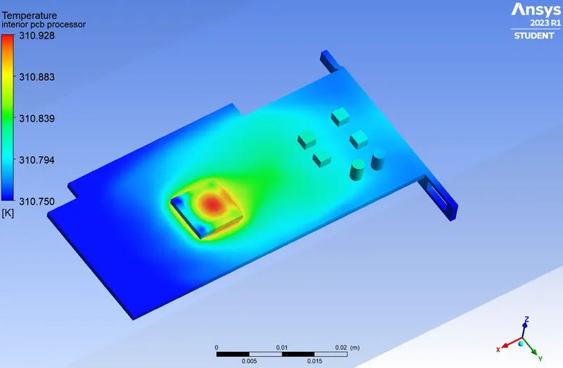
Hotspot Identification: CHT analysis helps in identifying hotspots within the graphics card assembly where temperatures are higher than desired. By pinpointing these hotspots, engineers can focus on improving the thermal design in those specific areas to prevent thermal bottlenecks and potential performance degradation.
-
Reliability and Longevity: CHT analysis helps in ensuring that the graphics card operates within safe temperature limits, thereby improving its overall reliability and longevity.
- Thermal Management Solutions: CHT analysis provides insights into the effectiveness of different thermal management solutions for graphics cards.
SIMULATION
The model is opened in ANSYS SpaceClaim.
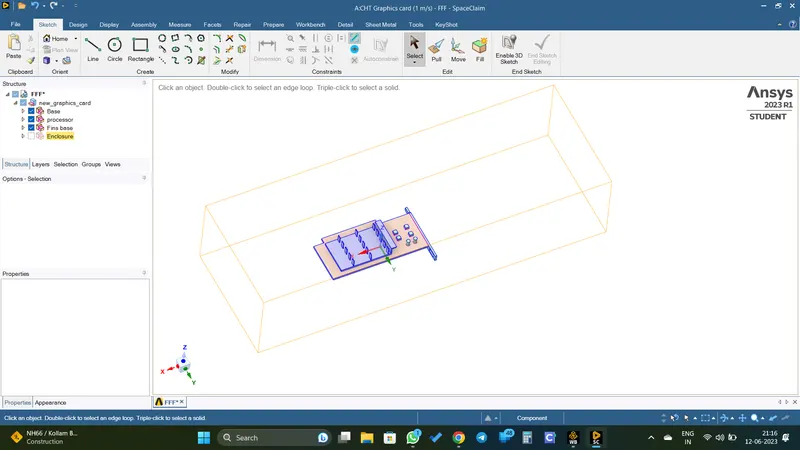
The share topology is enabled.
Then done the meshing (base mesh)
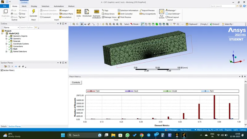
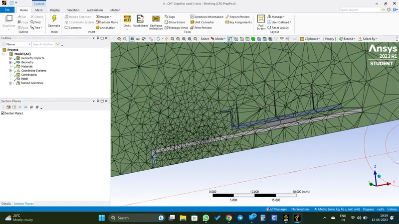
Then the meshed model is opened in ANSYS Fluent.
Simulation Setup
Solver type: Pressure based
Velocity formation: Absolute
Solver time: Steady state
Energy equation is ticked
Viscous model: k-omega STT
Material Selection
- Computational domine fluid: Air - Standard fluid
- Fins: Copper - Has a good thermal conductivity.
- Processor: Silicon - The primary material used in the fabrication of computer processors due to its excellent semiconductor properties and it also has good thermal conductivity.
- PCB: FR-4 - Commonly used for general purpose PCBs. It offers good electrical insulation properties, mechanical strength, and flame resistance.
Materials are assigned to different parts in cell zone conditions.
Inlet velocity is set to 1 `m`/`s` in the boundaty conditions.
The processor is assigned as the heat source. Here it is assumed that the power consumed by the processor is fully converted into heat, although the power consumed by a processor is not fully converted into heat, a significant portion of the power is indeed dissipated as heat.
Hence the heat dissipation can be calculated using the equation, Power/volume
Here the power is assumed as 1 `W` and the given dimensions of the processor is 8x8x1 `mm`
Then we get the heat generated is equal to 15625000 `W`/`m^3`
Created the report for the temperature of the processor and the heat transfer coefficient.
Then ran the model for 250 iteration.
RESULTS
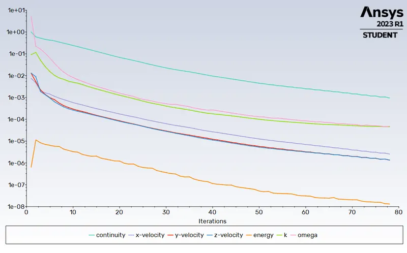
Residual Plot
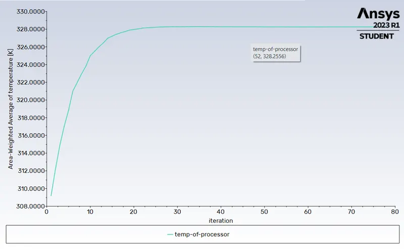
Temperature Of The Processor
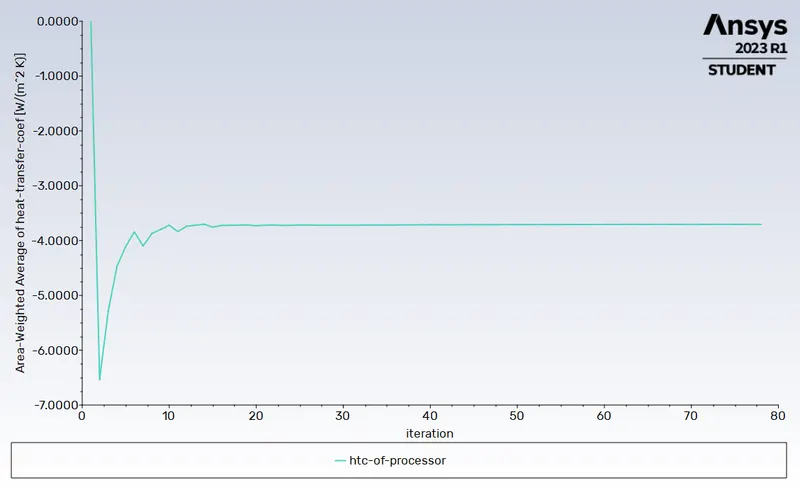
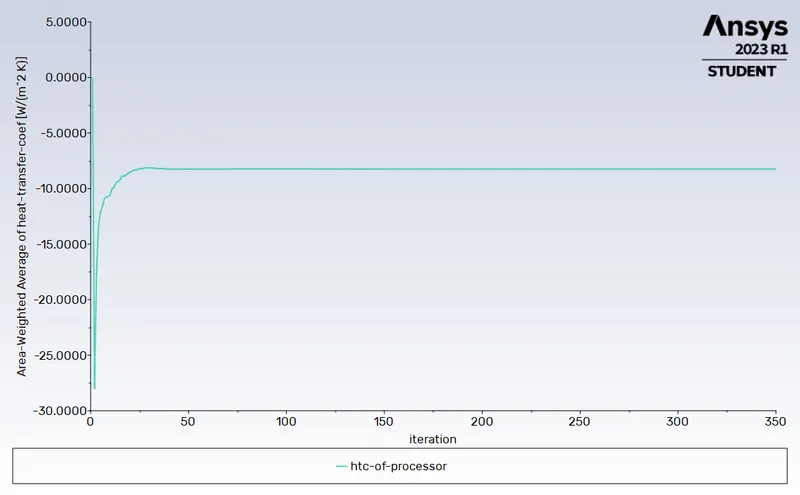
Heat Transfer Coefficient Of The Processor
Hotspot On The Fins
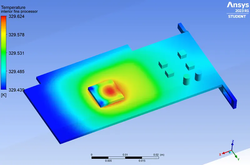
Hotspot On The Processor
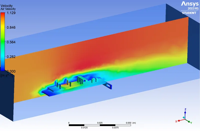
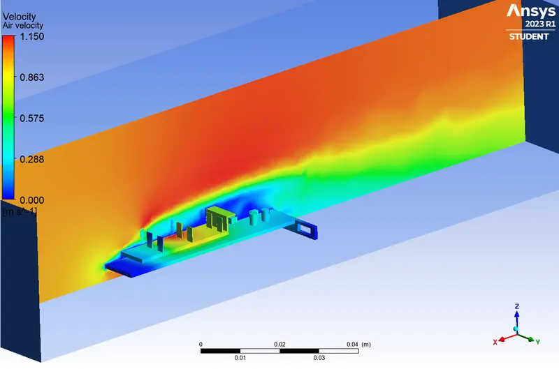
Air Velocity Contour
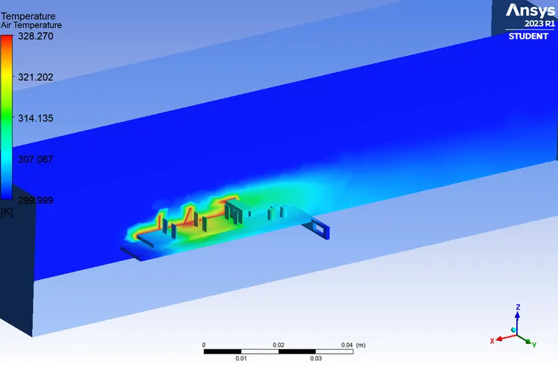
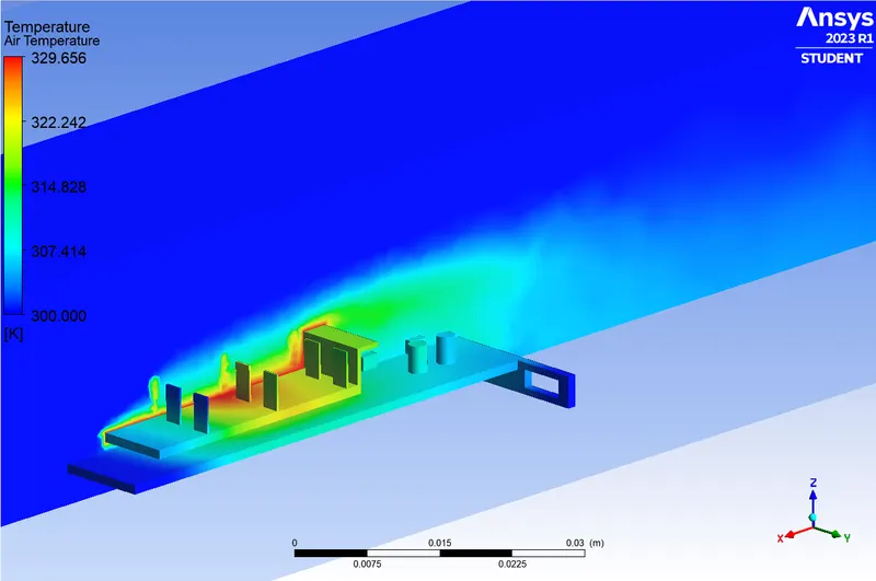
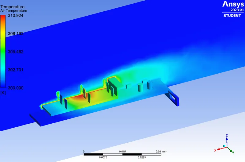
Air Temperature Contour
REFINING THE MESH
The mesh is refined using the sizing option.
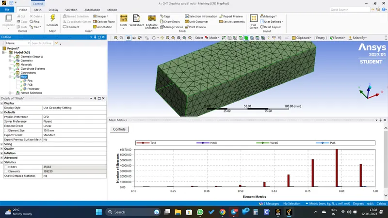
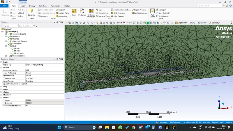
Here different element size is used for the mesh creation and hence a combination of coarse and refined mesh in different regions is achieved.
Then the model is ran again in the ANSYS Fluent with the same simulation parameters.
RESULTS
VELOCITY OF 1 m/s
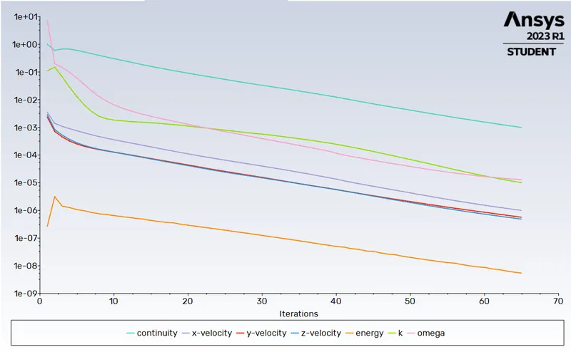
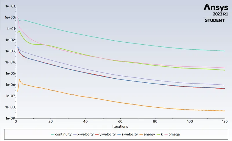
Residual Plot
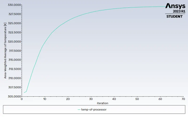
Temperature Of The Processor
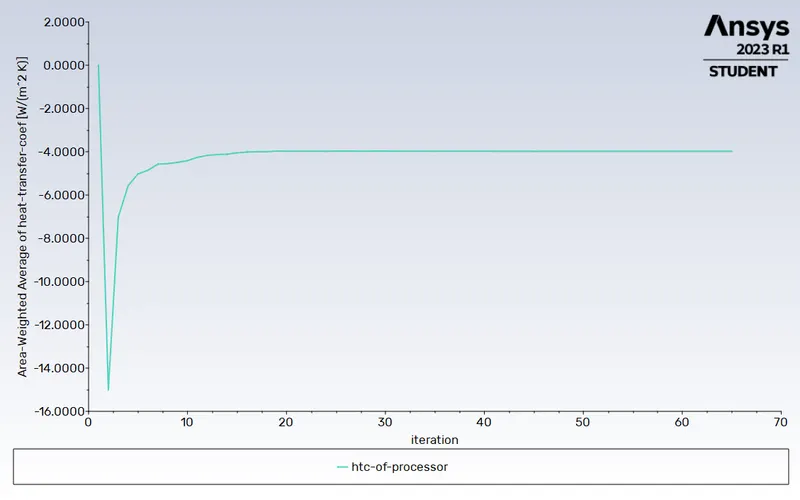
Heat Transfer Coefficient Of The Processor
Hotspot On The Fins
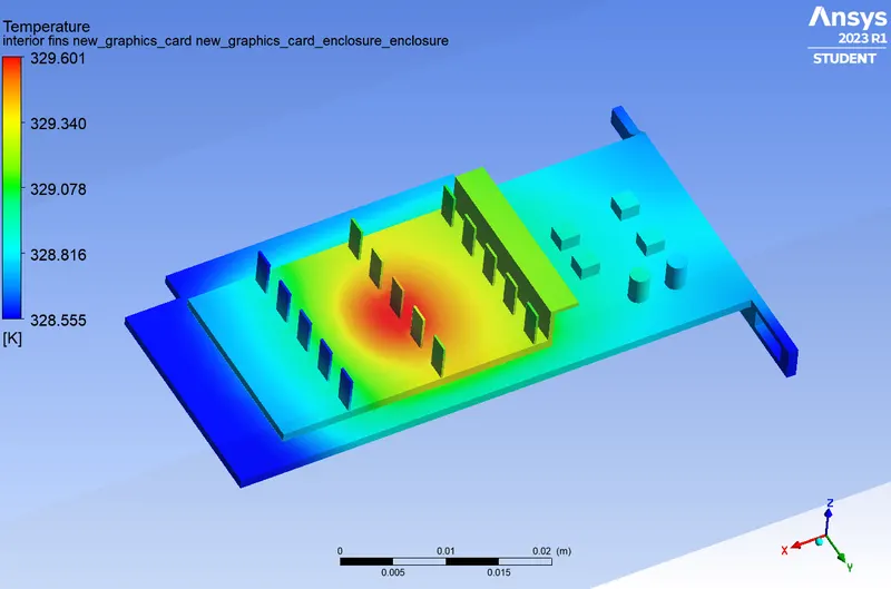
Hotspot On The Processor
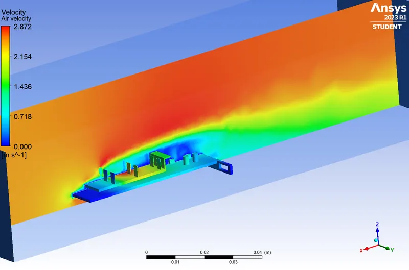
Air Velocity Contour
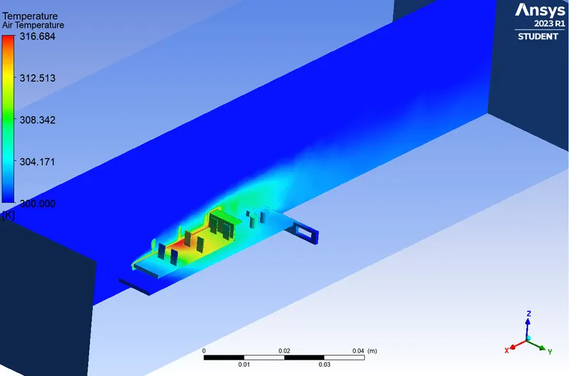
Air Temperature Contour
| Mesh Type | No: Of Elements | No: Of Nodes | Temp: Of Processor | HTC Of Processor | No: Iterations For Convergence |
| Base Mesh | 83314 | 15636 | 328.25 °C | -3.70 W/m^2 k | 78 |
| Refined Mesh | 199250 | 35683 | 329.50 °C | -3.97 W/m^2 k | 65 |
* '-' sign of the HTC indicates that the heat is liberated form the processor.
From this table we can see that the difference in temperature and difference HTC of the base meshed model and refined mesh model is almost same. Also the number of iterations for the convergence of the refined mesh is less than that of the base mesh.
So we can say the the refined mesh taken here is enough for the simulation.
NB: The computational power of the system is also considered while meshing.
Only the refined meshed model is taken for further simulation.
VELOCITY OF 2.5 m/s
Residual Plot
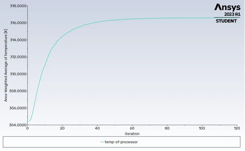
Temperature Of The Processor
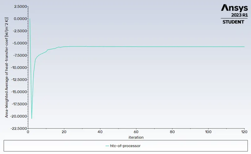
Heat Transfer Coefficient Of The Processor
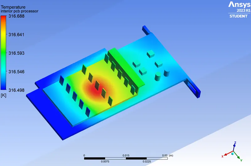
Hotspot On The Fins
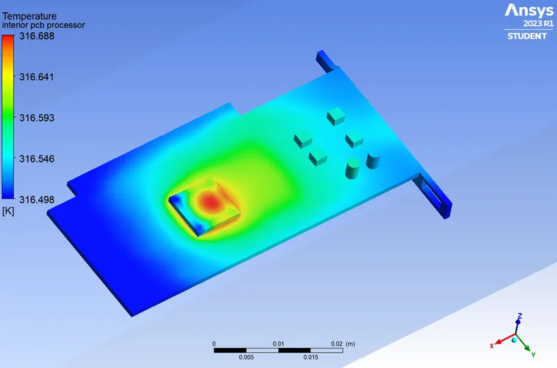
Hotspot On The Processor
Air Velocity Contour
Air Temperature Contour
VELOCITY OF 5 m/s
Residual Plot
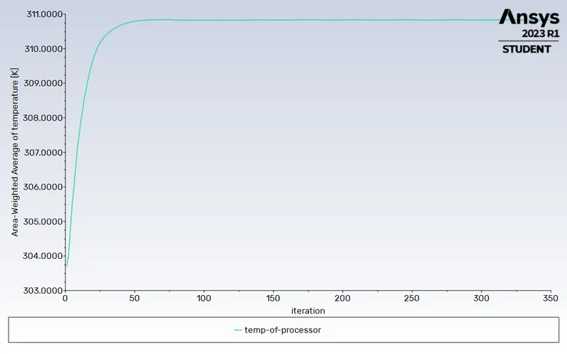
Temperature Of The Processor
Heat Transfer Coefficient Of The Processor
Hotspot On The Fins
Hotspot On The Processor
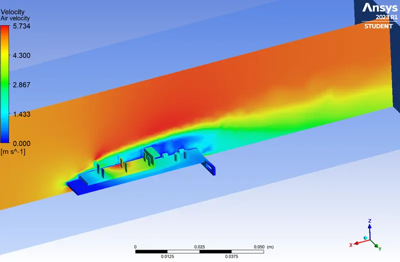
Air Velocity Contour
Air Temperature Contour
OBSERVATION
Proof For Convergence
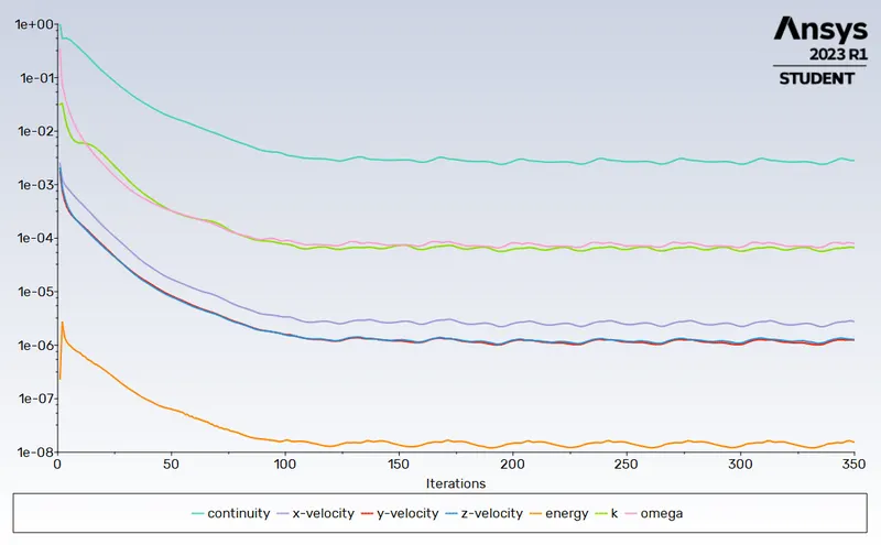
Refer the residual plots.
The residuals of the governing equations (continuity, velocity, energy, k-omega) in the simulation represent the imbalance between the computed and actual values and indicate the convergdnce of the solution. When the residuals reach a small and steady state, typically below a specified tolerance, it suggests that the solution has converged.
Here we can see that the residuals reaches a steady state, hence we can say that the solution has converged.
Table Showing The Maximum Temperature And HTC With Respect To The Air Velocities.
| Mesh Type | Air Velocity | Max: Temperature (°C) | Max: HTC (W/m^2 k) |
| Base Mesh | 1 m/s | 328.25 | -3.70 |
| Refined Mesh | 1 m/s | 329.56 | -3.97 |
| Refined Mesh | 2.5 m/s | 316.59 | -5.75 |
| Refined Mesh | 5 m/s | 310.83 | -8.24 |
INFERENCE
- From these simulation results, we can see that the velocity of the air plays an important role in cooling of the graphics card.
- Higher air velocity promotes better heat transfer between the components and the surrounding air. This is due to enhanced convective heat transfer, where the higher air flow rate helps to carry away more heat from the component's surface.
- Higher air velocity helps to reduce the boundary layer thickness around thecomponents. A thinner boundary layer results in lower thermal resistance, allowing for more efficient heat transfer from the components to the air.
- Increased air velocity reduces the residence time of air in contact with the components. This means that the air spends less time near the hot surface, reducing the chance of heat accumulation and leading to lower temperatures.
- Higher air velocity can increase the HTC due to enhanced convective heat transfer. Additionally, the presence of turbulence in the airflow can also increase the HTC by promoting better mixing and increasing the heat transfer coefficient at the surface.
For Project File, Click here