Week 6 - CHT Analysis on a Graphics card
OBJECTIVES
- Run the simulation by varying the velocity from 1m/sec to 5m/sec for at least 3 velocities and discuss the results.
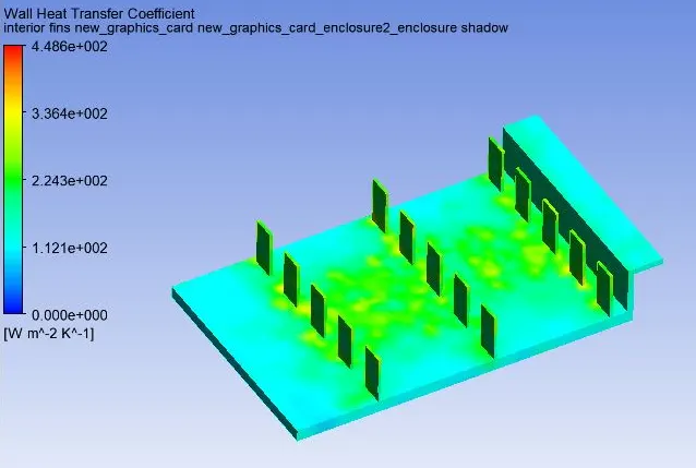
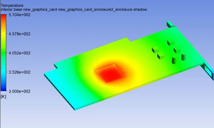
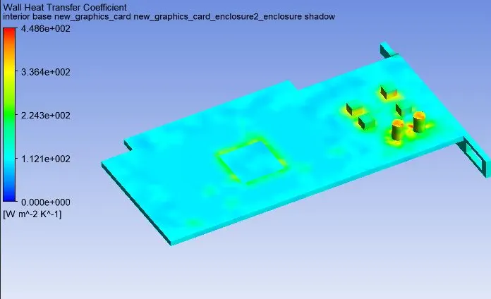
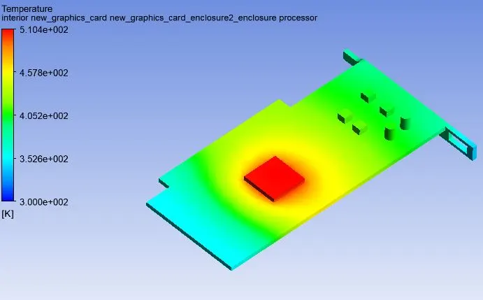
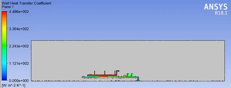
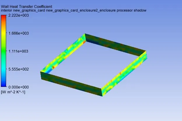
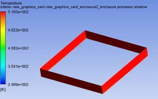
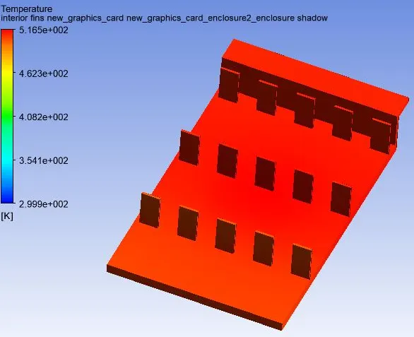
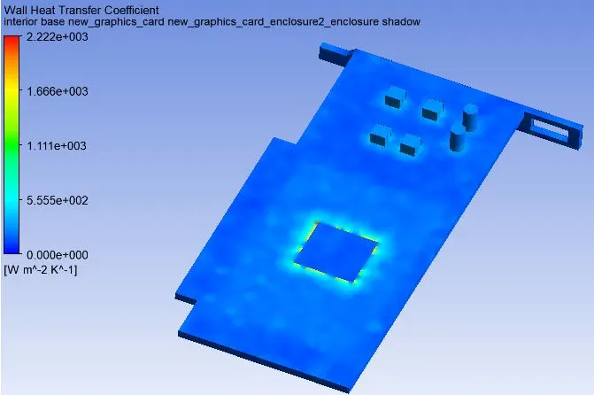
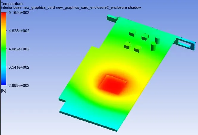
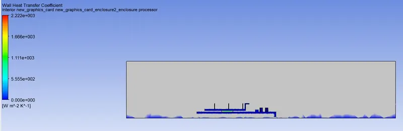
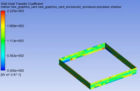
- Find out the maximum temperature and heat transfer coefficient attained by the processor.
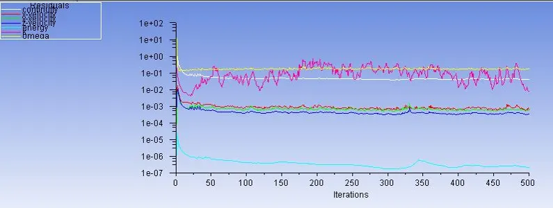
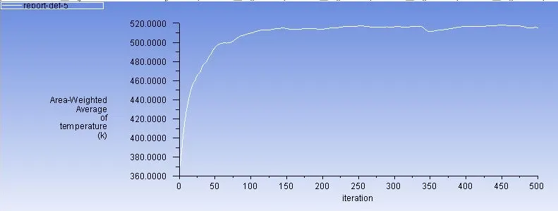
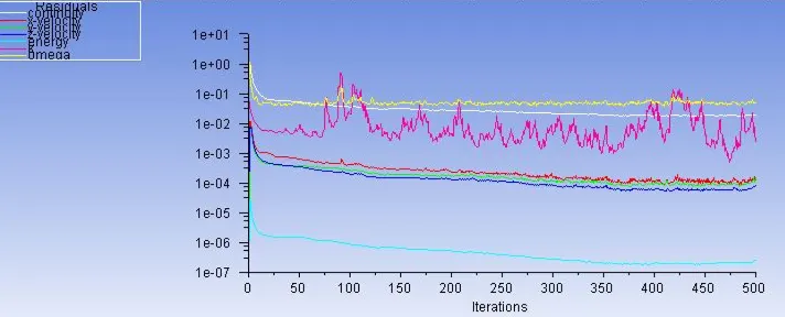
- Prove that the simulation has achieved convergence with appropriate images and plots.
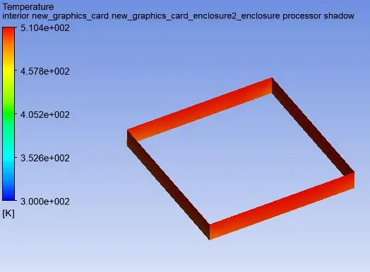
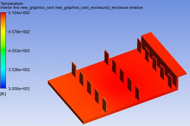
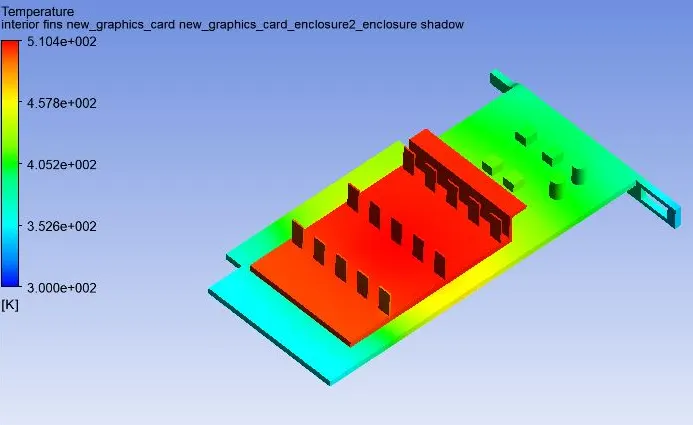
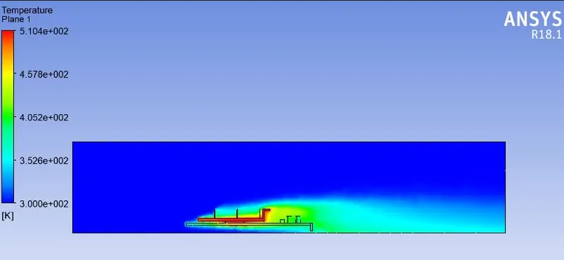
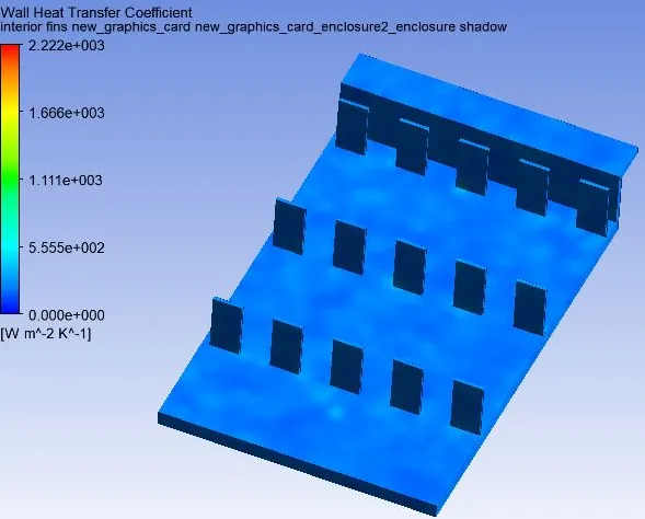
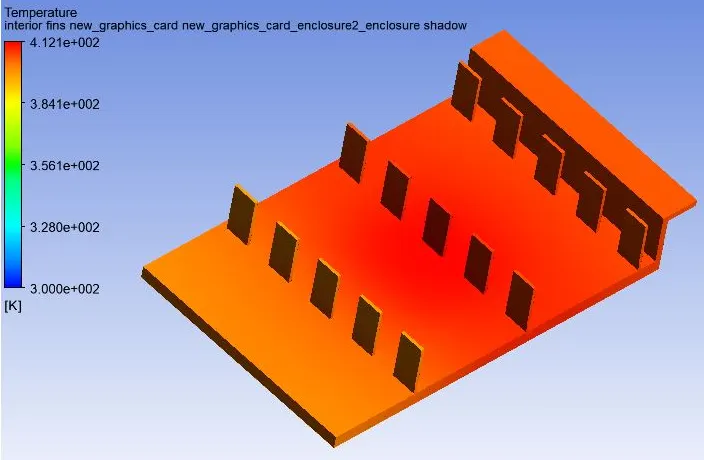
- Identify potential hotspots on the model.
Conjugate Heat transfer.
The Conjugate heat transfer analysis is based on a mathematically structured problem, whixh should describes the heat transfer problems between a body(Solid domains) and a fluid(fluid domains) which flowing over or inside it. It allows as to describe the thermal exchange of energy at the interfaces between the domains. Conjugate heat transfer analysis can accurately predict heat transfer by simultaneous solving all the relevant solid and flow field heat transfer processes. One of the simplest ways to realize conjucation is through numerical methods. The boundary conditions for the fluid and solid interfaces is set and solved through iteration methods. Conjugate heat transfer is observed in many situations for example-Conduction through solids, free and forced convection in the gases as well as fluids and also for thermal radiations.
CASE-1-Baseline Mesh.
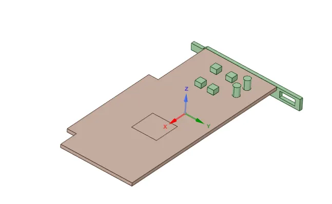
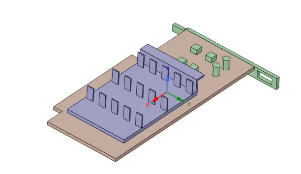
Geometry.
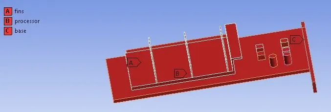
Base.
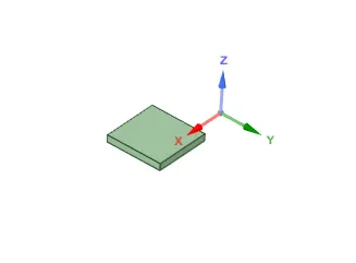
Processor.
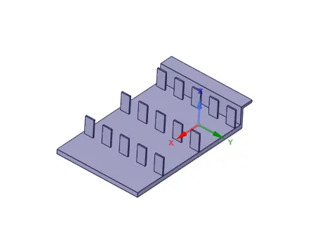
Fin Base.
Graphics Card.
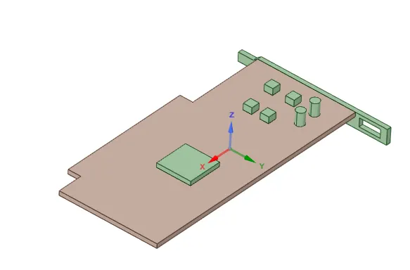
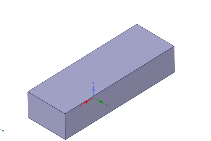
Enclosure.
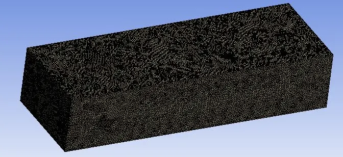
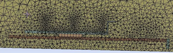
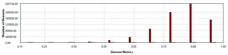
Mesh.

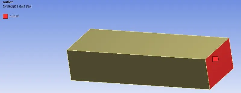
Named Selections.
Inlet. Outlet.

Graphics card.
Set up.
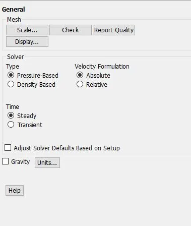
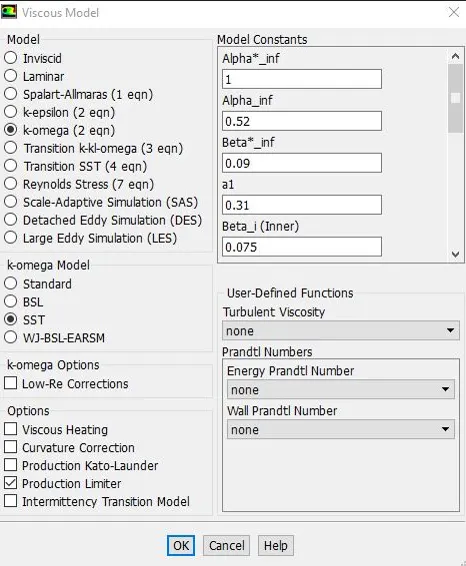
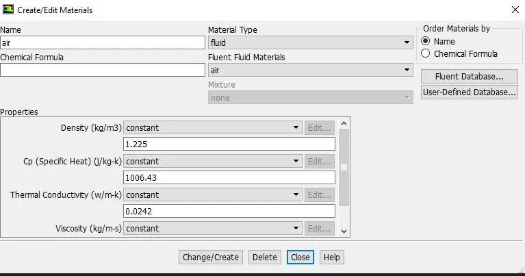
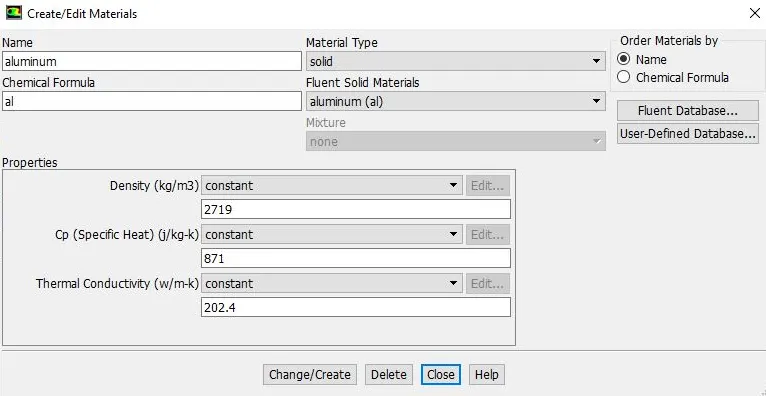
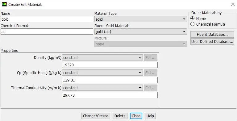
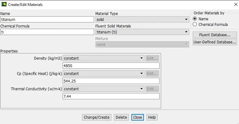
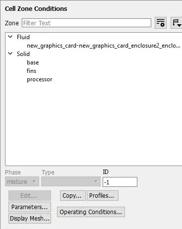
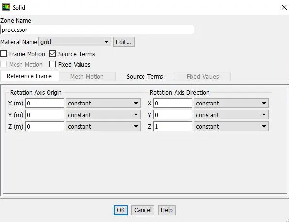
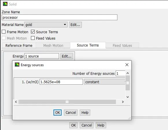
- The heat applied to the processor as Energy Sources (Source term) by considering the heat produced and volume of the processor.
- Volume of the processor=V=6.4e-08m^3.
- Graphics Card Power = P=10W.
- Energy produced by the processor= P/V= 156250000 W/M^3.
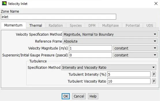
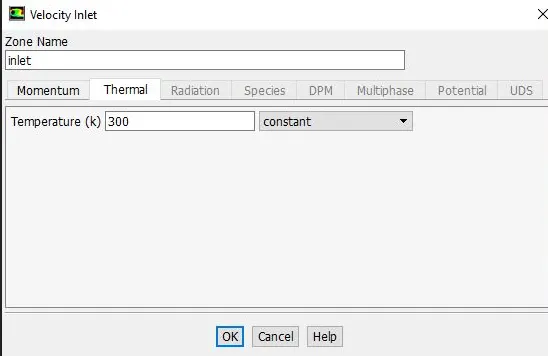
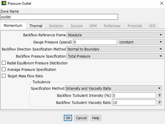
Results.
Residual.
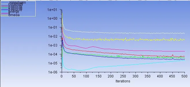
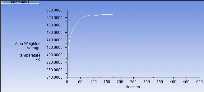
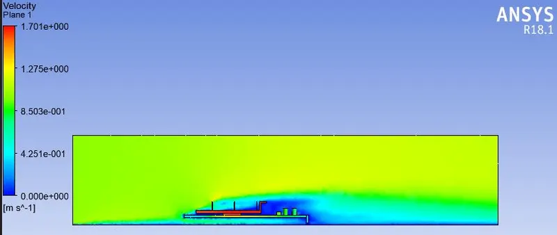
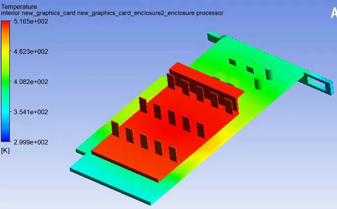
Temperature on the Graphics card.
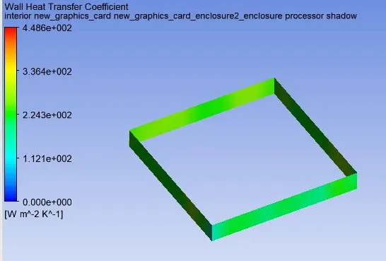
CASE-2-Refined Mesh(Velocity-1m/s).
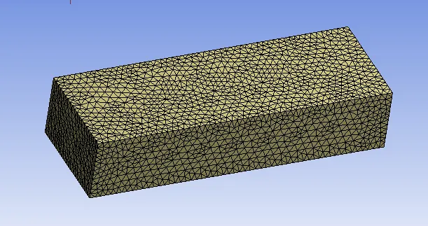
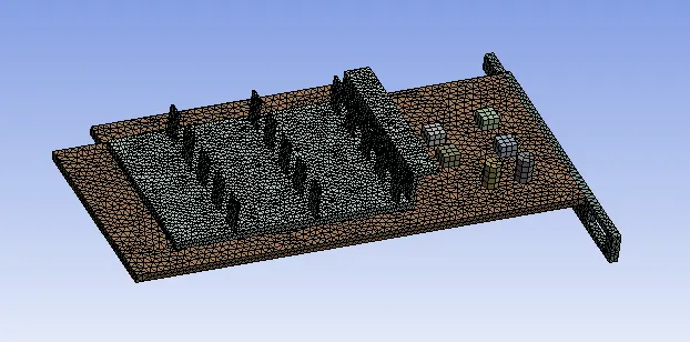
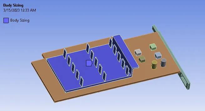
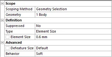
Mesh.
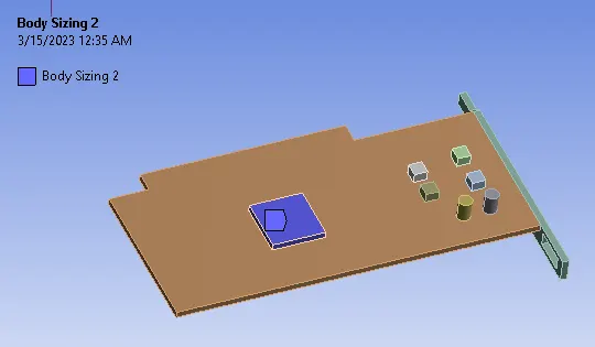
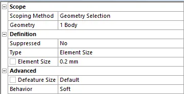
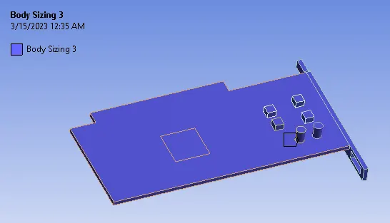
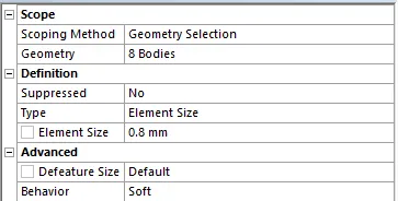
Results.
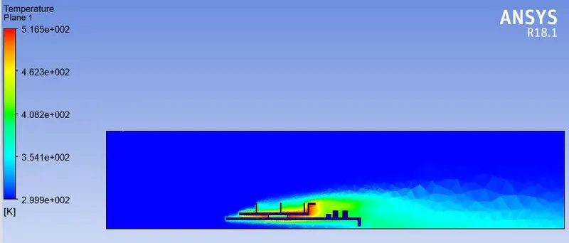
Temperature on the Graphics card.
CASE-3-Refined Mesh(Velocity-3m/s).
Results.
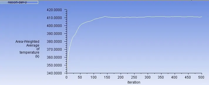
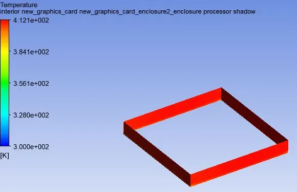
Temperature on the Graphics card.
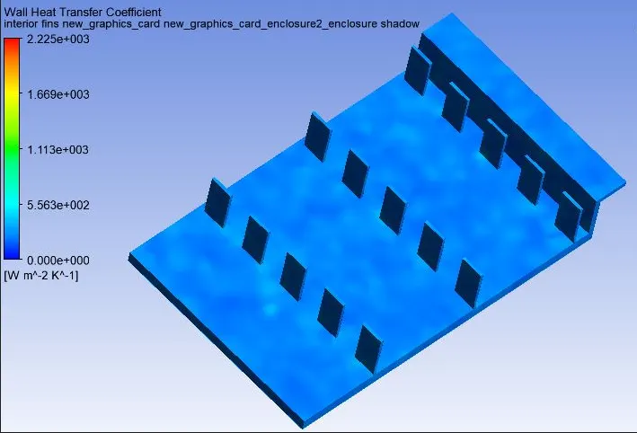
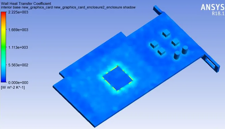
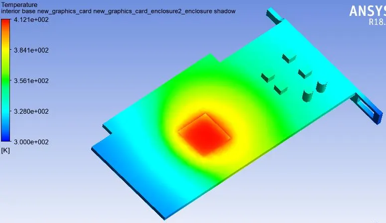
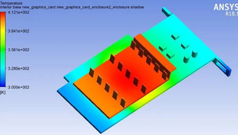
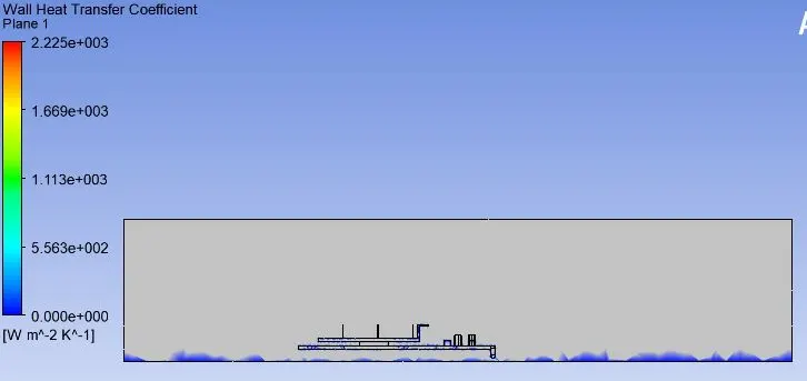
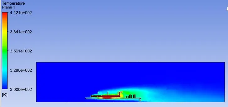
CASE-4-Refined Mesh(Velocity-5m/s).
Results.
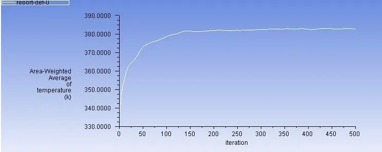
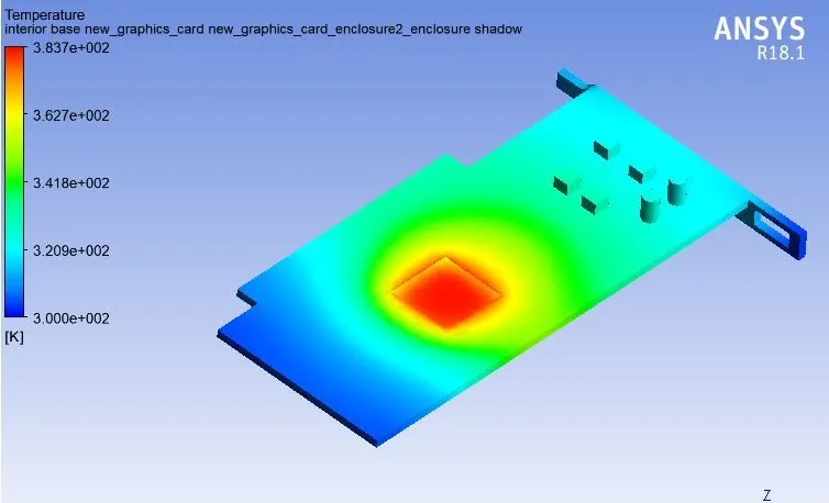
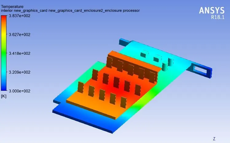
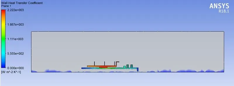
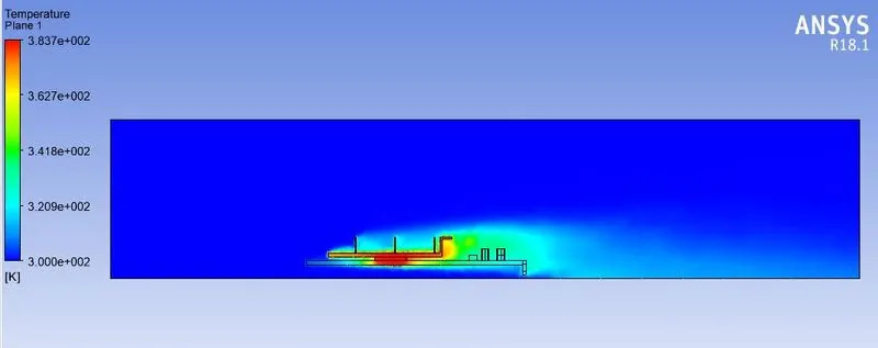
Temperature on the Graphics card.
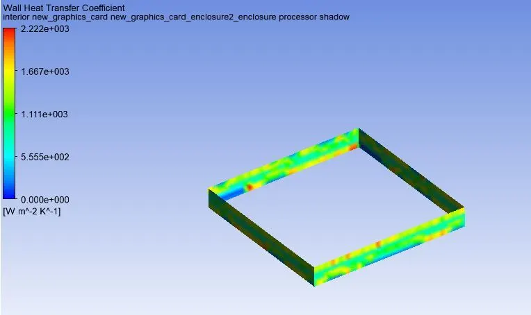
Conclusion.
| Sl.No. | Velocity (m/s) | Maximum Temperature (k) |
| Baseline mesh | ||
| case 1 | 1m/s | 509.48k |
| Refined Mesh | ||
| Case-2 | 1m/s | 515.48k |
| Case-3 | 3m/s | 411.17k |
| Case4 | 5m/s | 382.79 |
- As a result, it can be concluded that a higher inlet velocity leads to better cooling and a lower average temperature, protecting the components from harm.
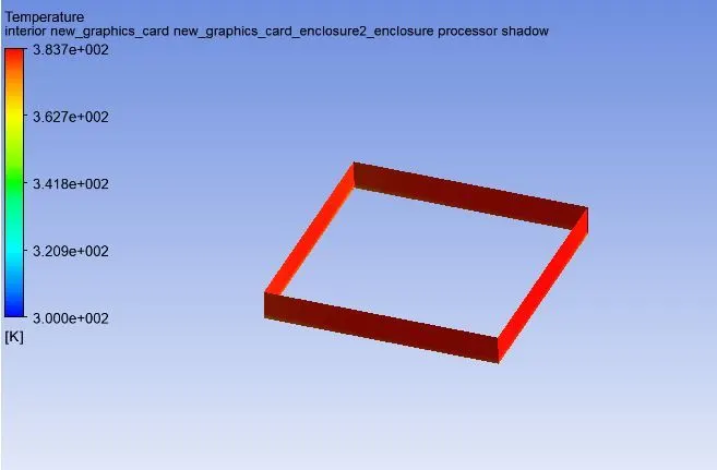
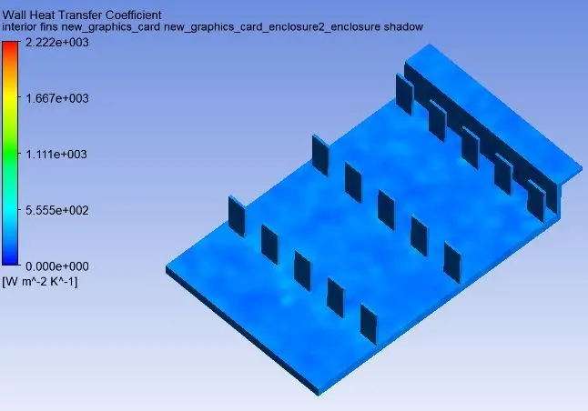
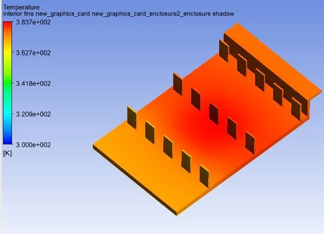
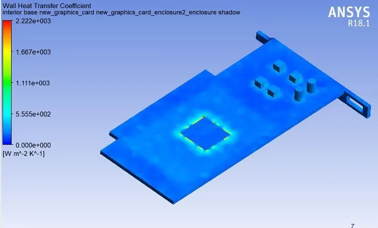
- The processor is considered to be the main heat source of the graphics card, which in operation, produces a lot of heat. We have carried out 3 case studies wherein we have increased the air inlet velocity to study the effects of cooling. Here, we can observe from the cases that, as we increase the inlet flow velocity of air, it thereby leads to a reduce in the temperature of the processor. Thereby, an increase in inlet flow velocity leads to more efficient cooling of the processor. The processor can be maintained at optimal temperature by increasing the inlet velocity of air, thereby reducing the chances of damage.
- Since the refined mesh have the higher number of mesh elements, it gives more accurate results compared to the base line mesh. Although the base line mesh takes less computational time compared to refined mesh case, it doesn't provide accurate results. So, the refined mesh is chosen in order to get the best result for this simulation.