Week 6 - CHT Analysis on a Graphics card
Aim:
Conjugate Heat Transfer Analysis of a graphics Card.
Objective:
To mesh the geometry given with proper mesh length.
To set up Boundary conditions and choose solver.
To plot the Results showing that the simulation has achieved convergence
To find out the maximum temperature and heat transfer coefficient attained by the processor
To Identify potential hotspots on the model.
To Repeat above for 3 different inlet velocity condition.
Compare the Results.
Theory:
Graphics card:
A graphics card (also called a video card, display card, graphics adapter, GPU, VGA card/VGA, video adapter, or display adapter) is an expansion card which generates a feed of output images to a display device (such as a computer monitor).
What is CHT Analysis,its Usage and importance:
CHT stands for conjugate heat transfer.It is used where both heat transfer in fluids and solid takes place simultaneously.
Since these are two different phenominon and two different physics involved in both type of the heat transfer,hence factors affecting both types of heat transfer is taken into consideration.
Heat transfer in solid takes place through coduction that is molicules do not have to leave their place to transfer heat.Heat transfer tin fluids takes place through convection in which molicular as well as particle movement happens during heat trasfer.
Practicle situations whenre conjugate heat transfer happens are heat exchangers, heaters, coolers etc where a hot or cold fluid flowing on a solid surface transfer heat with the fluid through convection and at iterface of solid and liquid heat is transferred through conduction surface through .
Dimensionless Numbers associated with conjugate heat transger:
Nusset Number(Nu):
It is the ratio of covective heat trasferred to the heat transfer through conduction.Based on Nusset number value dominating nature of mode of heat transfer can be assessed.
If Nusset no zero is then heat tranfer is purely through coduction.It is clossely related to Rayleigh Number .
In free convection(buonancy driven flow) Nusset is function of Rayleigh number and Prandtle Number,while in forced convection Nusset Nusset Number is function of Reynold Number and Prandtle Number.
Rayleigh Number(Ra):
It is defined as the product of Grashoff number and prandtle number.
Ra=Gr*Pr
Grashoff Number(Gr):
It is defined as the ratio of buoyancy force to viscous force.It is analogous to Reynold Number and used in free convection.
Reynolds Numbe(R):
It is defined as the ratio of inertia force to viscous force.It is associated with forced convection.
R=ρ*V*d/μ
μ=viscosity
Prandtle number(Pr):
It is defined as the ratio of momentum diffusivity to thermal diffusivity. Empirical formula for Prantle number is
Heat Transfer through Convection:
Heat transfer through convection can be written using Newton's Law of cooling.
q=hA(Ts-Tf)
h=Heat transfer coefficient
Heat TransferThrough conduction:
Heat transfer through conduction can be calculated using Fourier's Law of conduction.
Q=kA∂t/∂x
k=Thermal Conductivity
Y+ Value:
To check if the mesh is fine enough to catch the boundary layer near the walls, a measurement called y+ describing a dimensionless wall distance is often used.
y+ =(y*.u*)/ν
u∗ is the velocity at the wall
y∗ - cell length at the wall
ν - kinematic viscosity.
The grid quality, as mentioned above for y+, is another important measurement. The wall boundary layer, for viscous simulations, should be meshed according to the y+ equation and is the finest meshed area in the grid and we need to ensure that our y+ values are within a certain range. It's important to ensure Y+ values are not so large that the first node falls outside the boundary layer region. If this happens, then the wall functions used by the turbulence model may incorrectly calculate the flow properties at this first calculation point which will introduce errors into pressure drop and velocity results.
Geometry:
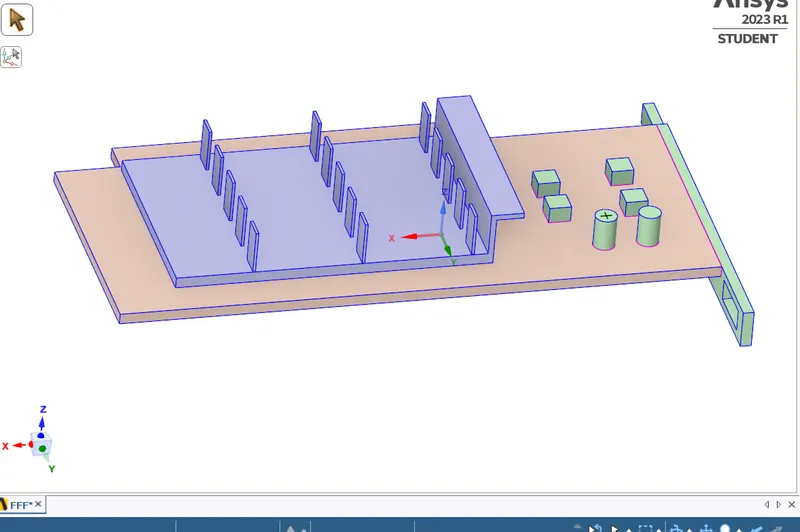
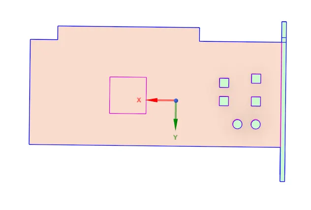
There are total four component of model
1-Processor
2-Fin
3-Pcb
4-Enclosour
- To ennable Share topology in Workbench.

Mesh:
Mesh Detalils:
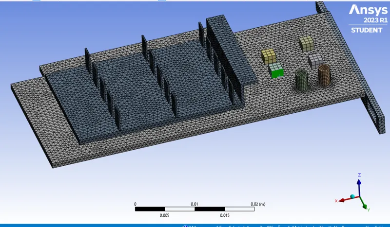
To create Body sizing to provide a combination of element size for different component.
To create Following named selection
1-Inlet
2-Symmetry
3-outlet
4-Fin
5-Pcb
6-Processor
Grid Independent test:
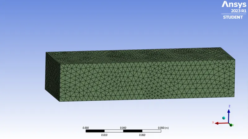
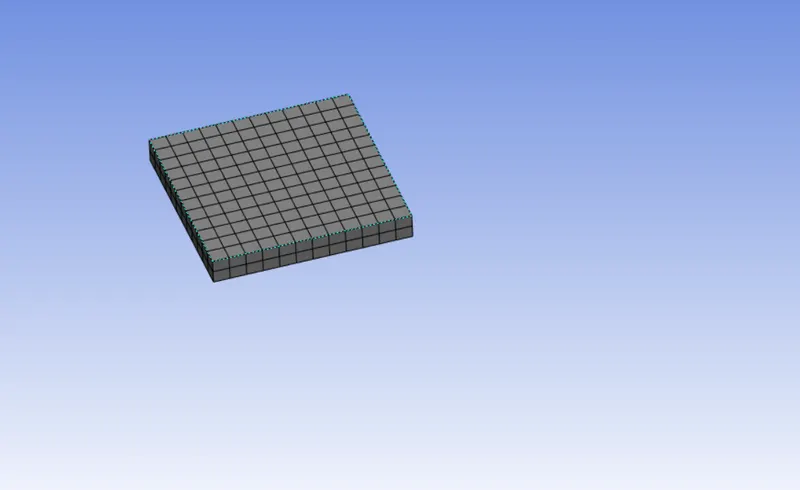
- Mesh is generated for three different size of mesh element to perform grid independent test.
- Maximum temperature and surface heat transfer coefficient at processor wall is calculated .
- Velocity at inlet is kept as 2m/s and temperature as 300K.
Case1:
| Case 1 | Case2 | Case3 | |||
| material |
fin(alluminium) processor(silicon carbide) PCB(fr4-glass-reinforced epoxy laminate) enclosure(air) |
fin(alluminium) processor(silicon carbide) PCB(fr4-glass-reinforced epoxy laminate) enclosure(air) |
fin(alluminium) processor(silicon carbide) PCB(fr4-glass-reinforced epoxy laminate) enclosure(air) |
fin(alluminium) processor(silicon carbide) PCB(fr4-glass-reinforced epoxy laminate) enclosure(air) |
fin(alluminium) processor(silicon carbide) PCB(fr4-glass-reinforced epoxy laminate) enclosure(air) |
| element size |
fin(body sizing(1mm)) processor(body sizing) PCB(body sizing(1mm)) enclosure(10mm) |
fin(body sizing(0.8mm)) processor(body sizing-0.8) PCB(body sizing(0.8) enclosure(8mm) |
fin(body sizing(0.7mm)) processor(body sizing-0.7) PCB(body sizing(0.7) enclosure(7mm) |
fin(body sizing(0.65mm)) processor(body sizing-0.65) PCB(body sizing(0.65) enclosure(6.5mm) |
fin(body sizing(0.6mm)) processor(body sizing-0.6mm) PCB(body sizing(0.6mm)) enclosure(7mm) |
| Total no of elements | 199523 | 296637 | 373220 | 428006 | 499027 |
| maximum temperature attained by processor | 317.58 | 317.18 | 317 | 316.94 | 316.88 |
| surface heat transfer coefficient at processor | 6.71 | 6.14 | 6.02 | 6.49 | 6.30 |
- Due to limitation of academic ansys further element size can not be reduced.But to achieve best combination of element size further refinement in element size is needed.
- For further study most refined element size has been taken.
Mesh Quality
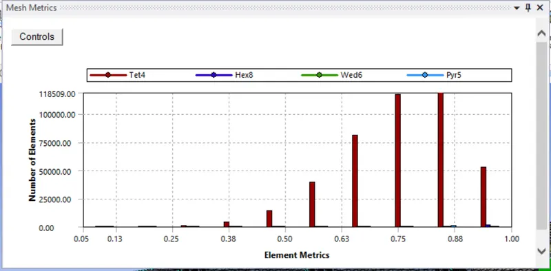
1-Element quality:It is the ratio of the volume to the sum of the square of the edge lengths for 2D quad/tri elements.A value of 1 indicates a perfect cube or square while a value of 0 indicates that the element has a zero or negative volume.
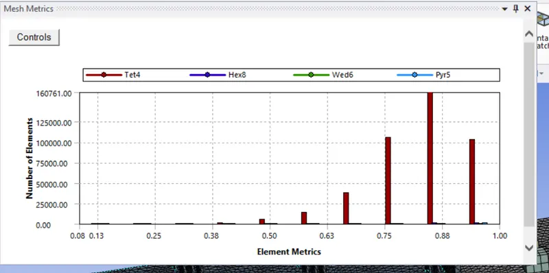
2-Orthogonality:
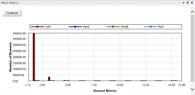
3- Aspect Ratio:
The aspect ratio of a triangle provides a comparison of the “height” and “width” of a triangle.
It varies from 1 to infinite. A value of 1.0 indicate an equilateral triangle.
The aspect ratio of quadrilaterals provides a comparison of a long side to a short side of the quadrilateral.
It varies from 1 to infinite. A value of 1.0 indicates a square.
4-Skewness:
Skewness determines how close to ideal (equilateral or equiangular) a face or cell is.
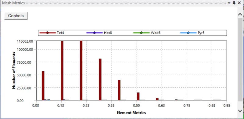
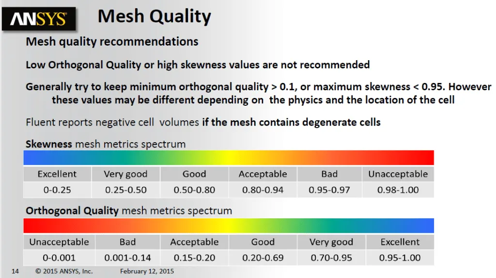
From the literature provided by ANSYS mesh quality can be seen under good condition.
Setup and Solver:
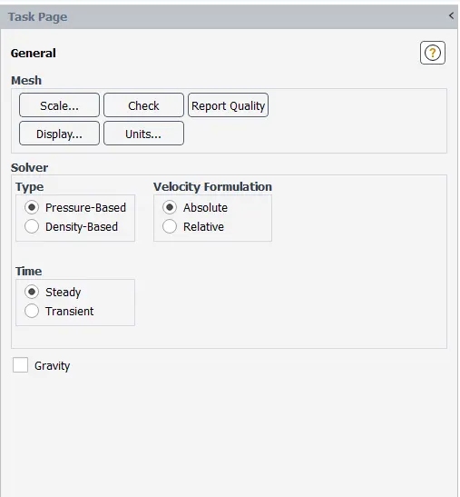
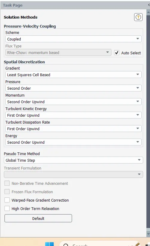
Since present study is for low velocity and incompressible fluid and focus is only on end results hence Steady simulation has been done using pressure based solver.
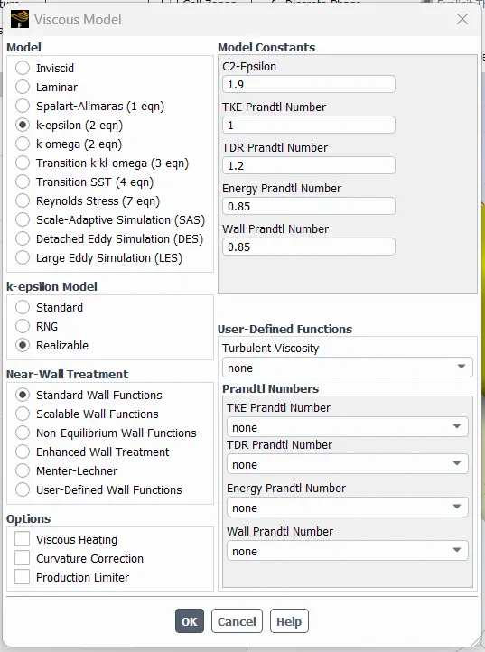
k-epsilon model is used
Materials:
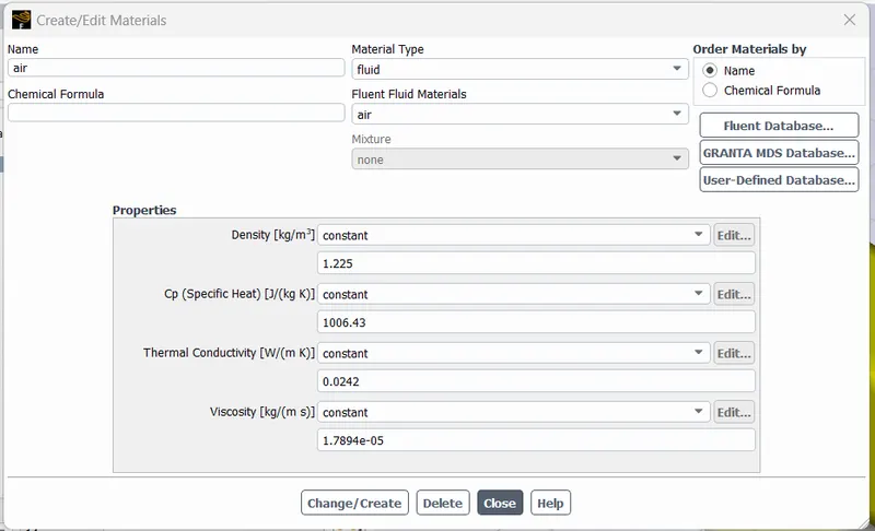
Air:
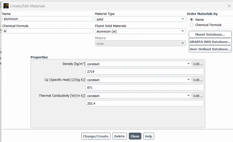
Alluminium:
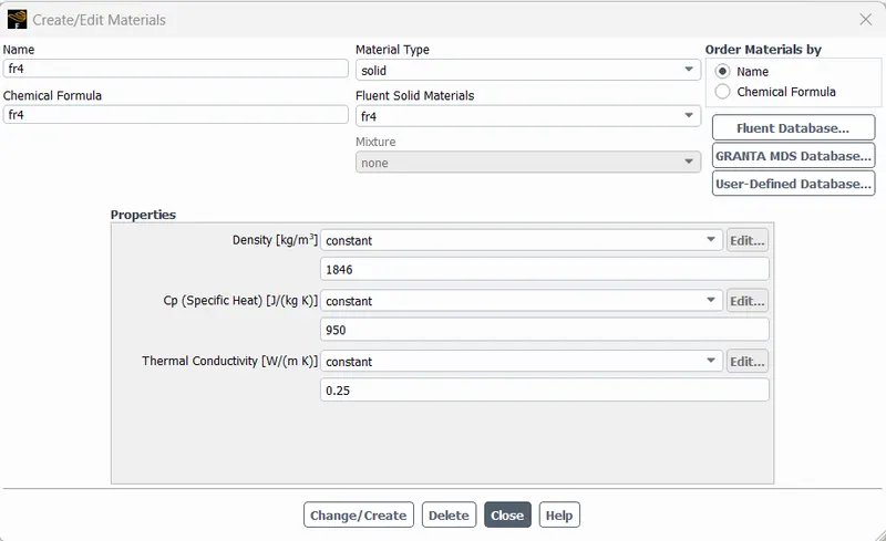
Glass-reinforced epoxy laminate(fr4):
Silicon Carbide:
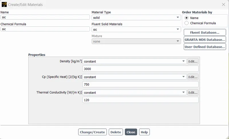
Boundary:
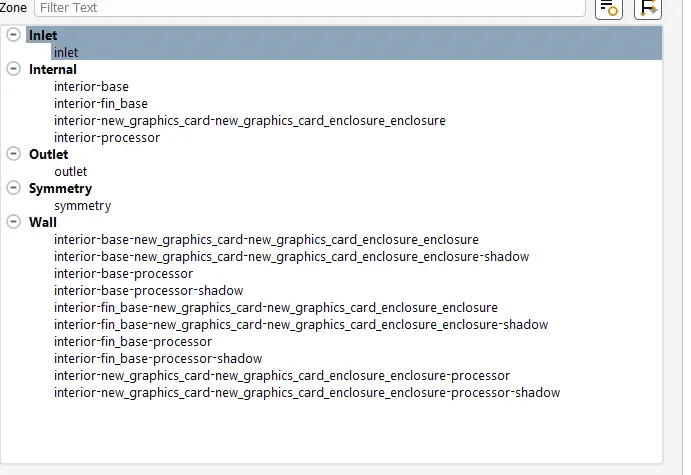
Cell-Zones

Boundary condition:
| Inlet velocity(m/s) | Inlet Temperature(K) |
outlet pressure (Pa) |
heat source (W/m^3) |
|
| Case 1 | 1 | 300 | 0 | 15625000 |
| Case2 | 3 | 300 | 0 | 15625000 |
| Case3 | 5 | 300 | 0 | 15625000 |
Where to provide heat source:
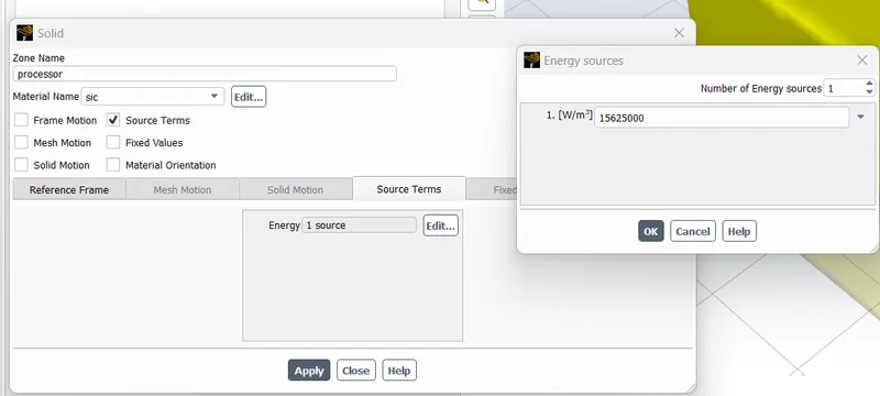
Results:
Case-1 velocity at the inlet is 1 m/s:
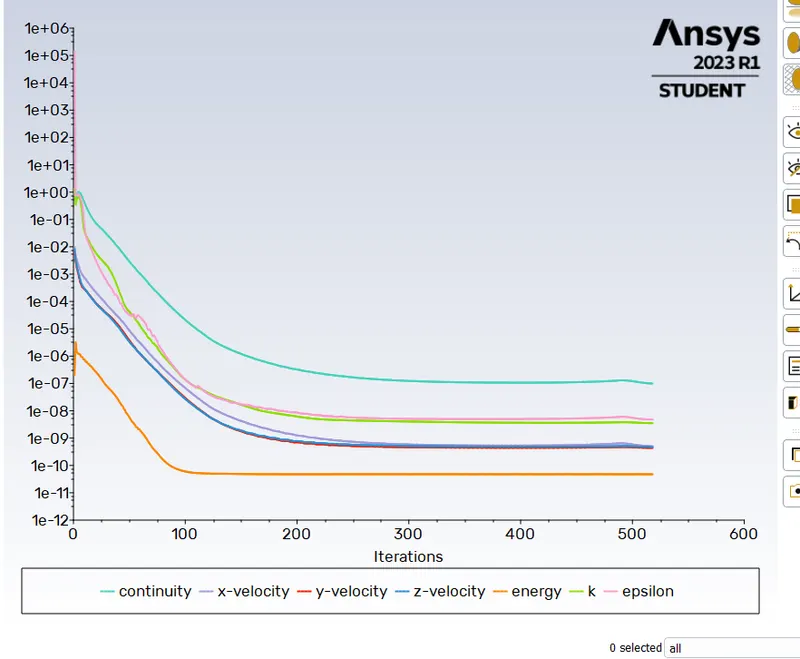
Convergence Plot:
Scale Residuals:
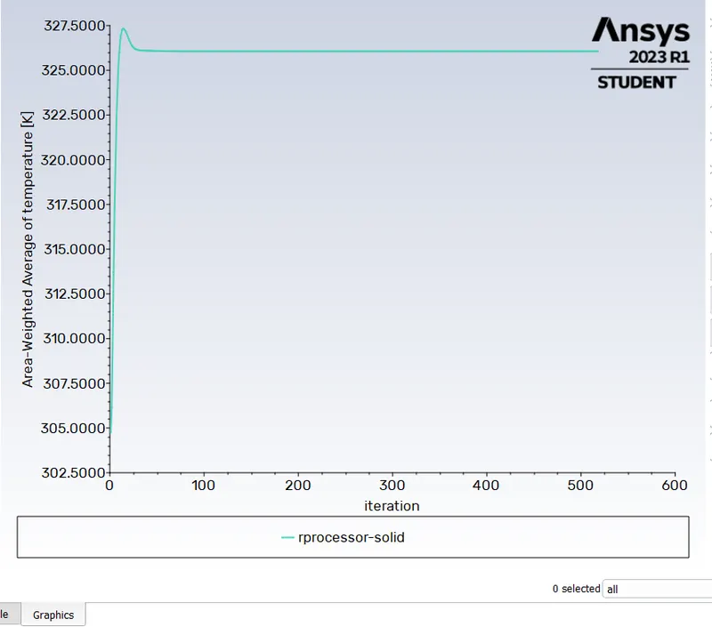
Area Weighted Average or Temperature:
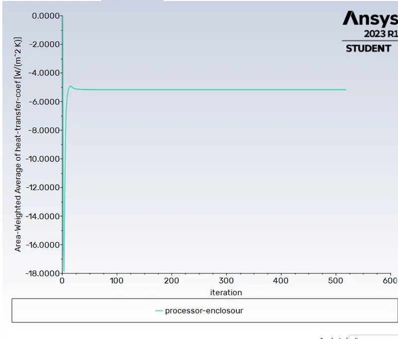
Area Weighted Average of Heat Transfer Coefficient:
Results:
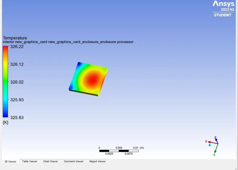
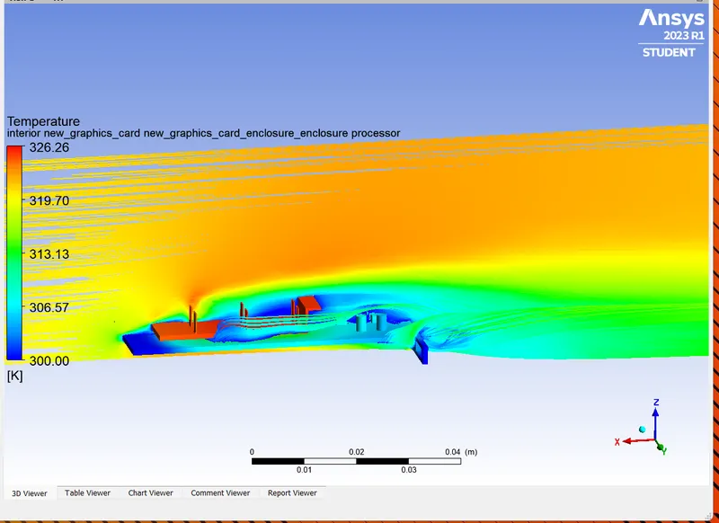
- Maximum teperature attained by the processor is 226K .
- Heat is getting conducted through the fin from processer and then getting covected in the air.
- Heat is also getting convected through the processor wall which are in contact with air.
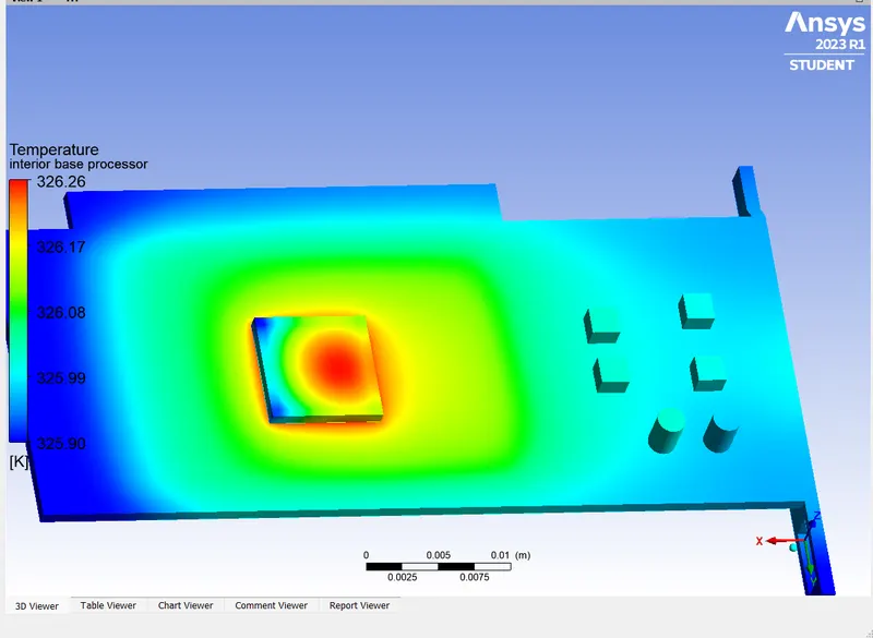
- Sice PCB material has low thermal conductivity hence temperature achieved by it is comparitively low and face whic is directly facing the comming air has lesser temperature of all PCB surface.
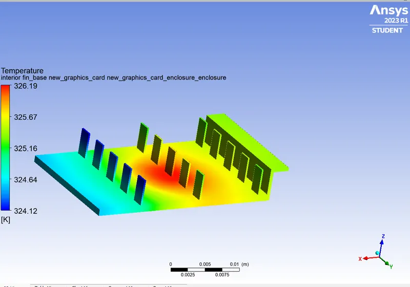
- Heat is getting coducted through fin and since fin material has high thermal conductivity it has almost same maximum temperature as processor .
- leading edge of the fin is facing the incoming low temperature air hence convection is happening at faster rate and temperature here is lower.
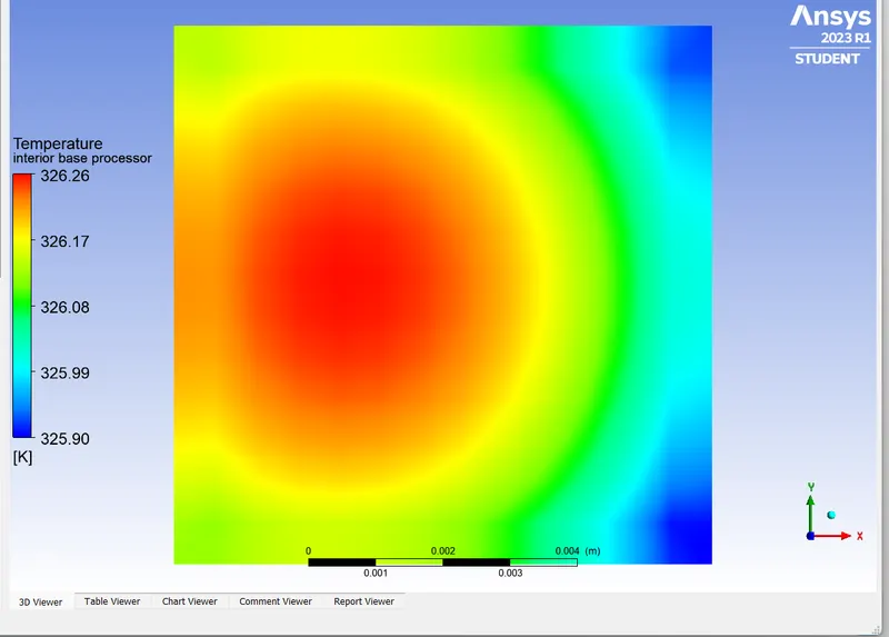
- At the centre of the fin face there is maximum tempreature dure to direct cotact with processor.
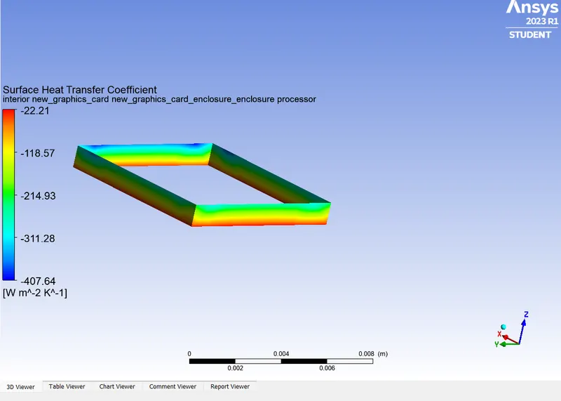
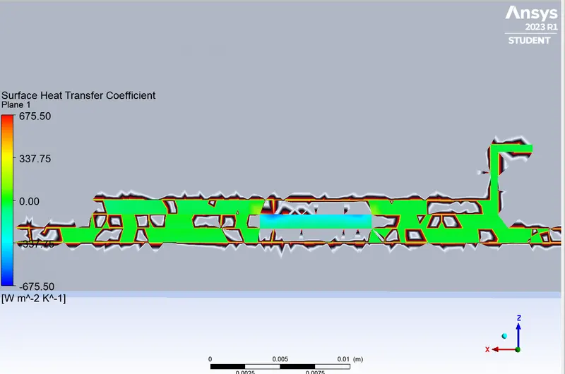
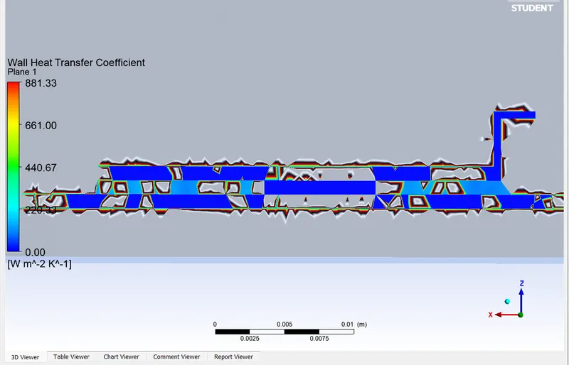
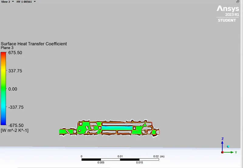
The above image show the surfac eheat transfer coefficient at the processor wall that are in cantact with air.
Here convection is happening and heat transfer coefficient value is 5.17 W/m^2 K.
There is negative sign with heat transfer coefficient because heat is geggtin convected out of the system.
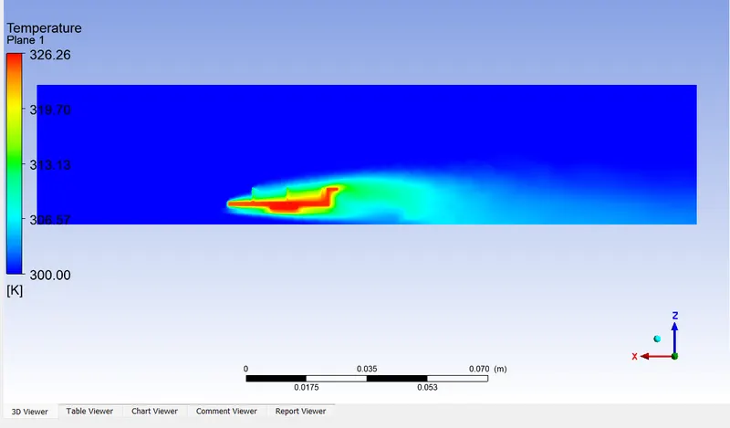
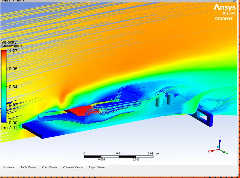
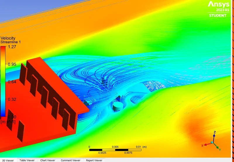
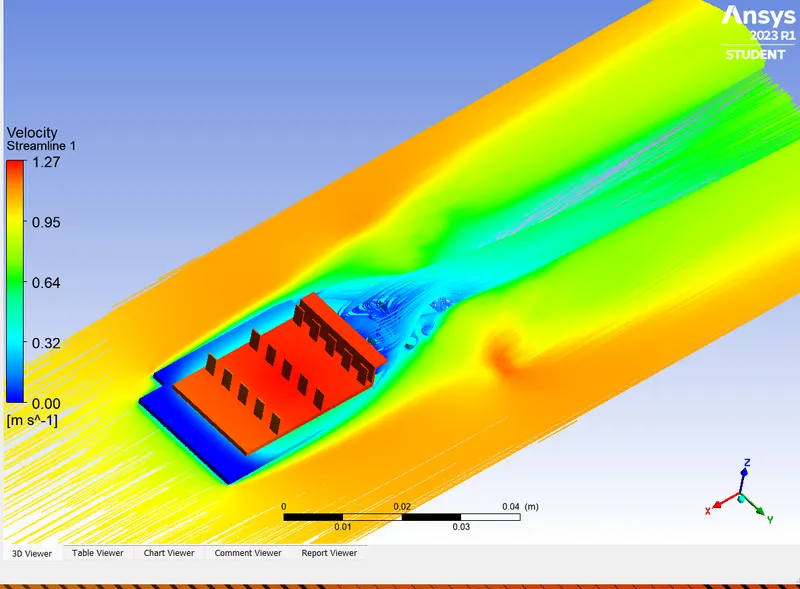
- Air that is in direct contact of fin and processor has comparitively highier temperature
- Temperature of air away from the graphics card or that passes beneath the psb are at ambient temperature
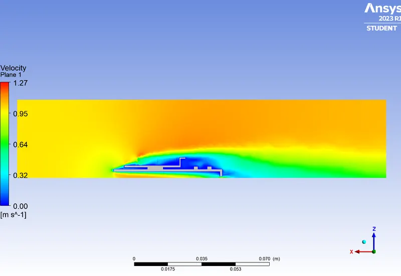
Hot Points:
- The potential hot point is at the centrenof proceesssor and at the centre of fin surface as well .
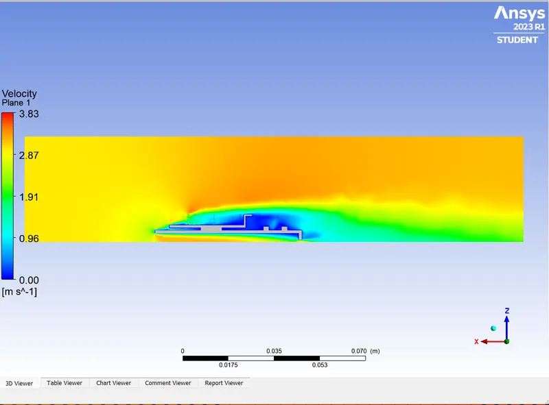
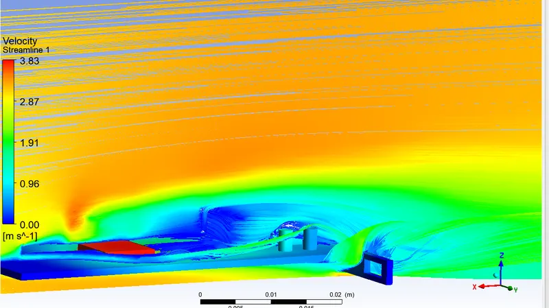
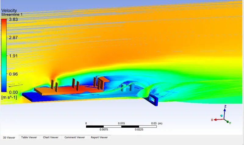
CASE2 When inlet velocity is 3m/s:
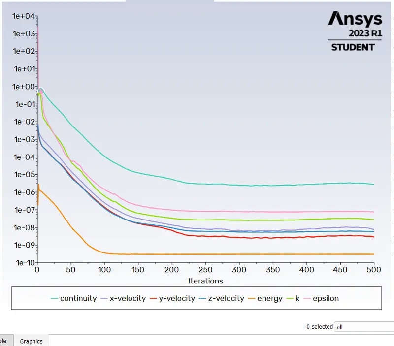
Convergence plot:
Scale Residuals:
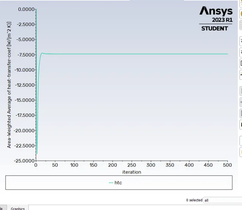
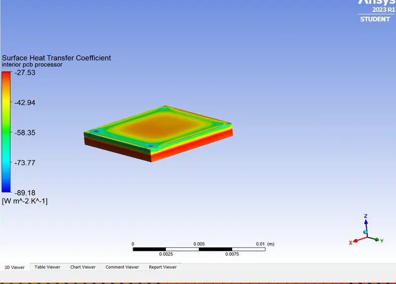
Area Weighted Average of Heat Transfer Coefficient:
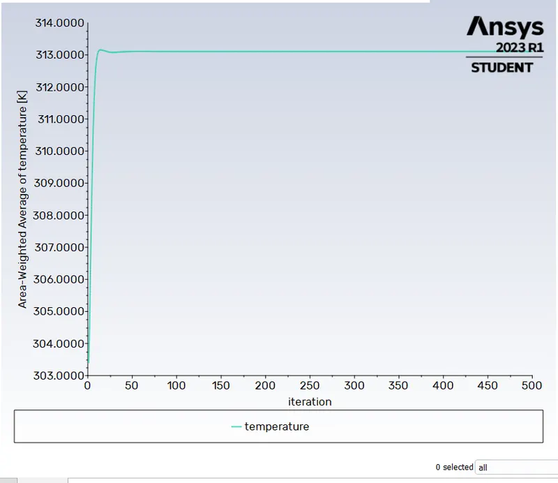
Area Weighted Average of Temperature:
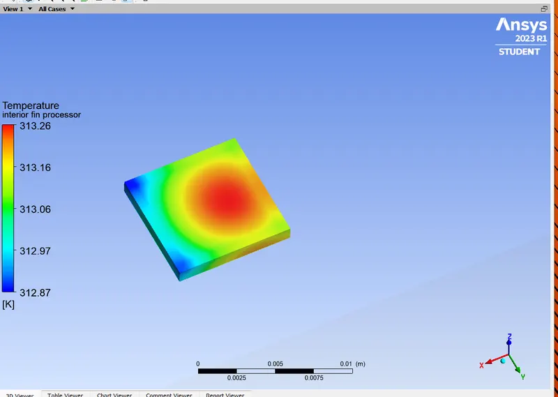
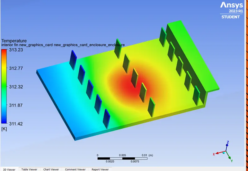
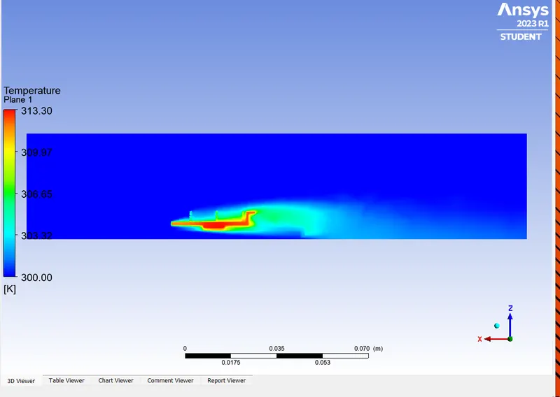
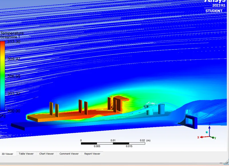
Temperature contours:
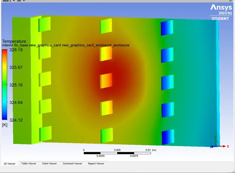
- Maximum temperature attained by the processor is 313.26 which is at the centre of the processor.
- This temperature is slightly lower than that in the previous case because of increased air velocity
and hence this has improve the convection rate incresing more heat convected out of the system.
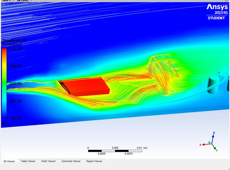
Hot Points:
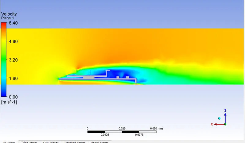
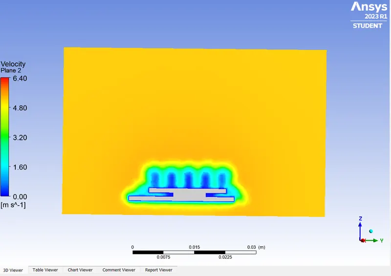
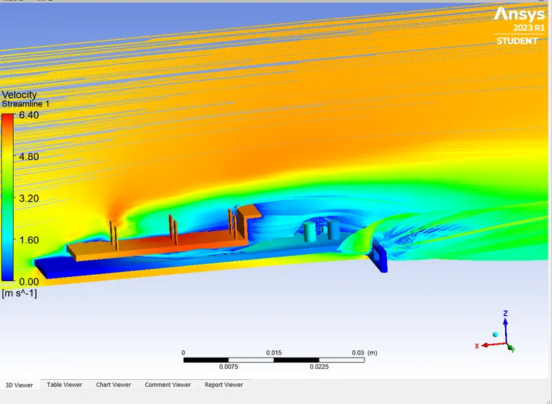
Case3 when inlet velocity is 5m/s:
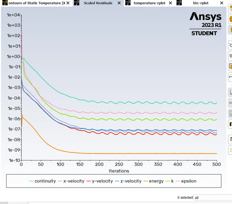
scale residuals:
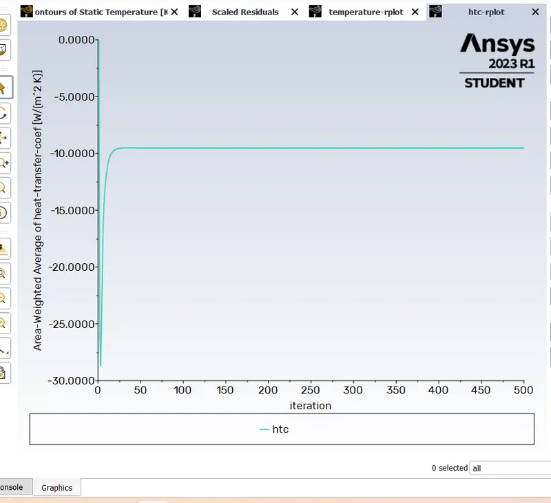
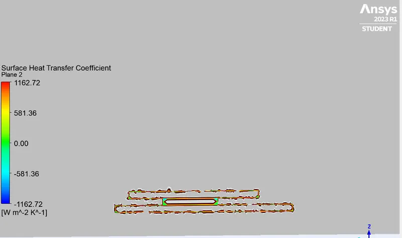
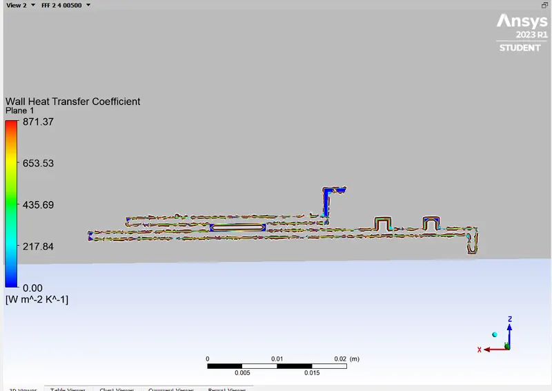
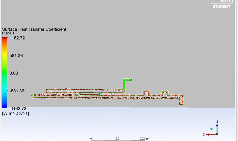
Area Weighted Average of Heat Transfer Coefficient:
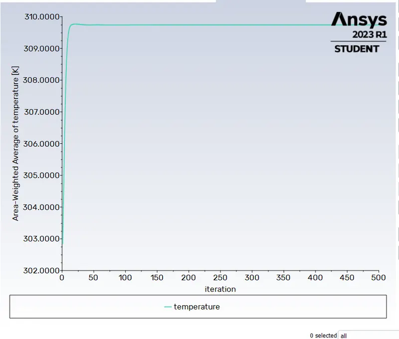
Area Weighted Average of Temperature:
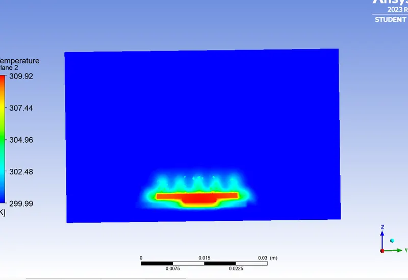
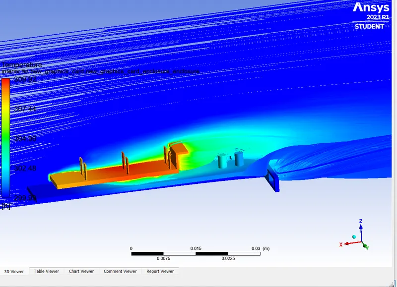
Temperature contour:
- Maximum temperature attained by the processor is 309.92 which is at the centre of the processor.
- This temperature is slightly lower than that in the previous case because of increased air velocity
and hence this has improve the convection rate incresing more heat convected out of the system.
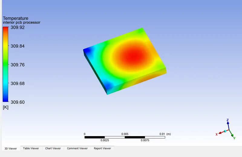
- Maximum teperature attained by processor is minimum of all case as velocity of air is maximum in this case.
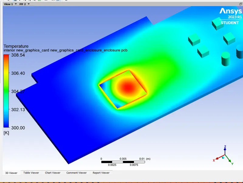
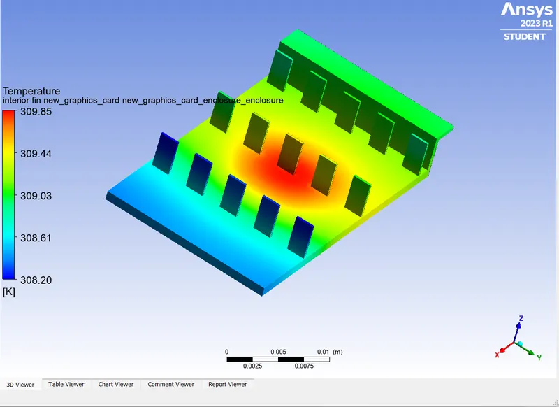
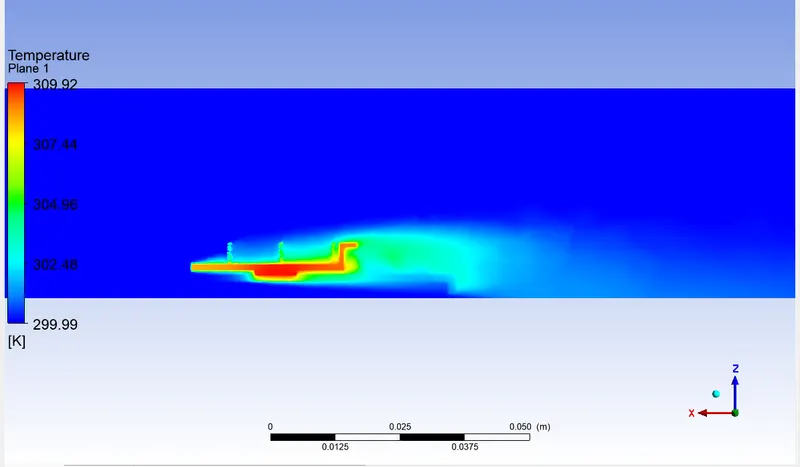
Hot Points:
Conclusion:
| Case1(inlet vel.1m/s) | Case2(inlet vel.3m/s) | Case3(inlet vel.5m/s) | |
| Heat transfer Coefficient(W/m^2 K) | 5.15 | 7.38 | 9.52 |
| Maximum Temperature(K) | 326 | 313 | 309 |
- With increase in inlet air velocity heat transfer coefficient value increases and hence heat convection rate that is why there is reduction in maximum temperature attianed by the processor .
- Heat transfer coefficient depend on many other factor as environment condition in which the heat is being convected temperature velocity and pressure viscosity etc.