Week 6 - CHT Analysis on a Graphics card
CHT Analysis on Graphic Card
Objectives:
Run the simulation by varying the velocity from 1m/sec to 5m/sec for at least 3 velocities and discuss the results.
Find out the maximum temperature and heat transfer coefficient attained by the processor.
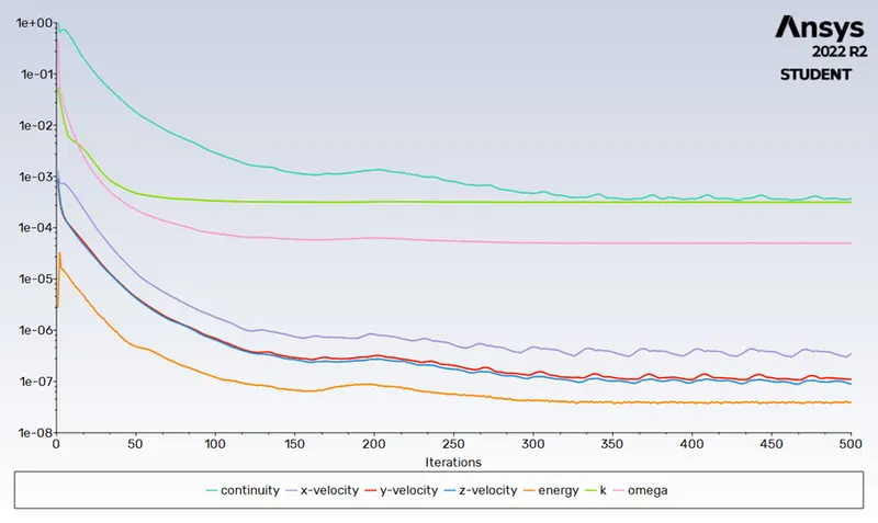
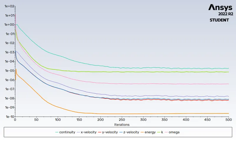
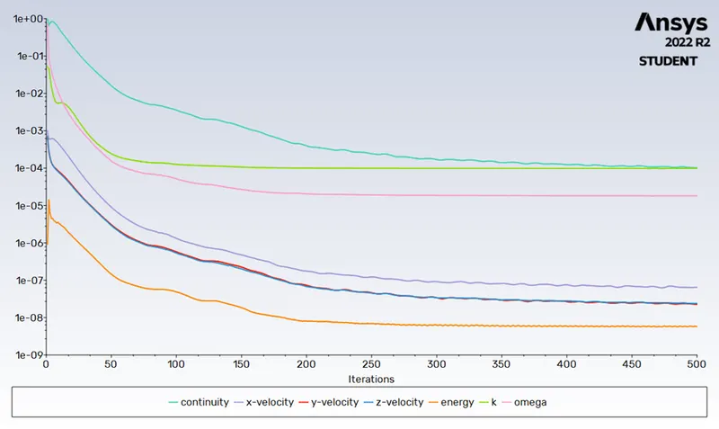
Prove that the simulation has achieved convergence with appropriate images and plots.
Identify potential hotspots on the model.
Introduction:
Graphics card is a hardware which is used to increase the video memory of a computer, and make its display quality more high-definition. It makes the computer more powerful and gives it the capacity to do more high-level works. The quality of the image depends on the quality of the graphics card. It is very much important for gaming and video editing on a PC. Every game needs a graphics memory to start and it depends on the type of the game, and the requirements are mentioned on the game box.
Conjugate Heat Transfer:
The heat transfer allows to exchange of thermal energy at the interface between the solid and fluid domain. In that case it is more stable and provides faster convergence as the energy equation is strongly coupled between the solid and fluid regions.
Applications of CHT are as below
The fluid usually plays the role of energy carrier on large distances. Forced convection is the most common way to achieve high heat transfer rate. In some applications, the performances are further improved by combining convection with phase change (for example liquid water to vapor phase change).
Heat sinks are usually made of metal with high thermal conductivity (e.g., copper or aluminum). They dissipate heat by increasing the exchange area between the solid part and the surrounding fluid.
By considering above applications the graphic card is another example of CHT. For the particular model we simulating the CHT on graphic card in a particular dimensioned box.
The application for CHT is like simulation of heat exchanger (Heat sink), cooling of electronic equipment (graphic card), general purpose of cooling and heating of system (shell and heat exchanger).
The Procedure and steps involved in simulation of Graphic card:
1. Graphic card geometry:
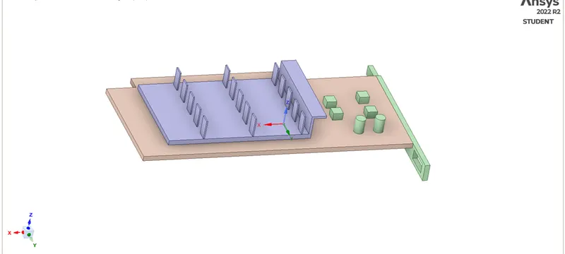
The graphic card geometry involves
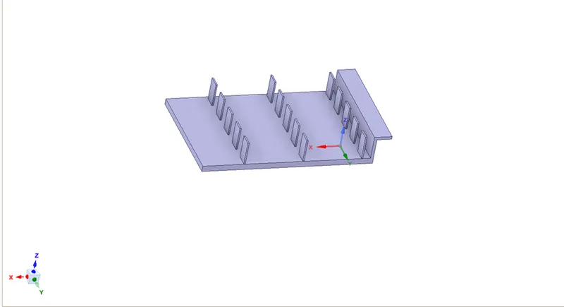
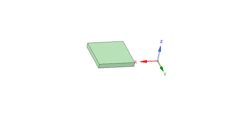
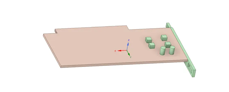
PCB Base, Fins and Processer and all parts are covered with the enclosure. Here before updating the geometry to meshing section we have to give share topology to the geometry (It avoids the overlapping mesh) and we can update the geometry to next section.
Fin Base geometry:
Processor geometry:
Base geometry:
2. Meshing:
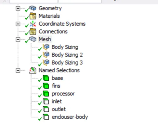
In this section we select the baseline mesh for each element of geometry with named selections.
The graphic card with enclosure body
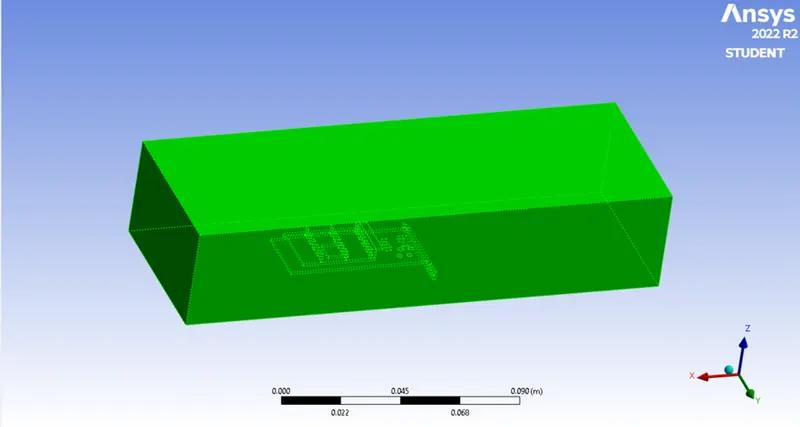
Baseline mesh for geometry:
Mesh sizes are
Enclosure: 0.005m
Base: 0.003m
Fins: 0.0012m
Processor: 0.0012m
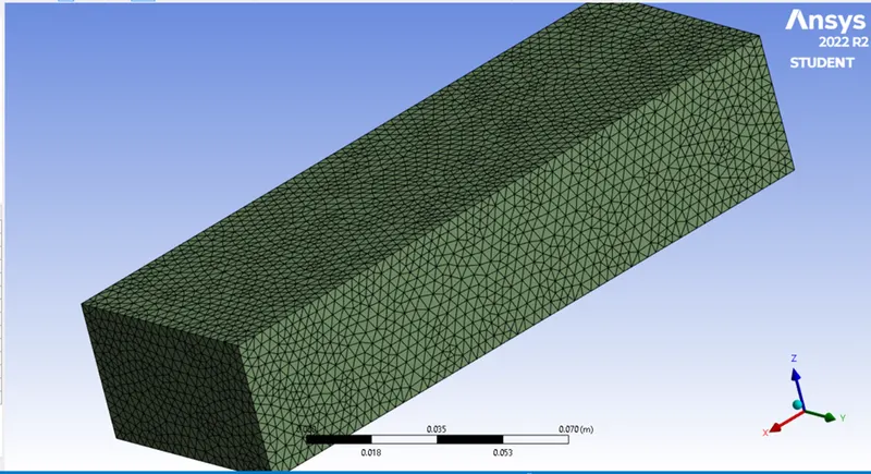
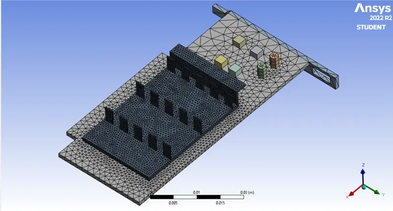
Elements: 87049
Nodes: 15896
Setup:
While setting up the properties of graphic card we consider a particular part should have a certain material selections with particular properties.
Check the mesh in console and enable the energy (energy equation to find the variation of Temperature).
Setting the turbulence module as K-omega (For less velocity and for checking the performance of heat near to the wall).
Selecting the materials as for solids are
Base (FR-4)
Density: 1800 Kg/m^3
Specific Heat (Cp): 1100 J/Kg K
Thermal Conductivity: 0.25 W/m K
Fins (Aluminum)
Density: Kg/m^3
Specific Heat (Cp): J/Kg K
Thermal Conductivity: W/m K
Processor (silica)
Density: 2330 Kg/m^3
Specific Heat (Cp): 710 J/Kg K
Thermal Conductivity: 148 W/m K
Selecting the cell zones for particular material to particular part with source term.
Considering the heat consumed by processor as 10 W
Calculation of source term:
Let the processor consume 10 W of power to work.
Dimension of the processor = 8*8*1 mm^3
So, Energy produced by the processor = 10/ ((8*8*1) *10^-9)
For processor allowing source term as 156250000 W/m^3
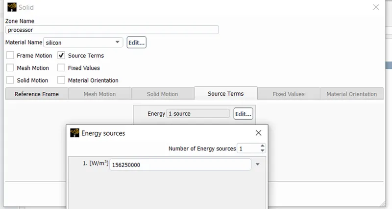
Applying the inlet velocity as 5 m/s.
Outlet Pressure as 0 Pa.
Temperature for inlet/outlet as 300 K.
Considering the enclosure body as wall.
Creating contour initializing the process and run the simulation at 500 iteration with coupled scheme ( It solves the equations in sequential form for residual plot).
Residual plot:
Maximum Temperature plot:
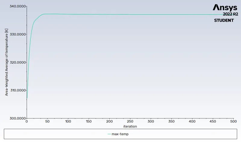
Maximum Temperature: 337.05 K
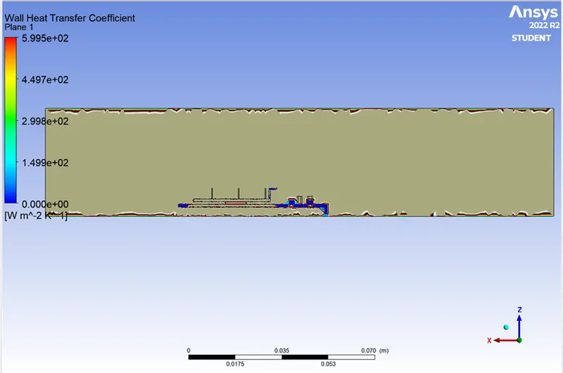
Heat Transfer Coefficient: 3.47 W/m^2 K
Post-Processing:
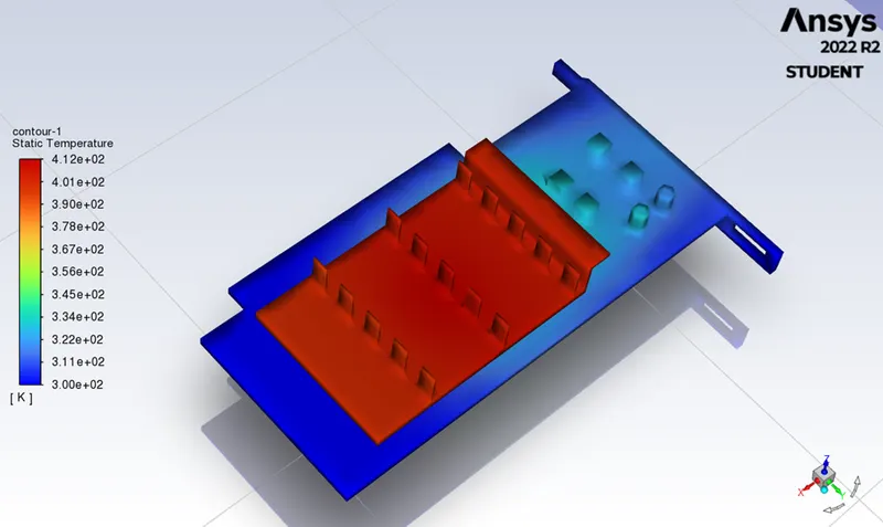
Hot spot temperature:
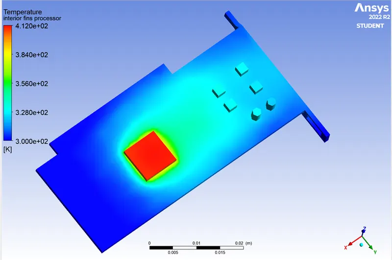
Temperature contour:
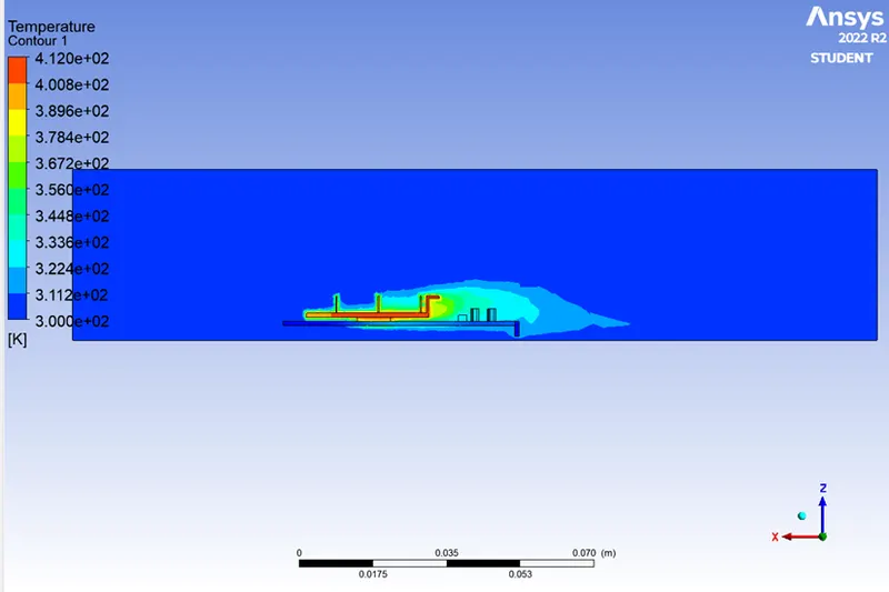
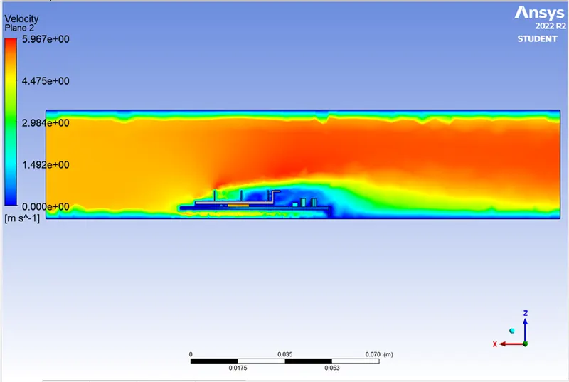
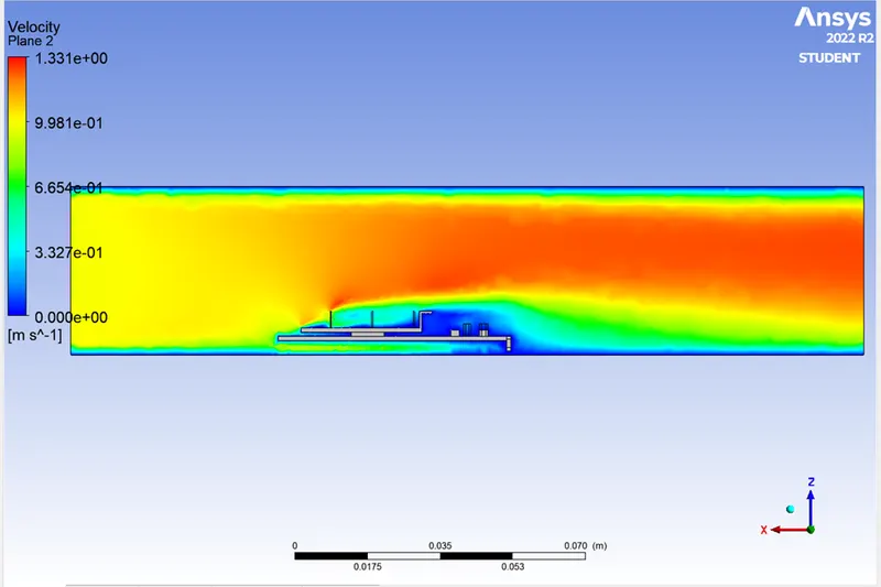
Velocity on graphic card:
Wall Heat Temperature:
CASE 1:
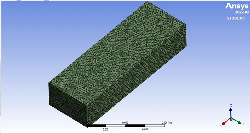
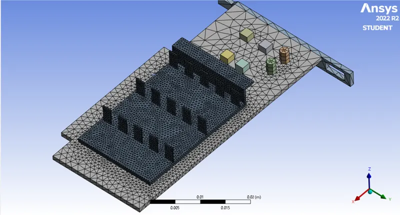
At velocity of 1 m/s With refined mesh of size
Enclosure: 0.003m
Base: 0.003m
Fins: 0.0005m
Processor: 0.0005m
Refined Mesh:
Setup:
Selecting the setup same as baseline simulation exclude the inlet velocity,
Mean the inlet velocity is applied as the 1 m/s.
Maximum Temperature:
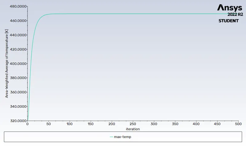
Maximum Temperature: 469.60 K
Heat Transfer Coefficient: 2.51 W/m^2 K
Post-Processing:
Hot-spot:
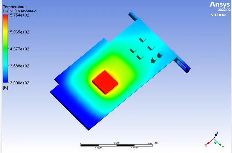
Temperature on graphic card:
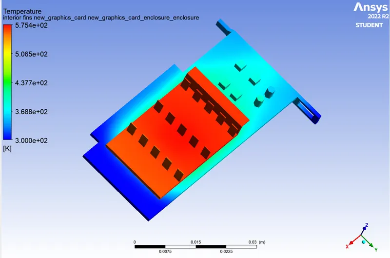
Temperature contour:
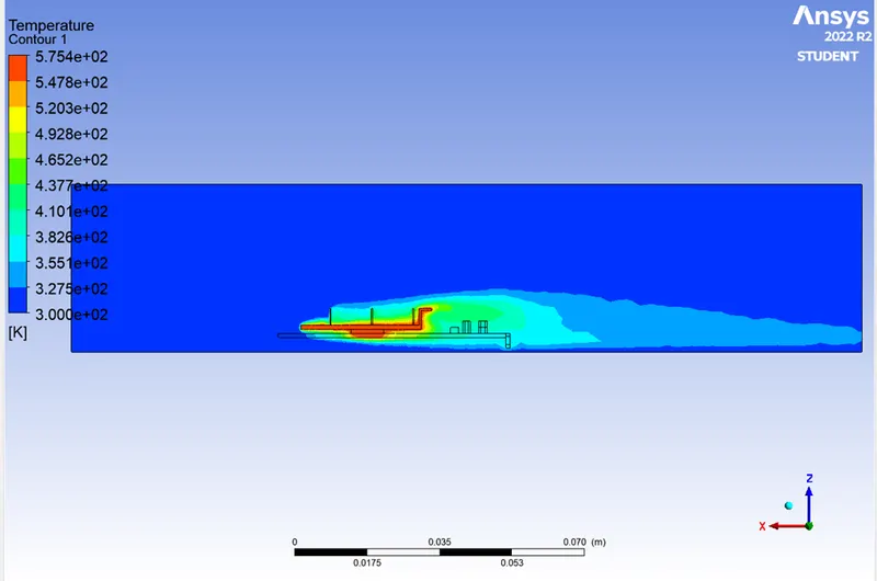
Velocity on graphic card:
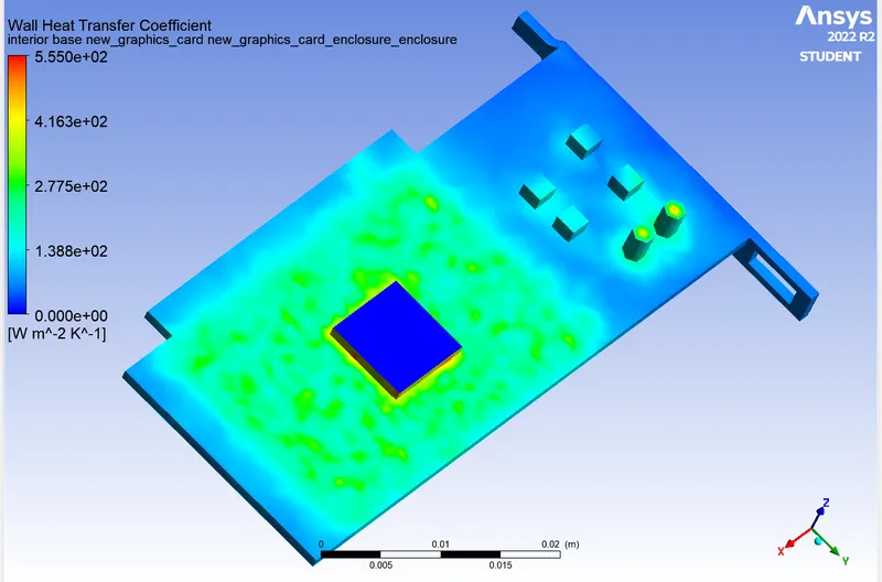
Heat Transfer Coefficient:
CASE 2:
Simulating the simulation at velocity of 3 m/s.
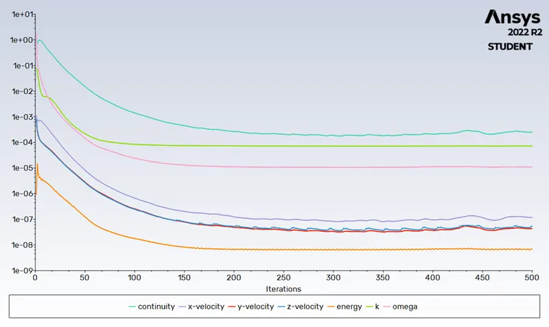
Residual plot:
Max.Temp:
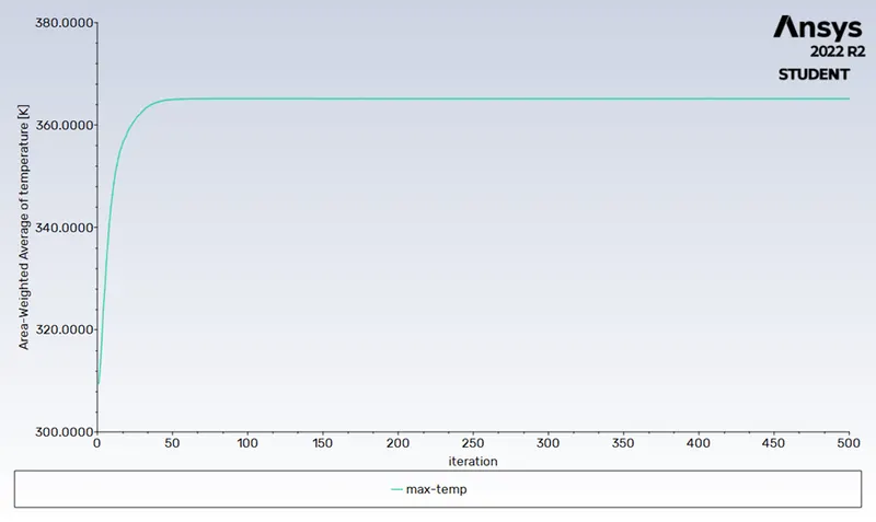
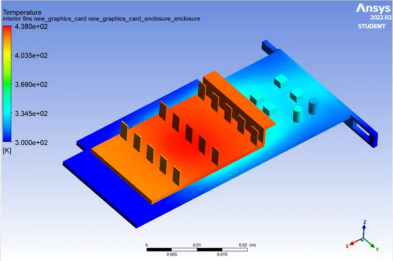
Maximum Temperature: 365.14 K
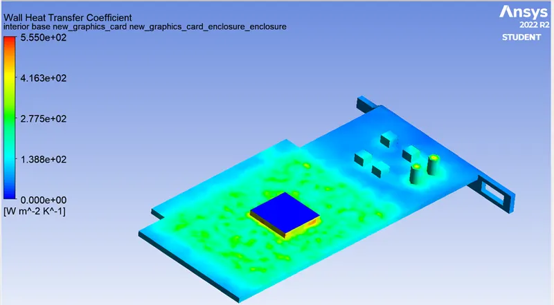
Heat Transfer Coefficient: 2.84 W/m^2 K
Post-Process:
Hot-Spot:
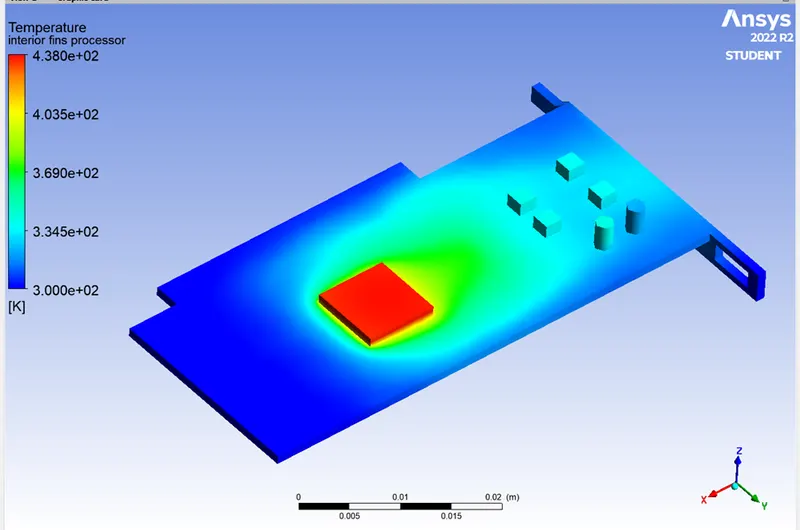
TEMPERATURE:
WALL HEAT TRANSFER COEFFICIENT:
CASE 3:
Simulation at velocity of 5 m/s.
Residual Plot:
Max. temp:
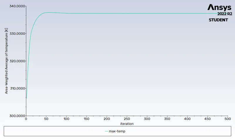
Maximum Temperature: 335.7 K
Heat Transfer Coefficient: 3.15 W/m^2 K
Post-process:
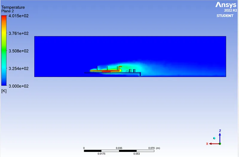
Hot-Spot:
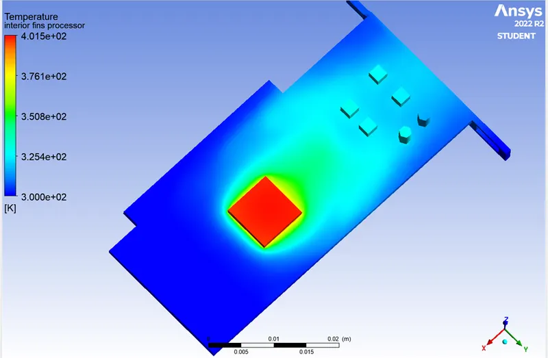
Temperature contour:
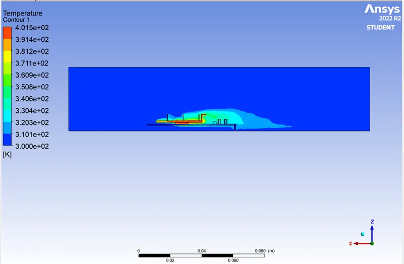
Temperature on plane:
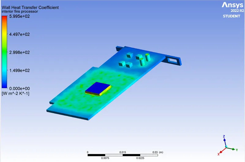
Wall heat Transfer coefficient:
Grid dependence test results:
|
Mesh at inlet velocity of 5 m/s |
Elements |
Maximum Temperature (K) |
Wall Heat Temperature (W/m^2 K) |
|
Baseline mesh |
87049 |
337.05 |
3.47 |
|
Refined mesh |
388267 |
335.07 |
3.15 |
Conclusion:
In above images we showed the results of simulation on baseline and refined mesh size.
Residuals do not provide information on the convergence to the steady state of the flow.
The temperature monitor for all the three cases reaches a steady state value and proves to be a great indicator of the convergence of the steady state problem.
In refined mesh geometry we applied different velocity for same mesh size part and found the heat variation and temperature variation applied during process on graphic card.
From the results and output get from simulations, we conclude that the baseline mesh size part will create more wall heat transfer coefficient on graphic card base.
As the inlet velocity is increases the hotspot/heat generation around processor will be decreases.
So, we conclude for this simulation is that provide more size with more inlet velocity to do not observe the more wall surface (base) area of heat transfer coefficient. Coz in baseline mesh we get the higher HTC than refined mesh size Graphic Card.