Week 6 - CHT Analysis on a Graphics card
AIM:
Perform a steady-state conjugate heat transfer analysis on a model of a graphics card.
OBJECTIVE:
- Run the simulation at 1m/s, 3m/s and 5m/s and obtain the results.
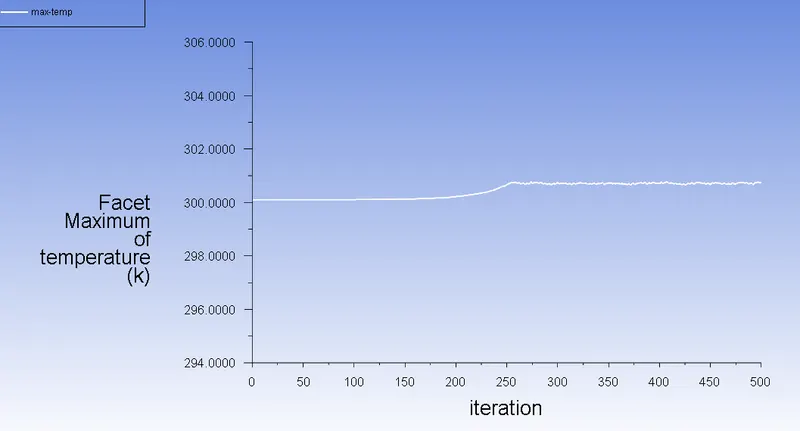
- Find out maximum temperature and heat transfer coefficient obtained by the processor.
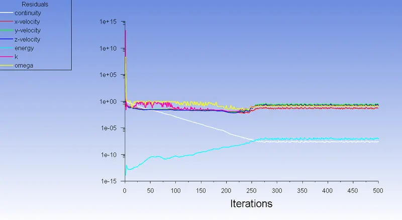
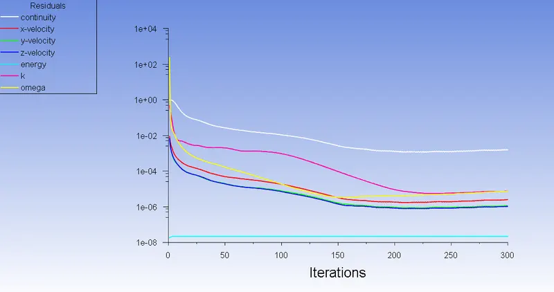
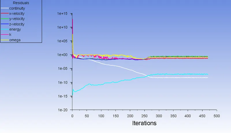
- Using residuals prove the convergence.
- Identify potential hotspots in the model.
- Run the simulation for best possible mesh with combination of coarse and refined mesh different regions.
INTRODUCTION:
CONJUGATE HEAT TRANSFER ANALYSIS
The Conjugate Heat Transfer (CHT) analysis type allows for the simulation of heat transfer between solid and fluid domain by exchanging thermal energy at the interface between them.
In solids, conduction often dominates whereas, in fluids, convection usually dominates.
The physics of conjugated heat transfer is common in many engineering applications, including heat exchangers, HVAC, and electronic components design.
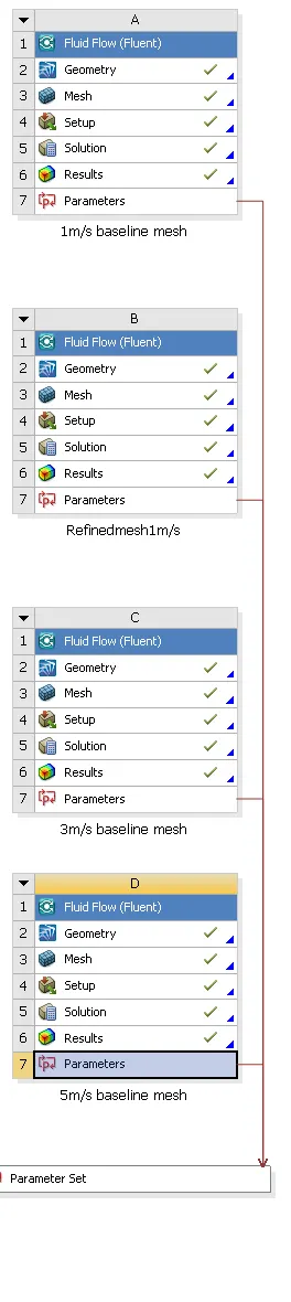
Flow chart of the problem in anysis is given below.
THEORY:
MATERIAL SELECTION
FLUID DOMAIN
- Air: For the fluid or coolant air used in the fluid domain.
SOLID DOMAIN
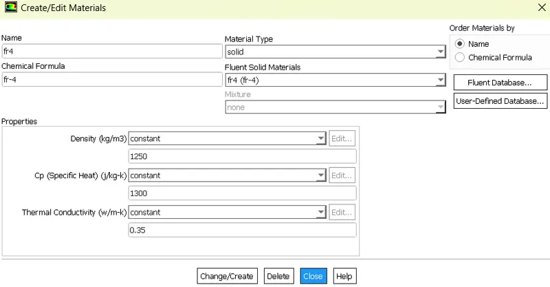
- FR4 Material: FR-4 is a glass-reinforced epoxy resin laminate that stands for “Flame retardant”. it has a high working temperature, good heat resistance, good moisture resistance, good hole metallization performance. Therefore it is preferred to build PCB. In this project FR4 is used for PCB with user defined properties in materials.
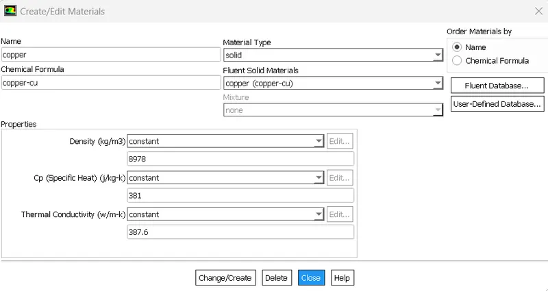
- Copper: Copper is a good conductor of heat therefore it was added to assign it to Capacitors. Copper is also user defined in this project.
- Silicon: Most of the processors are made of Silicon based material. R350 GPU’s are mostly Silicon based Graphics card processors. So silicon is used for as user defined material for processor.
- Aluminium: Aluminium is a good conductor of heat therefore it was added to assign it to Heat sink. Aluminium is taken from fluent database in this project.
PROCEDURE:
SOLVING AND MODELLING APPROACH:
- Geometry is made in spaceclaim
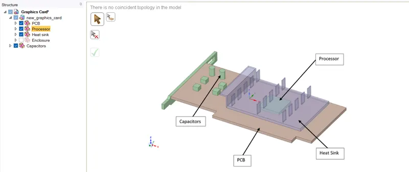
- For creating conformal mesh. Share topology is made between different parts.

PREPROCESSING AND SOLVER SETTING:
MESH SETTING:
- Open the mesh
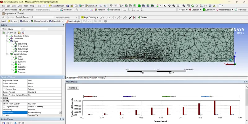
- Run baseline mesh with 5 mm mesh length for 1 m/s.
|
Named Selections |
Element size |
|
Enclosure |
5 mm |
|
PCB |
0.25 |
|
Capacitors |
0.3 mm |
|
Heat Sink |
0.1 mm |
|
Processor |
0.1 mm |
Baseline Mesh
|
Nodes |
38736 |
|
Elements |
210849 |
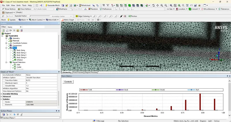
- After 1st round simulation Run refined mesh.
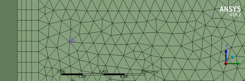
Inflation layer with 0.2 mm total thickness on all parts.
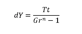
Where Gr is growth rate , n is number of layers , Tt is total Thickness and dy is first layer thickness.
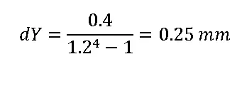
It is noted to have 0.25 mm as first layer thickness. For more refining element size is fixed to 0.2 mm inflation for higher quality.
|
Nodes |
2149379 |
|
Elements |
12821944 |
SOLVER SETTING :
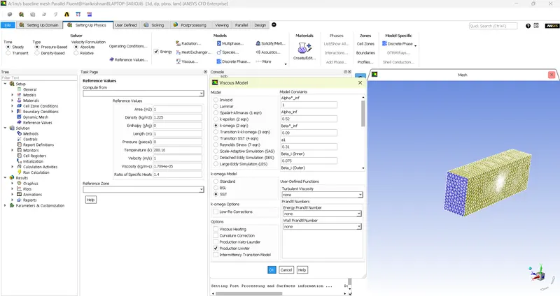
- Model:Pressure based – steady state flow, Viscous -K-W SST selected and Thermal selected.
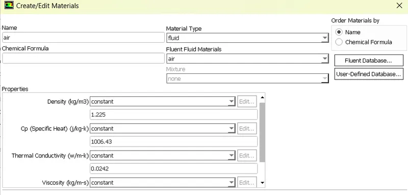
- Materials= Air in fluid domain.
- Materials= For solid domain
- FR4 for PCB
- Copper for Capacitor
- Aluminium for Heat sink
- Silicon for processor

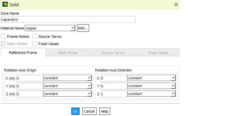
- Cell zones selected and assigned Source term for Processor. It is assumed to have 1W power utilization by processor, So total heat generated for source term will be Power/Volume = [1 x 10⁹/(8x8)]=15625000 W/m3.
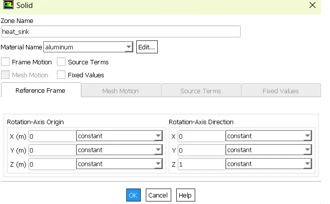
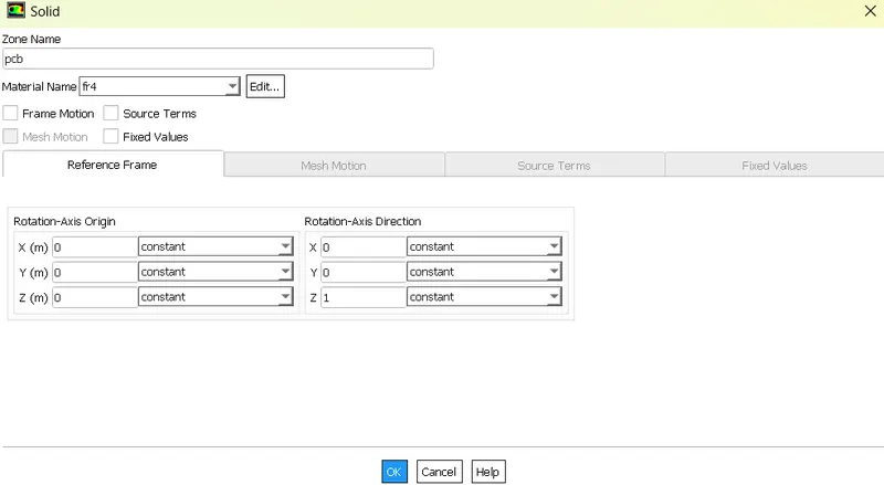
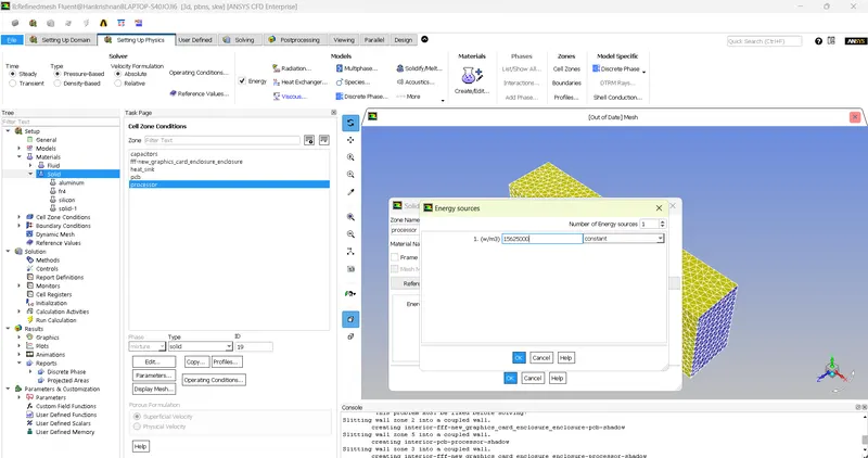
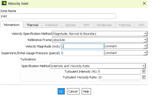
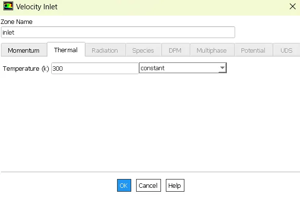
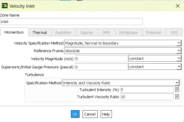
- Now assign boundary conditions. Inlet with 1m/s and temperature of 300K.
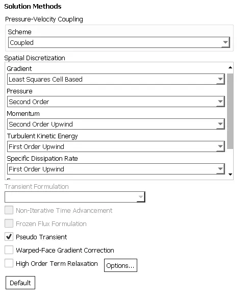
- Pressure velocity coupling was changed to Coupled mode from Simple mode and reference variables were changed.
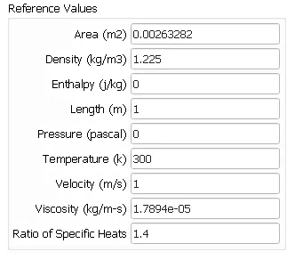
- Set the residuals and hybrid initialize.
- Run Calculation.
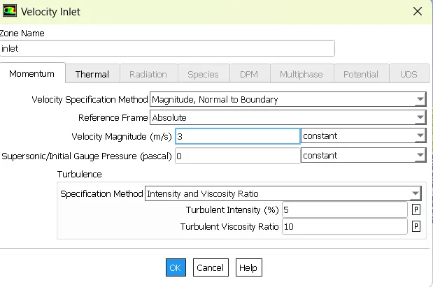
- Repeat the same for 1m/s refined mesh and 3m/s and 5m/s. Only change in solver settings for these velocities are in boundary inlet conditions.
POST PROCESSING
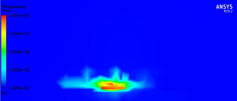
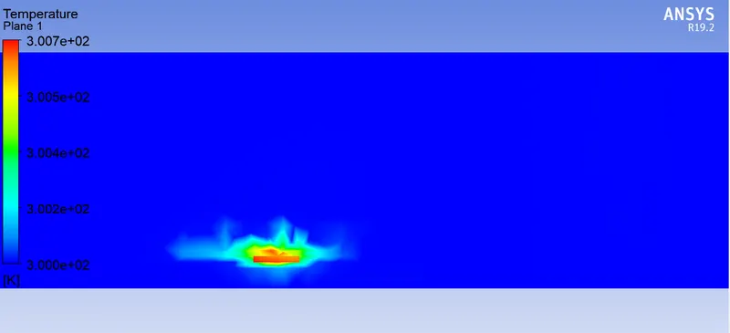
- Create a plane and obtain temperature contour
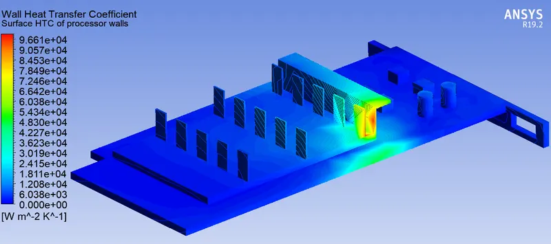
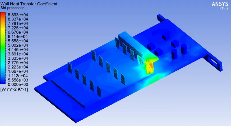
- Obtain surface heat transfer contour for whole body.
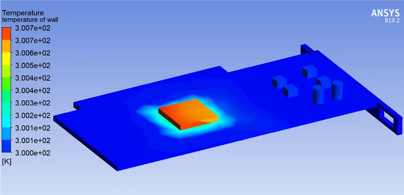
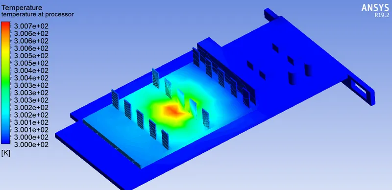
- Obtain Temperature contour for Entire graphics card.
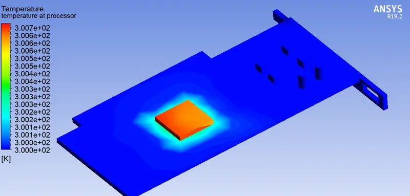
- Obtain temperature contour including all parts except heat sink to see the temperature of processor.
RESULT:
CASE:1 Baseline mesh with 1m/s Air flow
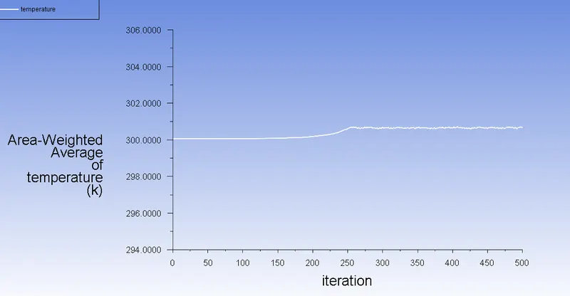
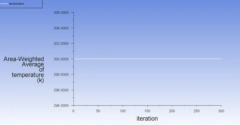
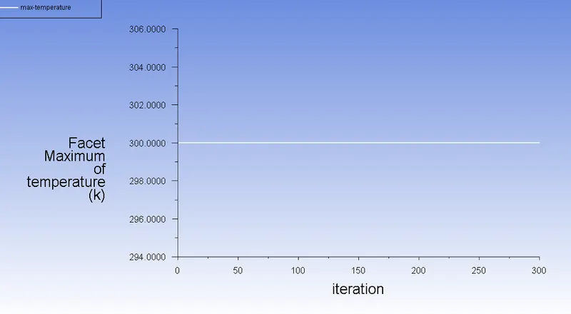
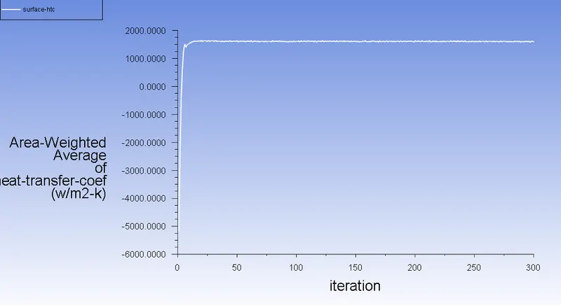
Residuals, average temperature, facet maximum temperature and average heat transfer coefficient plots.
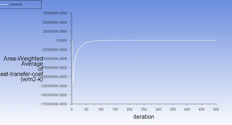
Parameters chart

Plane temperature contour
Surface Heat transfer contour
Temperature contour with heat sink
Temperature contour without heat sink
CASE:2 Refined mesh with 1m/s Air flow
Residuals, average temperature, facet maximum temperature and average heat transfer coefficient plots.
Parameters chart

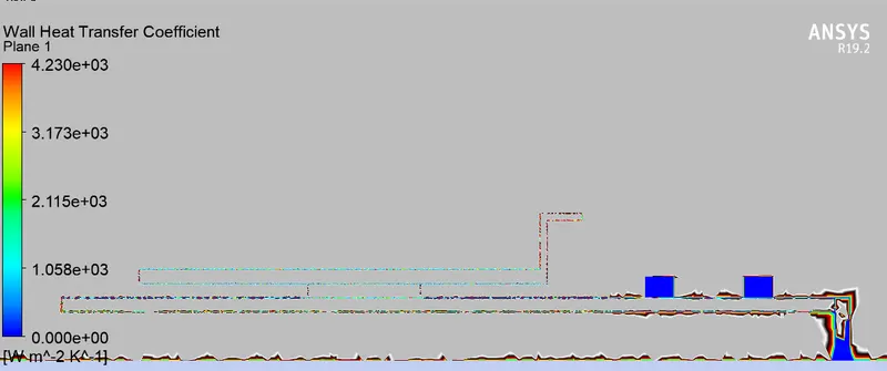
Surface Heat transfer contour
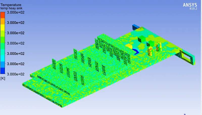
Temperature contour with heat sink
CASE:3 3m/s Air flow
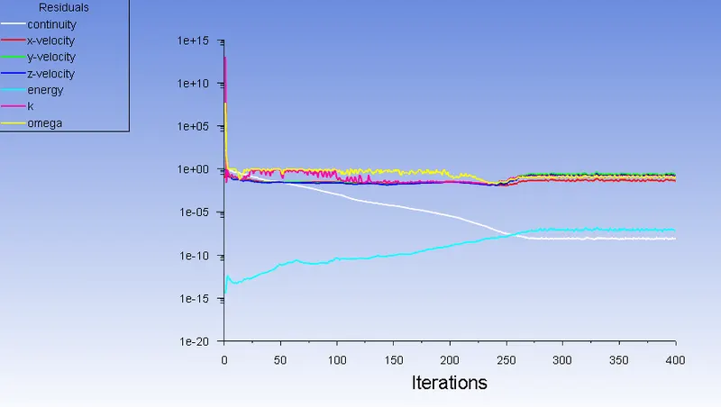
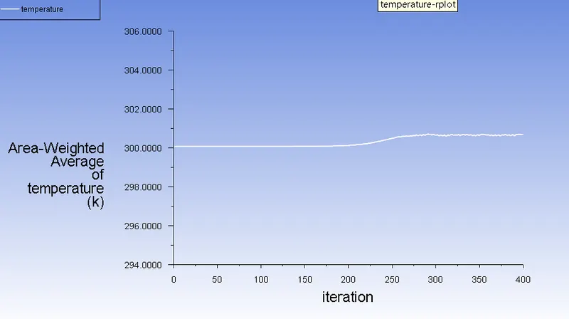
Residuals, average temperature, facet maximum temperature and average heat transfer coefficient plots.
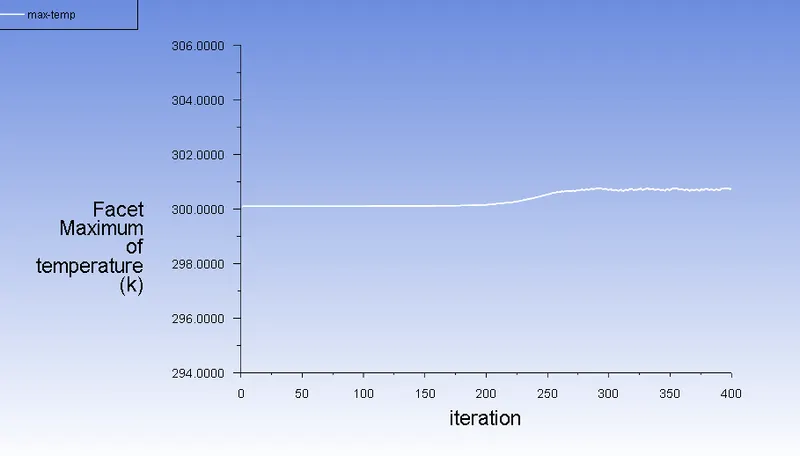
Parameters chart

Plane temperature contour
Surface Heat transfer contour
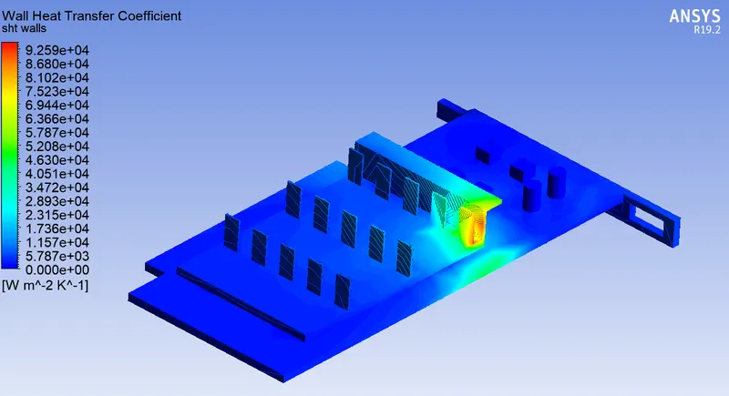
Temperature contour with heat sink
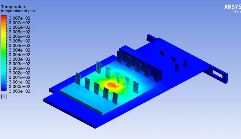
Temperature contour without heat sink
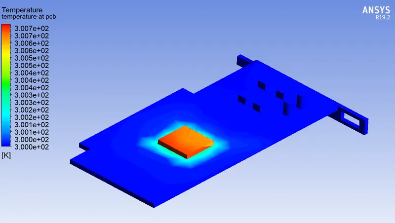
CASE:4 5m/s Air flow
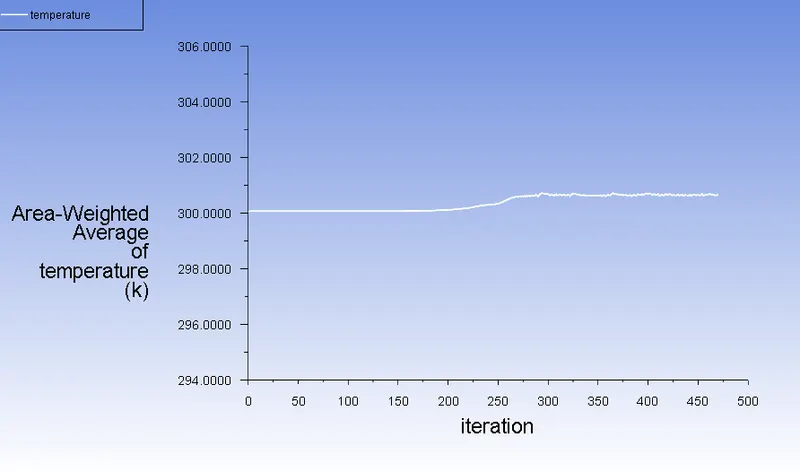
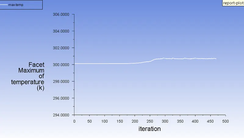
Residuals, average temperature, facet maximum temperature and average heat transfer coefficient plots.
Parameters chart

Plane temperature contour
Surface Heat transfer contour
Temperature contour with heat sink
Temperature contour without heat sink
CONCLUSION:
It was noted that in baseline mesh itself the mesh elements were refined and for further refinement the entire model was further dicretized to finer meshes. The refined mesh wasn't giving much change in average and maximum temperature readings as compared to baseline mesh. But in refined mesh there was change in wall heat transfer coefficient as it became a positive value. This way grid dependency check was carried out.
Potential hotspots were obtained on heat sink and processor from post processed results.
REFERENCES: