Week 6 - CHT Analysis on a Graphics card
AIM:
- To perform the steady state CHT simulation on a graphics card model
- To check the various difference occurs as we change the velocity of incoming air
Theory-
The Conjugate Heat Transfer (CHT) analysis type allows for the simulation of heat transfer between solid and fluid domains by exchanging thermal energy at the interfaces between them. Typical applications of this analysis type exist as, but are not limited to, the simulation of heat exchangers, cooling of electronic equipment, and general-purpose cooling and heating systems.
Procedure-
import the geo to space claim use the shared topo option
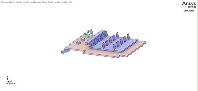
as we can see there are multiple components-
1)processor
2)heat sink
3)pcb
Meshing-
inserting edge sizing on graphic card (1mm)
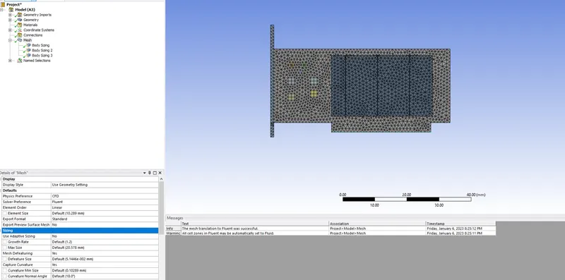
rest fluid volume is coarse at 10mm edge size
total no of cells 165434
Solution-
Heat generation calculation:
assuming heat generated by TDP = 1WATT
VOL OF PROCESSOR = 64MM2
Q=1562500Watt/m3
Materials-
1)Heat sink - Aluminium
Density = 2719 Kg/m^3
Heat capacity = 871 J/Kgk
Thermal conductivity = 202.4 W/mK
2) Processor – Silicon
Silicon is not available in fluent database so a material is created manually
Density = 2000kg/m^3
Heat capacity = 710J/KgK
Thermal Conductivity = 150W/mK
3) PCB
Density = 700kg/m^3
Heat capacity = 2310 J/KgK
Thermal Conductivity = 0.17W/mK
4) Fluid – Air
Density = 1.225 kg/m^3
Heat capacity = 1006.43 j/KgK
Thermal Conductivity = 0.0242 W/mK
Setup-
Solver type: pressure based
Steady state solver
Energy equation is on
Turbulent model : K-Omega SST Model
assigning heat source-
cellzones>processor>assign material silicon> input source term>constant>enter value(q/m3)
hybrid initialize
RESULTS-
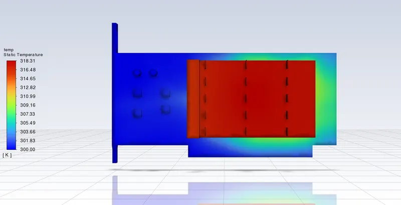
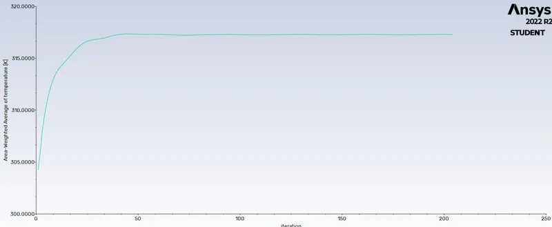
CASE 1 inlet vel = 3m/s
temp plot-
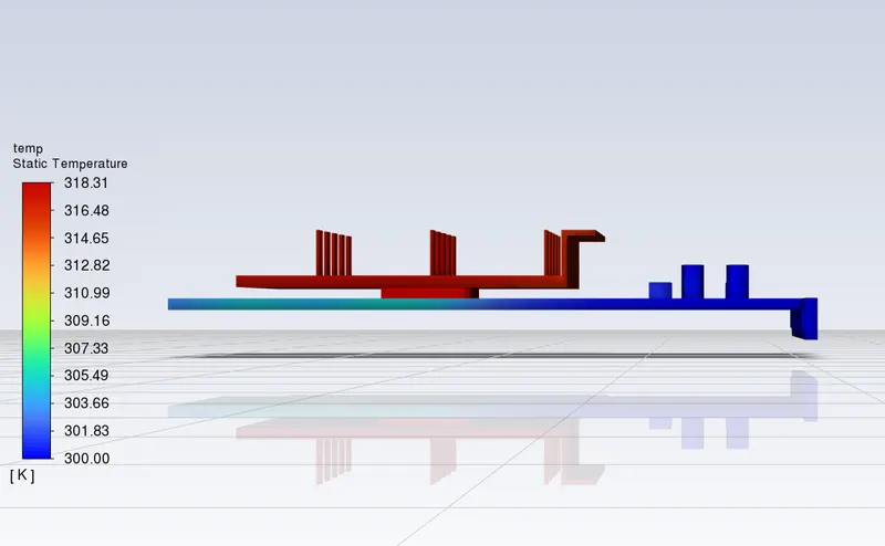
temp of heat sink plot-
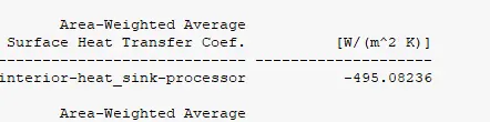
heat transfer coeff at processor -
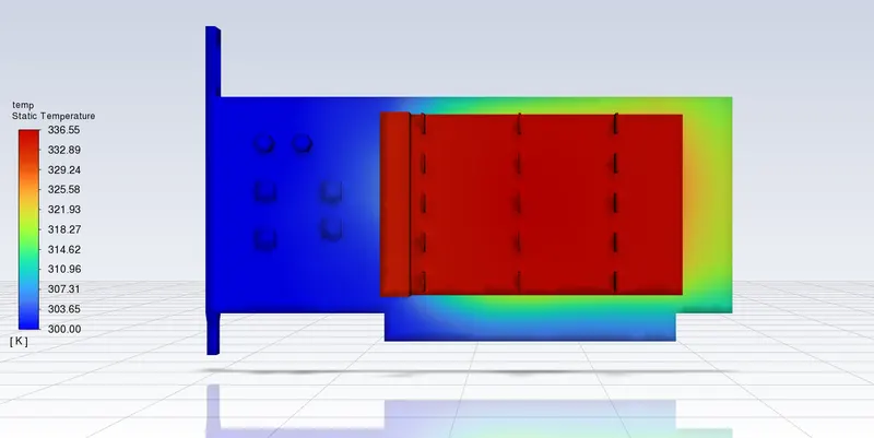
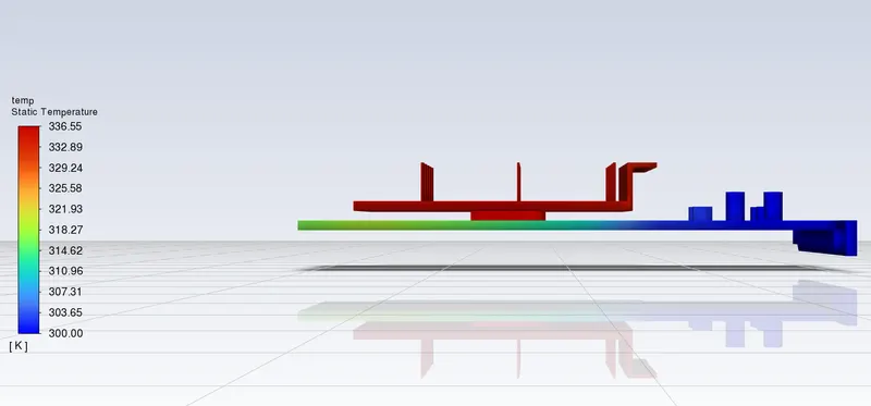
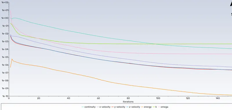
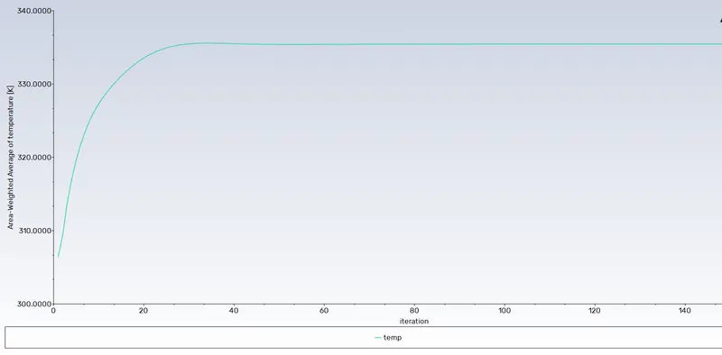
Case 2 inlet vel 1m/s-
temp contour-
residual plots-
heat sink temp plot-
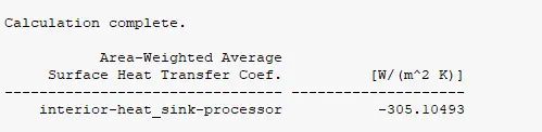
heat transfer coef-
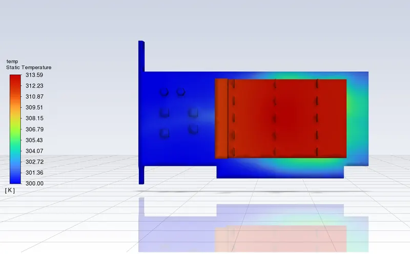
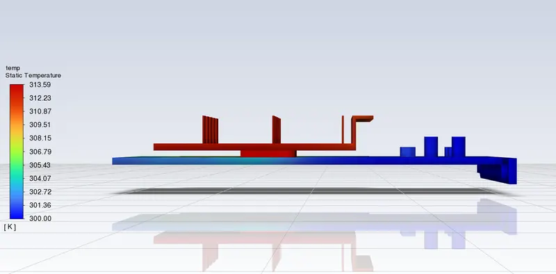
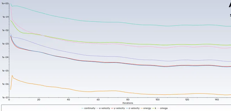
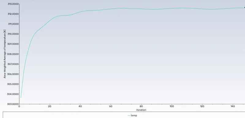
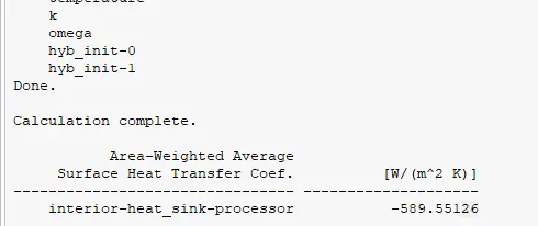
Case 3 inlet vel 5m/s-
temp contour-
residual plots-
heat sink temp plot-
heat transfer coeff-
| SR NO. | Inlet velocity (m/s) | heat transfer coeff(w/m2k) | Maximum temperature attained |
| 1 | 3 m/s | -495 | 318.4 K |
| 2 | 1 m/s | -305 | 335.3 K |
| 3 | 5 m/s | -589 | 313.9 K |
From this we can conclude that as inlet velocity get increased ....heat generated get decreased.