Week 6 - CHT Analysis on a Graphics card
Aim.
Perform a steady-state conjugate heat transfer analysis on a model of a graphics card. You can use appropriate materials of your choice for the simulation. Make sure to properly define the correct solid and fluid zones. Refer the video for further clarification and the model is provided below the video.
Run the simulation for best possible mesh with combination of coarse and refined mesh in different regions. Explain the reason for choosing the particular mesh settings.
Objective
- To Run the simulation by varying the velocity from 1m/sec to 5m/sec for at least 3 velocities and discuss the results.
- To Find out the maximum temperature and heat transfer coefficient attained by the processor.
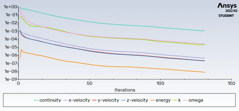
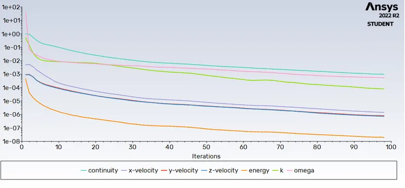
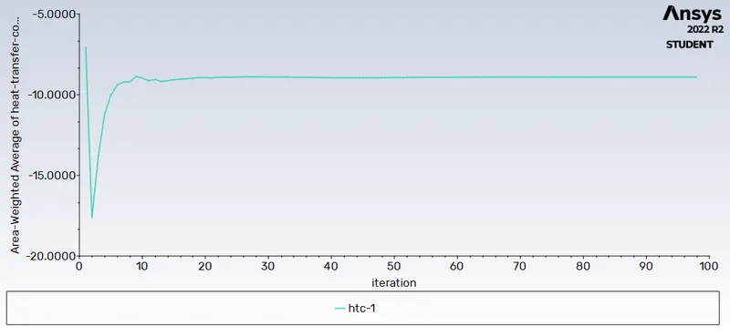
- To Prove that the simulation has achieved convergence with appropriate images and plots.
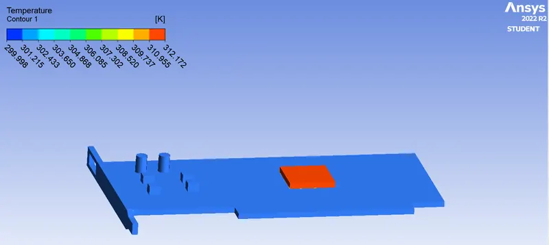
- To Identify potential hotspots on the model.
Conjugate Heat Transfer (CHT)
The Conjugate Heat Transfer (CHT) analysis type allows for the simulation of heat transfer between solid and fluid domains by exchanging thermal energy at the interfaces between them. Typical applications of this analysis type exist as, but are not limited to, the simulation of heat exchangers, cooling of electronic equipment, and general-purpose cooling and heating systems.
Some Examples of CHT are :
HVAC, Heat Exchanger, Tank, Internal Combustion Engine, Heat Sink, Boiler, Reactor, Heat Pipe, Turbocharger
CHT analysis type allows for the simulation of the heat transfer between the solid and liquid domains by exchanging thermal energy at the interface between them. The simulation of the heat exchangers, cooling of the electronic equipment, and general-purpose cooling and heating system. In the case of CHT that is being done in this project, we have the convection mode of heat transfer between the fluid and the solid aluminum wall of the exhaust pipe and then the conduction mode of heat transfer is followed within the wall of the exhaust pipe wall.
Objective 1
Run the simulation by varying the velocity from 1m/sec to 5m/sec for at least 3 velocities and discuss the results.
Procedure.
- Geometry
- Import Graphics card model in space claim.
- Turn on the shared topology to get a conformal mesh.
- Meshing
- Set the base mesh to check every thing is working fine or not.
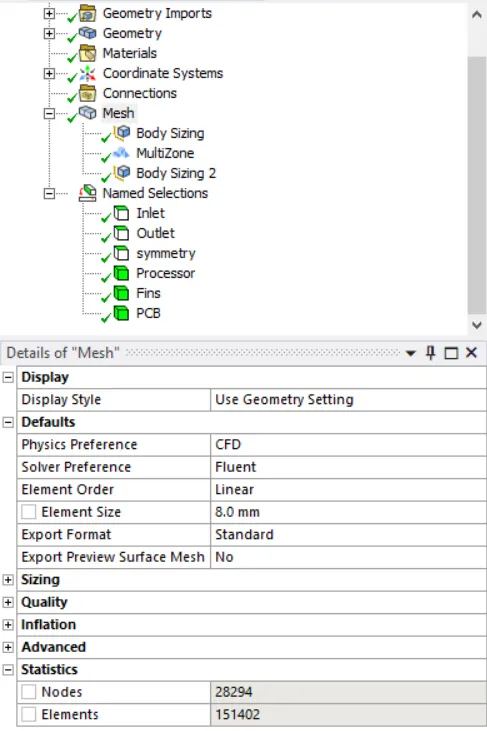
- Refine the mesh size to 8 mm for computational domain.
- Add body sizing for the fins and PCB board, Mesh size =1mm
- Change method to Multizone (It automatically generates a pure hexahedral mesh where possible and then fills the more difficult to capture regions with unstructured mesh.)
- Do the name selection for inlet, outlet, symmetry wall, fin, PCB and Processor
- Setup
- Pressure based solver is used with steady state condition.
- Energy equation, k-omega viscus model is used.
- Set the boundary conditions for inlet i.e. Velocity 1 m/s ,3m/s and 5m/s
- average weighted plots for Average temperature, Heat transfer coefficient and Max temperature.
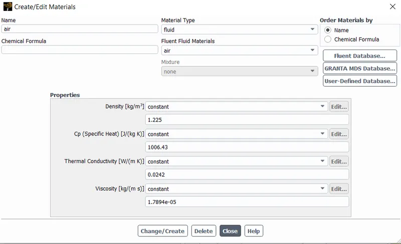
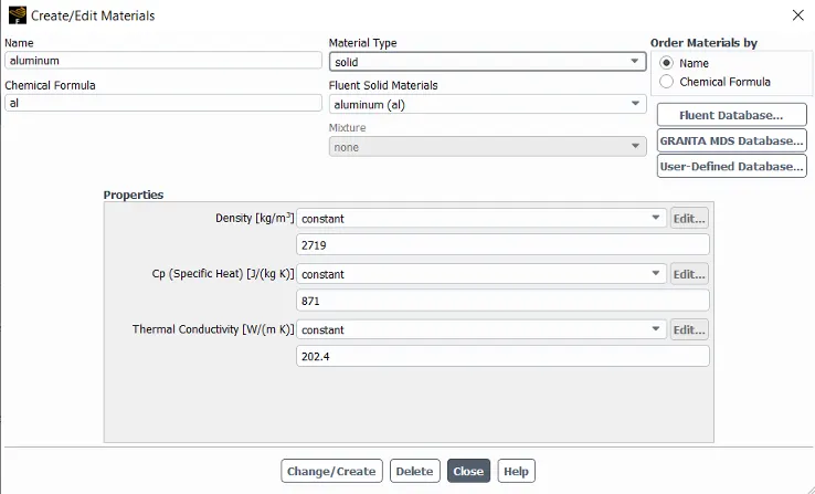
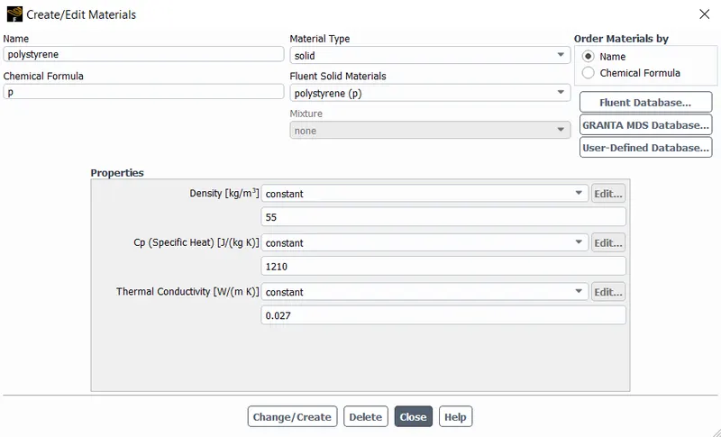
- Define material for all components of graphic cards.
- Air for computational domain
- Aluminum for fins.
- Polystyrene for PCB.
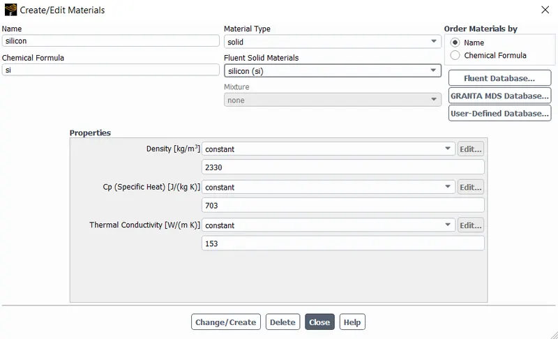
- Silicon for Processor
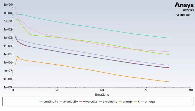
Simulation 1. Inlet Velocity 1 m/s
Residual Chart
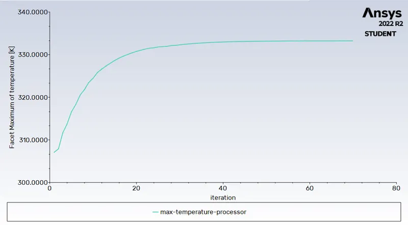
Solution converged in 70 iteration .
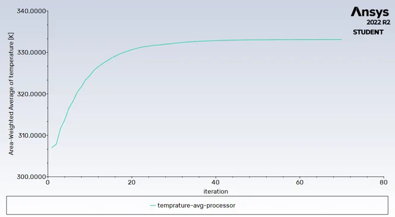
Average temperature.
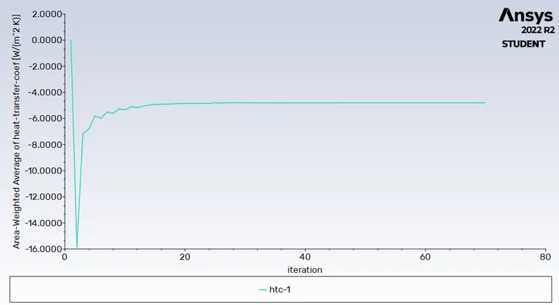
Heat transfer coefficient
Max Temperature.
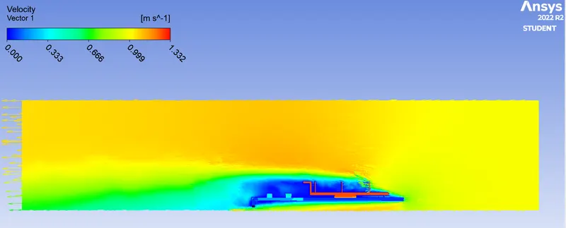
Velocity contour
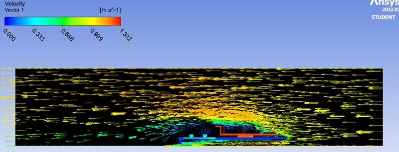
Vector
Simulation 2. Inlet Velocity 3 m/s
Residual
Max Temperature
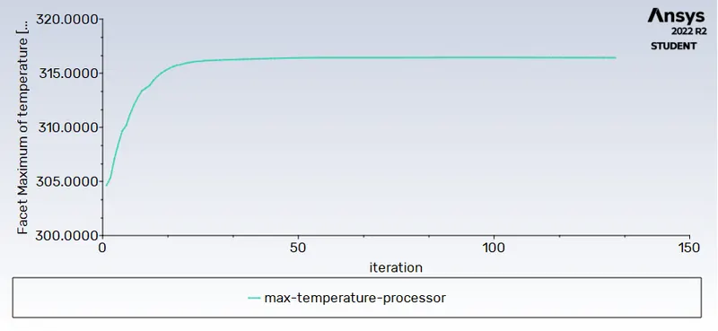
Average Temperature.
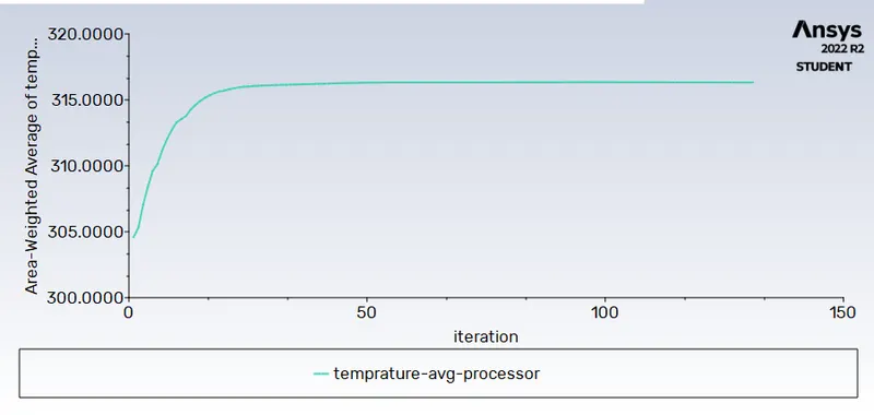
Heat Transfer Coefficient
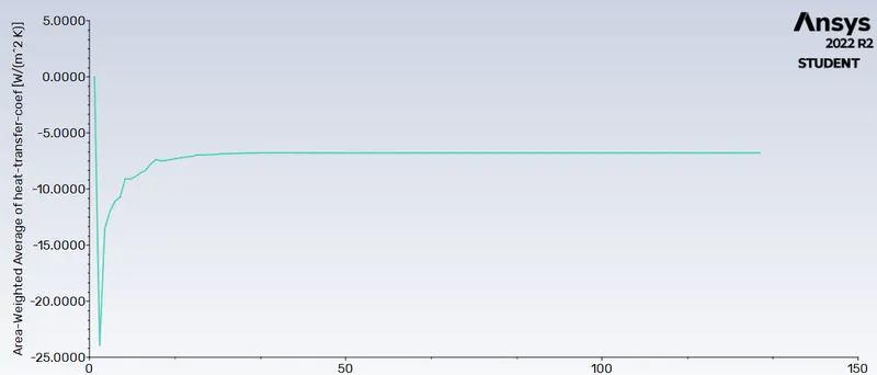
Velocity Contour
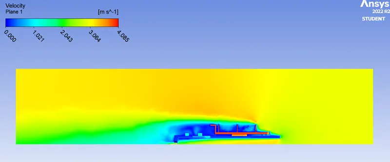
Vector
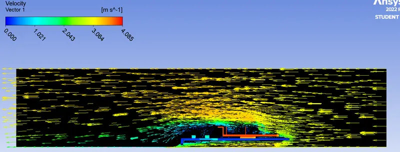
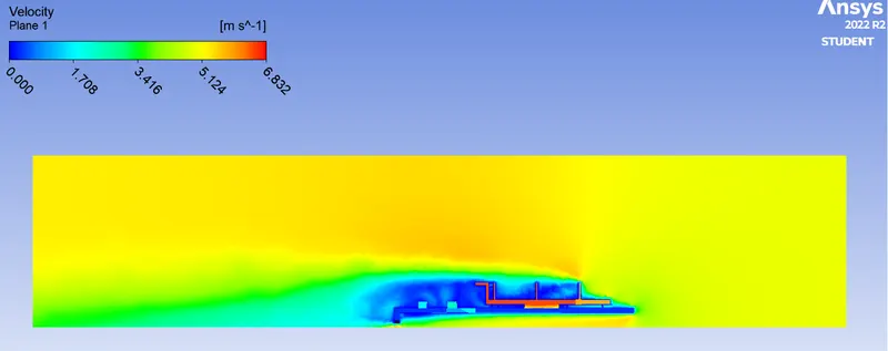
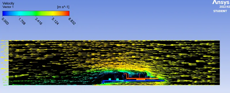
Simulation 3. Inlet Velocity 5 m/s
Residual
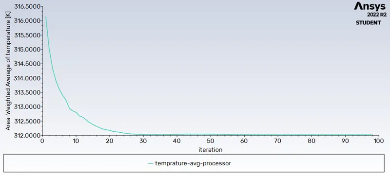
Average Temperature.
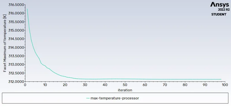
Max Temperature
Heat Transfer Coefficient
Velocity Contour
Vector
MESH INDEPENDENCE STUDY
|
Mesh Size |
Velocity |
Avg. temperature |
HTC |
Max. Temperature |
Convergence |
|
Computational domain=8mm PCB and Fins =1mm |
1m/s |
333.070 |
-4.583 |
333.193 |
70 iteration |
|
Computational domain=8mm PCB and Fins =1mm |
3m/s |
316.13 |
-6.78 |
316.4 |
131 iteration |
|
Computational domain=5mm PCB and Fins =1mm |
5m/s |
312.02 |
-8.91 |
312.13 |
98 iteration |
Potential hotspots on the model.
CONCLUSION
In our experiments, we increased the air inlet velocity to study the effects of cooling on the processor. From the results, we can see that the processor is the main heat source of a graphic card, which is extremely hot when operating. A higher inlet velocity in the air inlets leads to a lower temperature for the processor. Therefore a higher air velocity in the air inlet results in more efficient cooling of the processor.
As we know, the heat transfer coefficient expresses the amount of heat transferred between a fluid and a solid surface by convection. The larger the heat transfer coefficient, the more heat transfer occurs. Another factor that greatly influences the magnitude of the heat transfer coefficient is the fluid flow velocity over the object surface. Therefore, higher the inlet velocity, the larger the heat transfer coefficient.