Week 2 - Flow over a Cylinder.
1. AIM: Simulate the flow over a cylinder and explain the phenomenon of Karman vortex street.
2. OBJECTIVE:
PART-I
- Simulate the flow with the steady and unsteady case and calculate the Strouhal Number for Re= 100.
PART-II
- Calculate the coefficient of drag and lift over a cylinder by setting the Reynolds number to 10,100,1000,10000 & 100000. (Run with steady solver)
- Discuss the effect of Reynolds number on the coefficient of drag. [ Results should be validated with any standard literature and error should be within 5 %]
Results:-
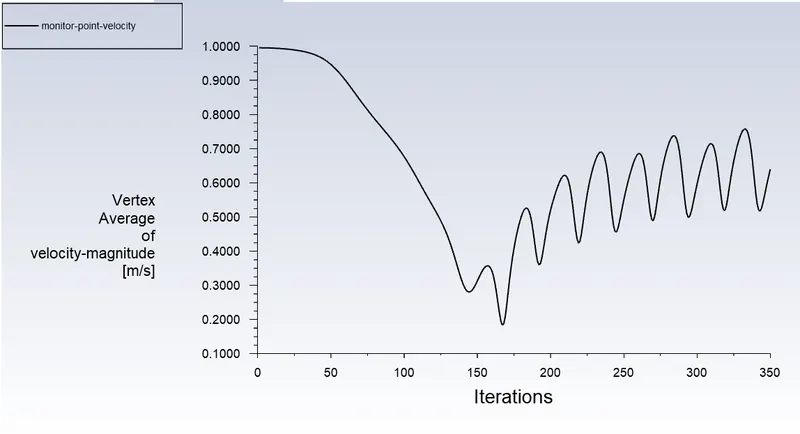
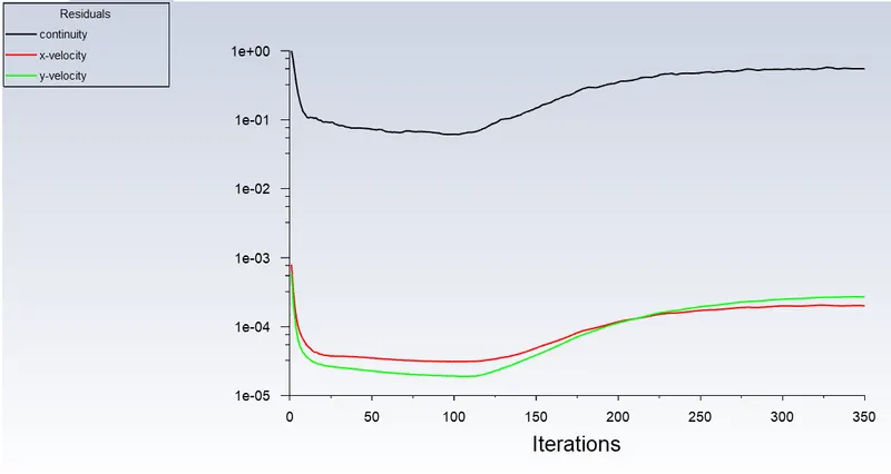
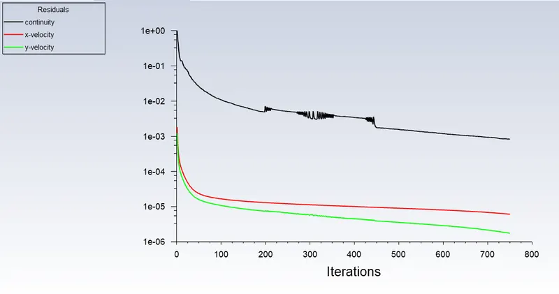
- In both approaches, show that the flow has converged. That is, what quantities or plots need to be looked at to determine that the flow has converged?
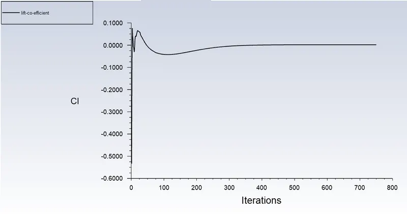
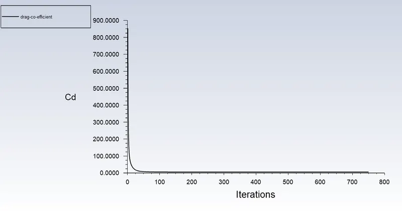
- Plots of the coefficient of drag and lift.
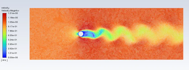
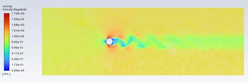
- Plots to show vortex shedding behind the cylinder.
3. THEORY AND GOVERNING EQUATION::
- Flow over cylinder- Analyzing the flow over a cylinder to study the effects of shedding of vortex in Steady as well as the transient state.
- Vortex shedding- Vortex shedding is an oscillating flow that takes place when a fluid such as air or water flows past a bluff (as opposed to streamlined) body at certain velocities, depending on the size and shape of the body. In this flow, vortices are created at the back of the body and detach periodically from either side of the body forming a Karman Vortex street.
- Karman Vortex street- A Karman vortex street is a repeating pattern of swirling vortices, caused by a process known as Vortex shedding, which is responsible for the unsteady seperation of flow of a fluid around blunt bodies.
-
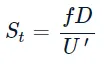
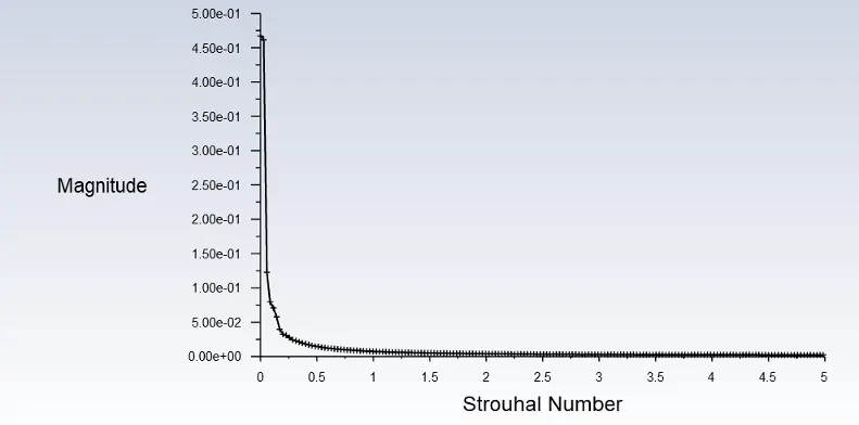
Strouhal number- In dimensional analysis, the Strouhal number is a dimensionless number describing oscillating flow mechanisms. For large Strouhal numbers (order of 1), viscosity dominates fluid flow, resulting in a collective oscillating movement of the fluid "plug". For low Strouhal numbers (order of 10−4 and below), the high-speed, quasi-steady-state portion of the movement dominates the oscillation. Oscillation at intermediate Strouhal numbers is characterized by the buildup and rapidly subsequent shedding of vortices.
The Strouhal number is often given as-
Where,
f= frequency of vortex shedding
D= characteristic diameter of the cylinder
U'= fluid flow velocity
e. Co-efficient of drag- In fluid dynamics, the drag coefficient(Cd) is a dimensionless quantity that is used to quantify the drag or resistance of an object in a fluid environment.
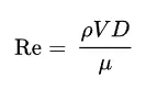
f. Reynolds number- The Reynolds number is a measure of the ratio of inertial to viscous forces in the flow of a fluid and may be defined as:
Where,
mu= fluid dynamic viscocity in kg/(m.s)
V = fluid velocity in m/s
rho = fluid density in Kg/m^3
D = Cylinder diameter
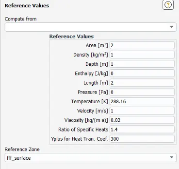
Reference value
4. BODY OF CONTENT:
- PROCEDURE-
-
Geometry-
- Open spaceclaim and create a geometry.
- After creating geometry close the spaceclaim and open mesh for mesh setting.
- Mesh-
- To start meshing setting click on the mesh and then on the update so that the geometry information gets updated.
- Open mesh by double clicking.
- Default mesh is quadrilateral dominating mesh which is not suitable.
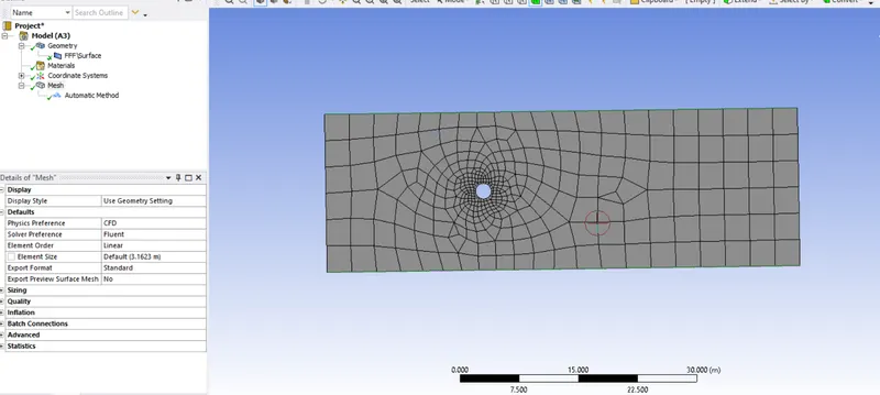
iv. Change the mesh type to triangular.
- Click on mesh>insert>method.
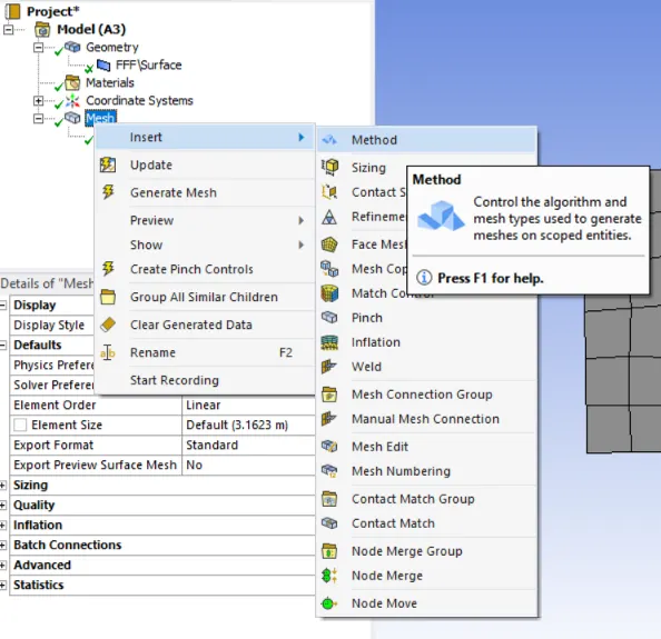
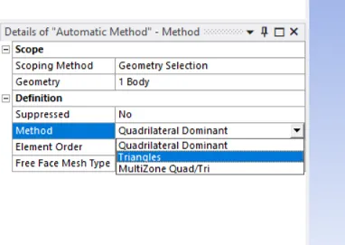
- Select the geometry and with surface/body selection tool and apply. And then select triangular mesh from the drop down menu.
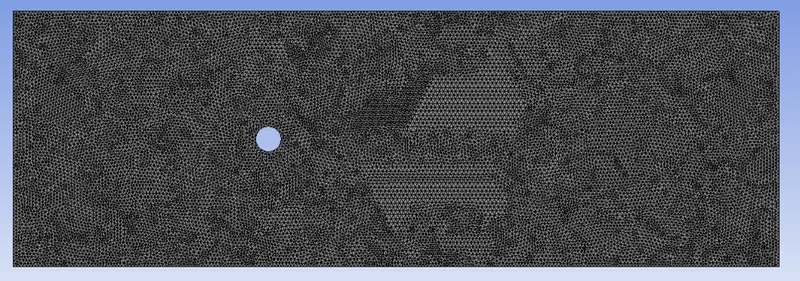
- Change the element size to desired value in our case we are using an element size of 0.25m. Update the mesh to get results (in actually mesh size should be changed on the basis of results obtained, change case by case to figure it the best mesh).
-
Geometry on which flow calculation is carried must be smooth and captured perfectly, in our case the cylinder is not in perfect shape.
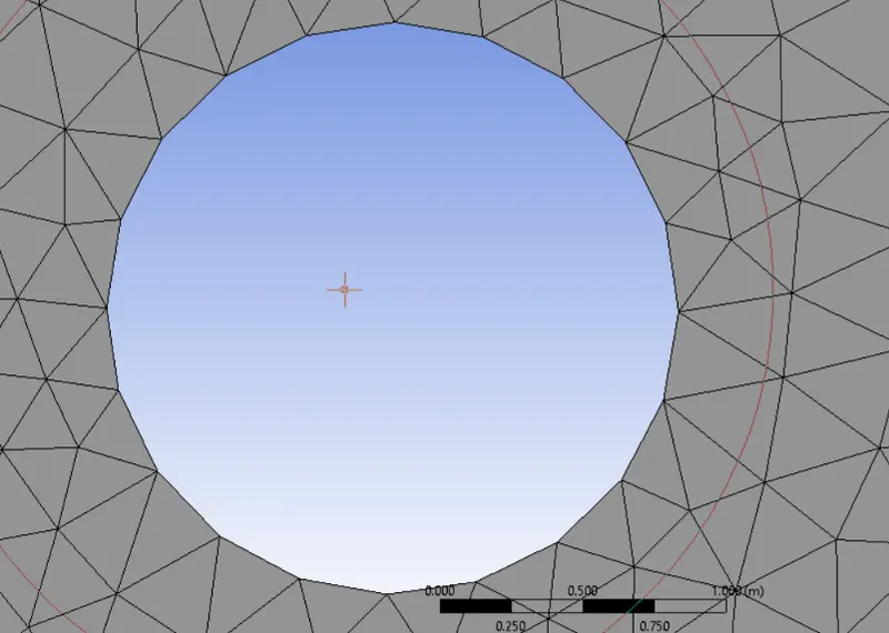
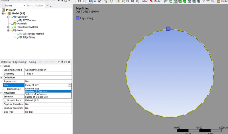
- To get the perfect shape or shape which will provide minimum deviation we will divide the edge of the circle into 36 section.
- Click on mesh>insert>sizing
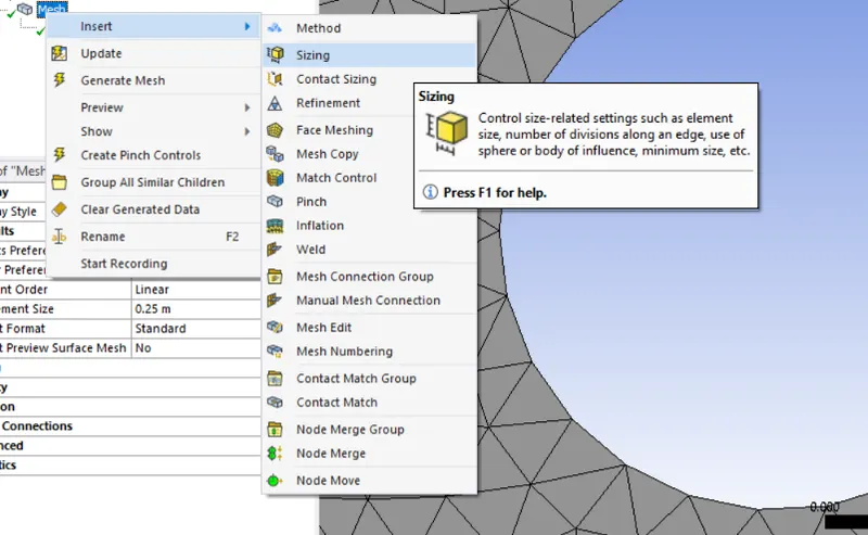
-
Select type and then number of divisions , enter the value as 36 divisions
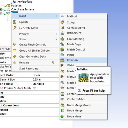
- Create an inflation layer
- Click on mesh>insert>inflation layer
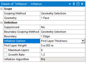
- Select face and for geometry and then shape that is edge of the circle for boundary conditions select inflation option as first layer, max layers 6
- Generate the mesh to get the results.
- Click on mesh>insert>inflation layer
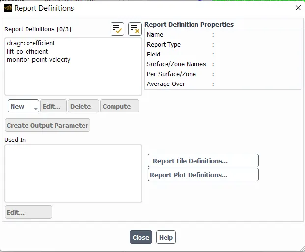
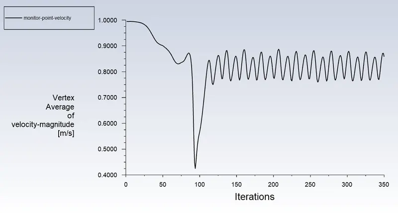
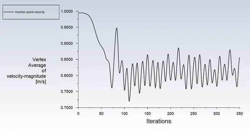
c. Create a Vertex average of velocity magnitude using surface report at a monitor point 8m away from the center of the cylinder to the right of the cylinder along X-direction.
to read a average velocity value at above monitor point go to definations - surface report - vertex average.
Coefficient of Drag and Coefficient of Lift report created using force report.
For drag go to definations - new - force report - Drag
For lift go to definations - new - force report - Lift.
Reference value
- SOLUTION-
Part-I-
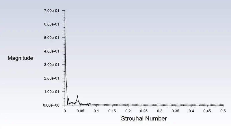
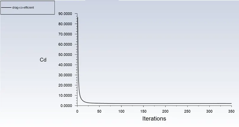
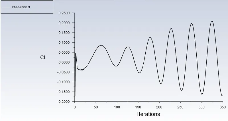
- Simulate the flow with the steady case and calculate the Strouhal Number for Re= 100.
Strouhal Number-
Coefficient of Drag-
Coefficient of Lift-
Vertex average-
Residual
Velocity Contour-
Simulate the flow with the unsteady case and calculate the Strouhal Number for Re= 100.
Strouhal Number-
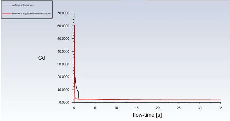
Coefficient of Drag-
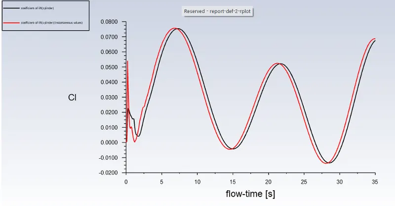
Coefficient of Lift-
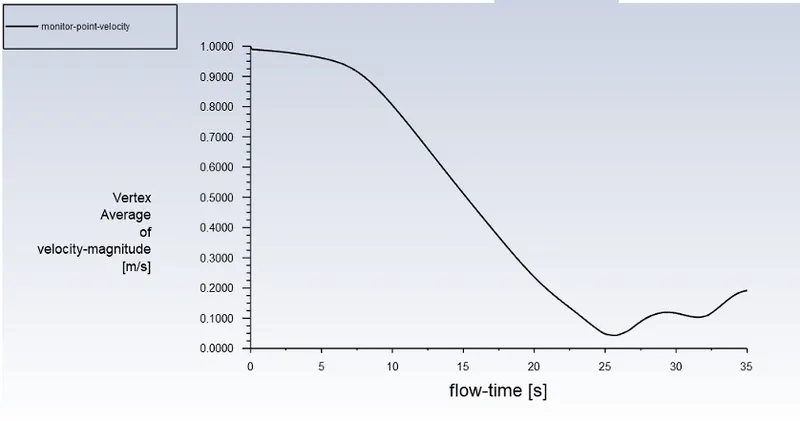
Vertex average-
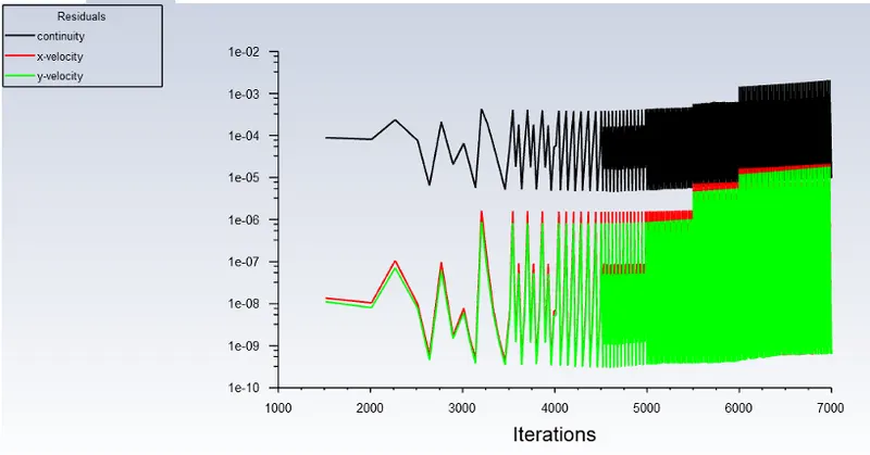
Residual-
Velocity Contour-
Part-II
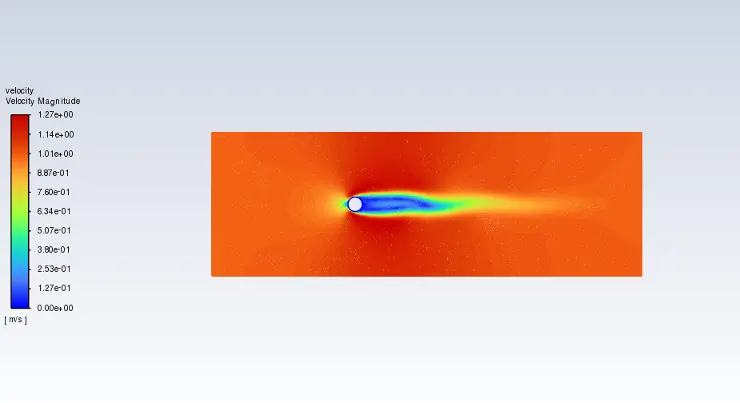
- Simulate the flow with the steady state for Re= 10.
Residual-
Coefficient of Lift-
Coefficient of Drag-
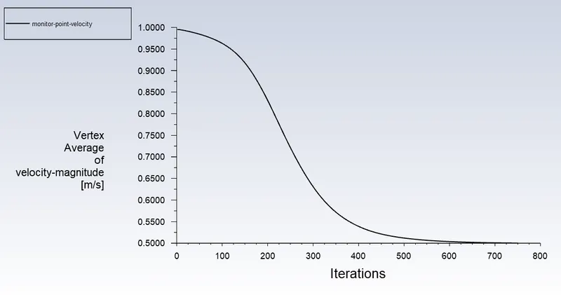
Vertex average-
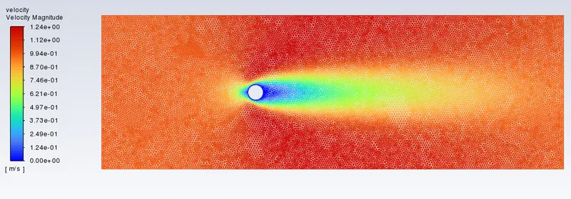
Velocity Contour-
- Simulate the flow with the steady state for Re= 1000.
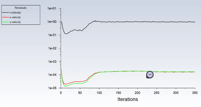
Residual
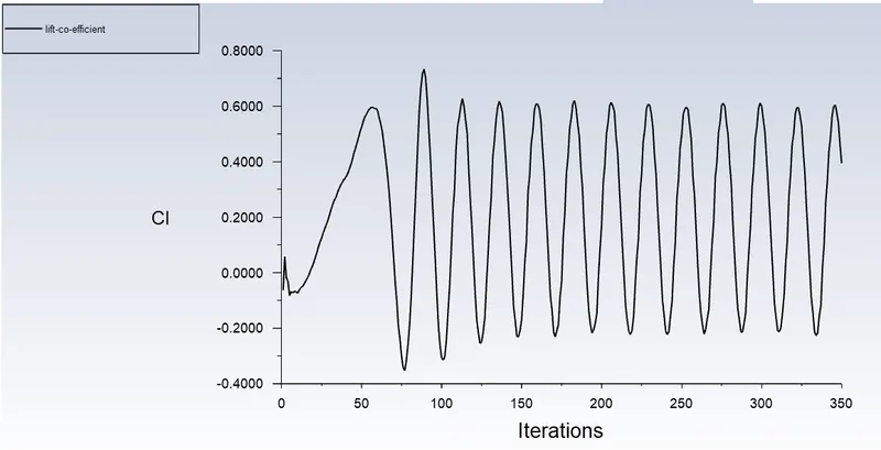
Coefficient of Lift-
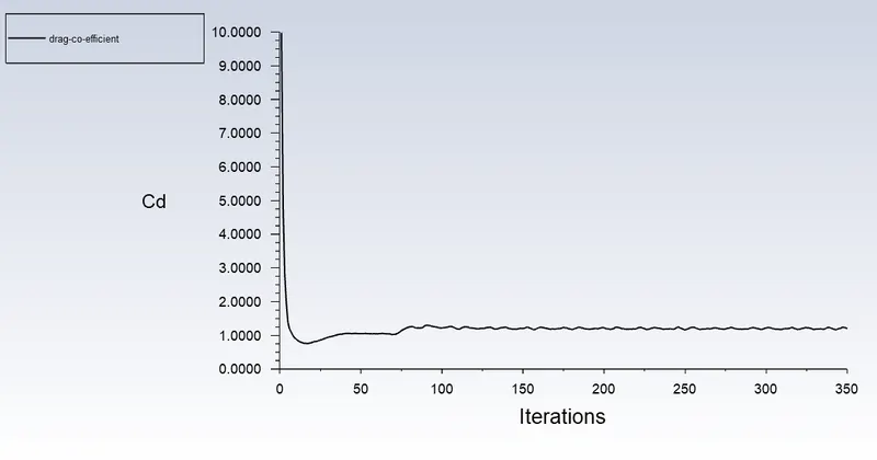
Coefficient of Drag-
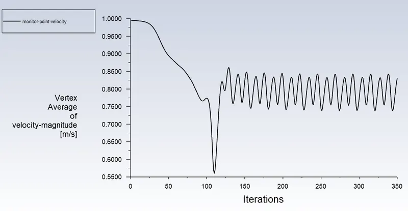
Vertex average-
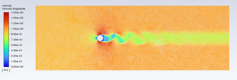
Velocity Contour-
- Simulate the flow with the steady state for Re= 10000.
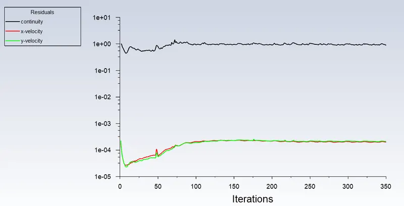
Residual-
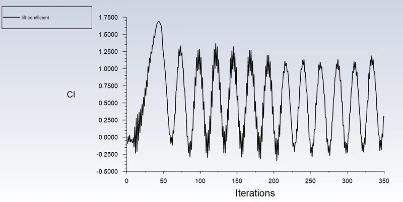
Coefficient of Lift-
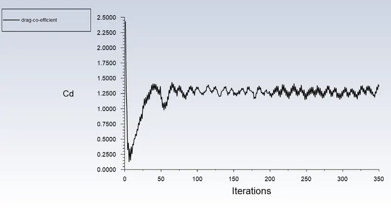
Coefficient of Drag-
Vertex average-
Velocity Contour-
- Simulate the flow with the steady state for Re= 100000.
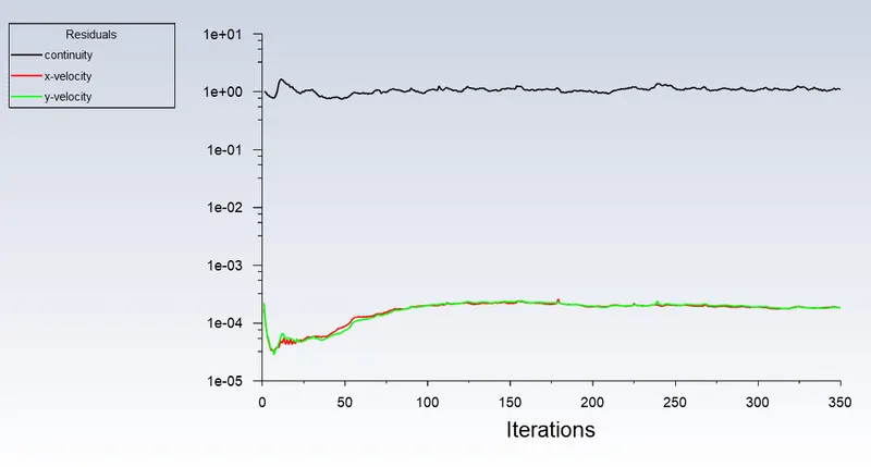
Residual-
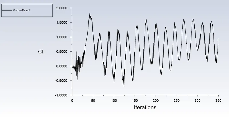
Coefficient of Lift-
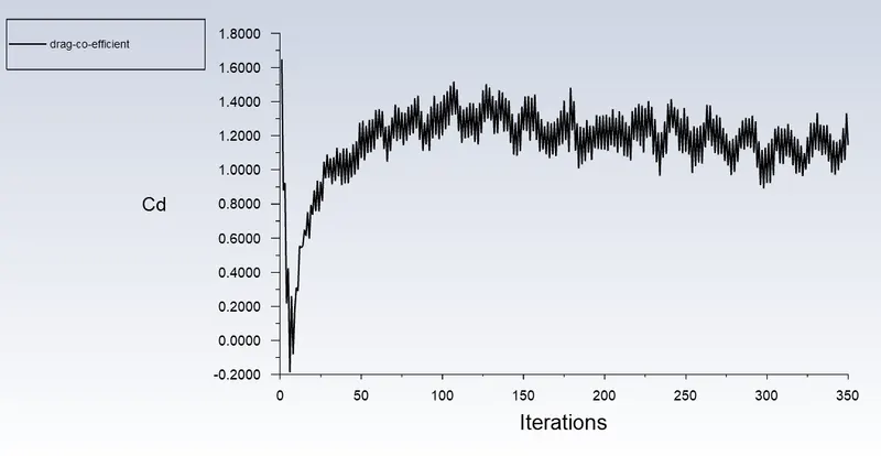
Coefficient of Drag-
Vertex average-
Velocity Contour-
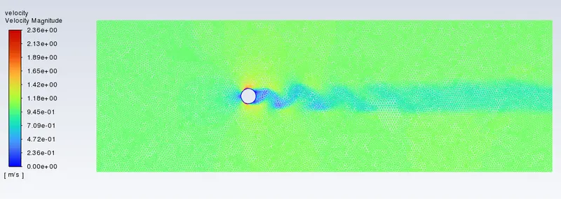
- Convergence
When your simulation has no change on all the convergence criteria, after certain iterations or timesteps, then we can consider that the solution has reached a steady-state, i.e., converged.
5. RESULT:
Values of the coefficient of drag and lift coefficient for respective Reynolds number is tabulated as follows:
| Reynolds Number | Coefficient of drag | Lift coefficient |
| 10 | 5.4279647 | 0.001487367 |
| 100 | 2.175162 | -0.16877345 |
| 1000 | 1.1994432 | 0.39361719 |
| 10000 | 1.3604293 | 0.29220943 |
| 100000 | 1.1447219 | 0.92692326 |
6. CONSLUSION:
1. When fluid flows over the cylinder, wake region is formed next to cylinder due to decrease in pressure and recirculation of flow occures and hence flow separation occures.
2. As flow over cylinder is being transient meaning time dependent phenomenon, we are unable to observe flow separation at low reynolds no.
3. In this assignment we have kept all parameters constant and have only varried velocity to change reynolds number. So as the reynolds no. increases coefficient of drag decreases.however after reynolds no. = 4000, flow is turbulent and hence coefficient of drag is lower.