Week 6 - CHT Analysis on a Graphics card
CHALLENGE REPORT :
AIM :
To Perform a steady-state conjugate heat transfer analysis on a model of a graphics card.
OBJECTIVE :
To perform a steady-state conjugate heat transfer analysis on a model of a graphics card. Selecting the proper mesh size by performing the grid independent study. Assumptions are made for the selection of material along with their properties which is suitable for the given model based on some reach paper. The simulation is proceed by varing the inlet velocity of air from 1m/sec to 5m/sec for at least 3 velocities and analysing the obtained results. The results obtained for three velocities should be compared by creating the contours and plots. The maximum temperature and heat transfer coeficient between the graphics card and the surrounding air is to be obtained as the output results and changes should be study and flow analysis is to be carried out. The potential hotspots is identified by using the temperature contours and explained the details.
THEROEY :
HEAT TRANSFER COEFFICIENT :
The heat transfer coefficient is the proportionality constant between the heat flux and the thermodynamic driving force for the flow of heat (i.e., the temperature differance, ΔT ). It is used in calculating the heat transfer, typically by convection or phase transition between a fluid and a solid. The heat transfer coefficient has SI unit in watts per square meter kelvin (W/m2/K).
The general definition of the heat transfer coefficient is:
h=q/ΔT
The three main modes of heat transfer:
* Conduction is heat transfer that occurs when a temperature difference exists across a stationary medium.
* Convection is the heat transfer between a surface and a moving fluid when there is a temperature difference between the two.
* Radiation(thermal radiation) is the emission of energy in the form of electromagnetic waves. In the absence of an intervening medium ,there is net heat transfer by radiation between two surfaces at different temperatures.
CONJUGATE HEAT TRANSFER :
Conjugate heat transfer is a type of heat transfer analysis between solids and fluid(s). This type of heat transfer includes both convection (between fluids) and conductive (between solids) heat transfer, as well as both forced and natural convection.
Typical applications of this analysis type exist as, but are not limited to, the simulation of heat exchangers, cooling of electronic equipment, and general-purpose cooling and heating systems.
Some common examples where conjugate heat transfer analysis if performed are :
* Heat exchanger analysis :
Consider a shell and tube heat exchanger where heat from the fluid at high temperature is transferred to the fluid at low temperature. In the process, heat gets transferred from hot fluid to the walls of the tubes and to the cold fluid. The processes happeining here are convective heat transfer from hot liquid to the walls, conductive heat transfer from face of the wall in contact with the hot fluid and convective heat transfer from other face of the wall to the cold fluid.
* Heat sink :
A heat sink is a passive heat exchanger that transfers the heat generated by an electronic or a mechanical device to a fluid medium, often air or a liquid coolant, where it is dissipated away from the device, thereby allowing regulation of the device's temperature. In computers, heat sinks are used to cool CPUs, GPUs and some chipsets and RAM modules. Heat sinks are used with high-power semiconductor devices such as power transistors and optoelectronics such as lasers and light emitting diodes (LEDs), where the heat dissipation ability of the component itself is insufficient to moderate its temperature.
LAWS AND FORMULA USED :
* Law of thermal conductivity,
Q = -k*A*(dt)/(dx)
where,
h ---> Heat transfer coefficient,
k ---> Thermal conductivity,
A ---> Area.
* Newton's law of cooling ,
Q = h*A*Delta(t)
where,
h ---> Heat transfer coefficient,
A ---> Area.
* Thermal diffusivity,
alpha =k*/(rho*Cp)
where,
k ---> Thermal conductivity,
rho ---> Density,
Cp ---> specific heat capacity.
* Nusselt Number,
Nu= convective heat transfer / conductive heat transfer
=h/(k/L) =(h*L)/k
where,
h ---> Heat transfer coefficient,
k ---> Thermal conductivity,
L ---> Reference length.
* Pandtl NUmber ,
Pr = Momentum diffusivity /Thermal diffusivity
= Mu / alpha .
PROCEDURE :
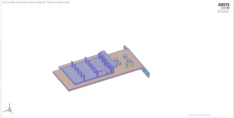
* Start by importing the given model and open the space modul to edit the model.
* The given model is ready with the all geomentry and also with enclosers. So we can do only the share tropology which is used to carry the information from nodes of one model to other models. It will coincides the nodes of one model to other model.
space claim -----> workbench -----> share tropology
* After completing the geomentry open the mesh modul to mesh the model.
* Generate the mesh to the given model and insert the sizing option to the fins, graphics card, PCB board, so that results will be more aqurate. In body sizing we wants to enable the capture curve as yes which will refine the curve surface.
* To generate the mesh with proper refined mesh size, we have to undergo gride indipendent study.
so, consider three case of mesh size,
--->Case 1 : general mesh size = 10m, sizing = 1m
--->Case 2 : general mesh size = 5m, sizing = 0.8m
--->Case 3 : general mesh size = 0.3m, sizing = 0.7m
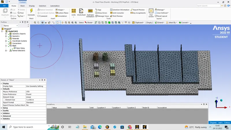
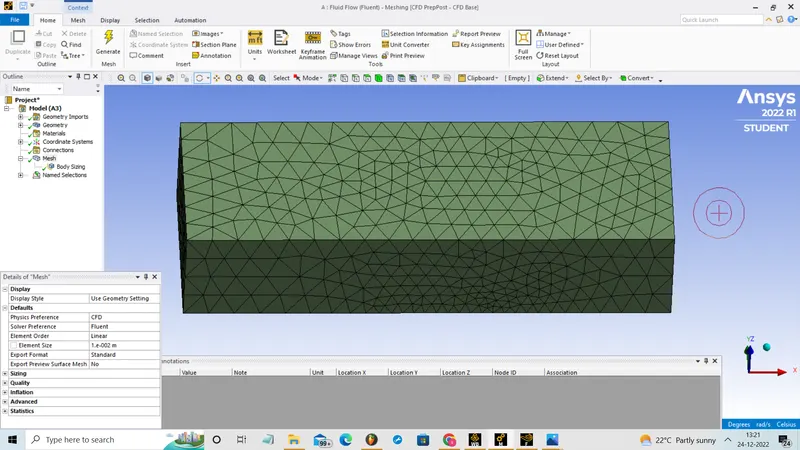
* Consider the fine mesh size with considerable element numbers by comparing the three case of study.
mesh -----> generative mesh -----> element size
mesh -----> insert -----> body sizing or method -----> elemnt size -----> capture curve (yes)
* After the mesh open the set up modul and here we have to set the condition like physics, boundery conditions, type of analysics, Solution setups and the requried outups.
* Here enable the steady state solver because we considering only the final results or condition not considering the changes in every time (sec). Pressure based is used because the velocity of air low ( less than 0.3 of mach number ) .
* Enable the energy because we wants maximum temperature and heat transfer coefficient which is the part of energy transfer.
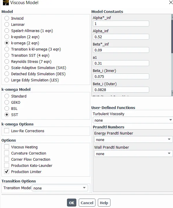
* Select the default K-omega ,SST turbulent model which is much useful to capture the change near the body.
* For the material selection some of the materials are assumed based on the reseach papers. To create materials go to material database and choose the material. if the material is not available select any material and change the properties of its.
MATERIAL ASSUMED :
| PARTS | MATERIALS | THERMAL CONDUCTIVITY (W/m.K ) | SPECIFIC HEAT CAPACITY (J/kg.K) | DENSITY (Kg/m^3) |
| Fin | Aluminium | 202.4 | 871 | 2719 |
| Processor or graphic card | Silicon | 153 | 703 | 2330 |
| PCB | Polystyrene | 0.027 | 1210 | 55 |
| Heat transfer fluid | air | 0.0242 | 1006.43 | 1.225 |
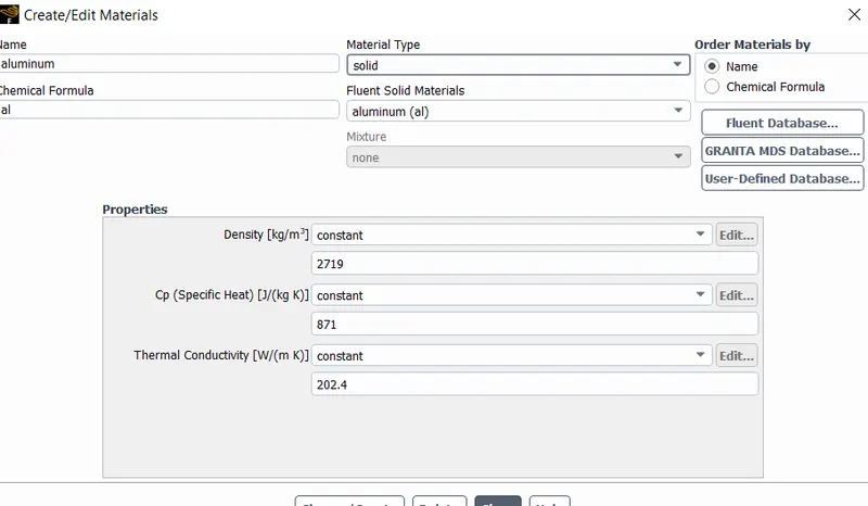
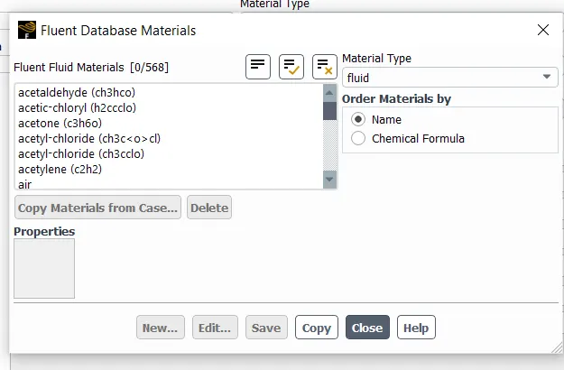
* Assign the created material to the respective parts in the cell zone option and when assigning for graphics card we wants to give the sorce term as 1 and constant and give heat generated is 15625000 W/mm^3 by assuming the heat decipated as 1W.
HEAT GENERATED,
Qg = Heat decipated / Volume of graphic card
= 1W / 64m^3
= 1W / 64*10^(-9) mm^3
= 15625000 W/mm^3
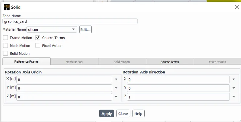
* Assign the boundary conditions for the inlet, outlets . For the inlet , velocity inlet and consider as three cases of velocity and temperature is default 300K and for the outlet is default pressure outlet.
The case of velocity inlet,
---->Case 1: Velocity = 1m/s
---->Case 2: Velocity = 3m/s
---->Case 3: Velocity = 5m/s
* Then set the solution report by using the definition. The three report is need for these challenge Maximum Temperature, Average Temperature, Heat Transfer Coefficient.
Average Temperature,
Definition ----> new ----> solution report ----> Area weighted average----> choose the temperatureand and graphics card surface exposed to air and enable print to console.
Average Temperature,
Definition ----> new ----> solution report ----> Facet max ----> choose the temperatureand and graphics card surface exposed to air and enable print to console.
Heat Transfer Coefficient,
Definition ----> new ----> solution report ----> Area weighted average ----> choose the wall flux and surface heat transfer coefficient and graphics card surface exposed to air and enable print to console.
* Select the initialize option to initialize it.
* Give 300 iteration and if the solution is not converged and then increase the iteration and calculate it.
* Create the contours for Temperature, heat transfer coefficient and velocity in the created plane.
* In the result option we can create the plots for Temperature and velocity which is used to compare the results.
* Do these procedures to all the three case of velocity by dublicating it.
RESULT :
MESH INDIPENDENT STUDY :
Keeping the velocity v=1m/s as constant and changed the mesh size and body sizing as three cases.
| CASES | MESH SIZE | BODY SIZING | NO OF ELEMENTS | MAXIMUM TEMPERATURE | HEAT TRANSFER COEFFICIENT |
| 1 | 0.01 m | 0.001 m | 196820 | 333.09789 | -4.5951497 |
| 2 | 0.005 m | 0.0008 m | 326958 | 332.96777 | -4.5326295 |
| 3 | 0.003 m | 0.0007 | 423695 | 332.35801 | -4.4541514 |
From the above table we can observe that when the mesh is refined the results becomes more accutrate and we use the case 3 mesh size for further simulations for other velocities.
SIMULATED RESULTS BY VARYING THE VELOCITY :
CASE 1 :
Inlet Velocity = 1m/s
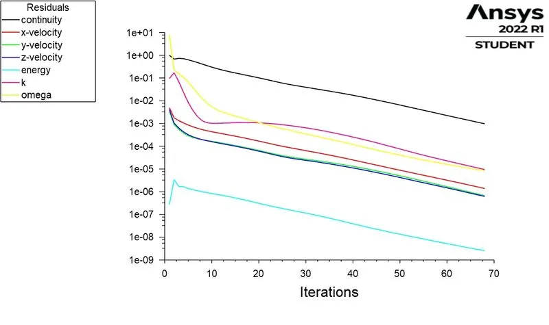
RESIDUAL POLTS :
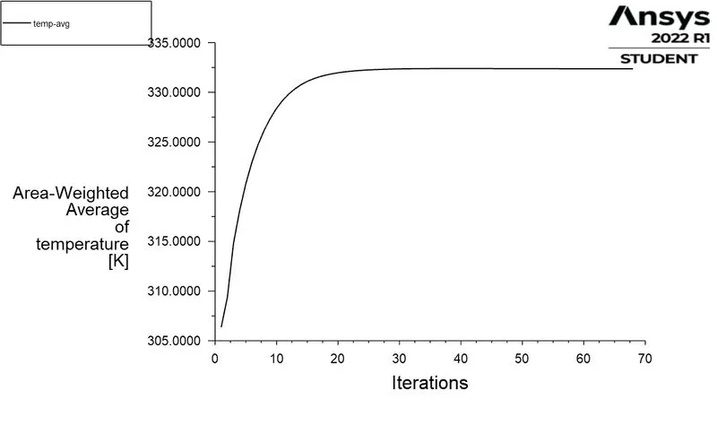
AVERAGE TEMPERATURE POLTS :
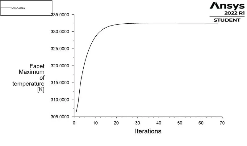
MAXIMUM TEMPERATURE POLTS :
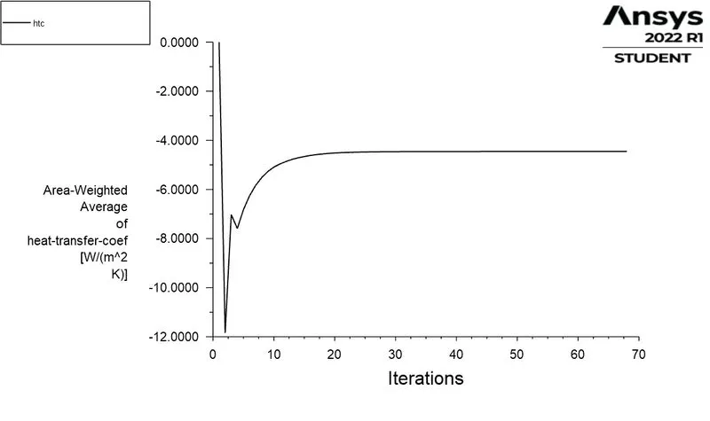
HEAT TRANSFER COEFFICIENT :
TEMPERATURE CONTOUR :
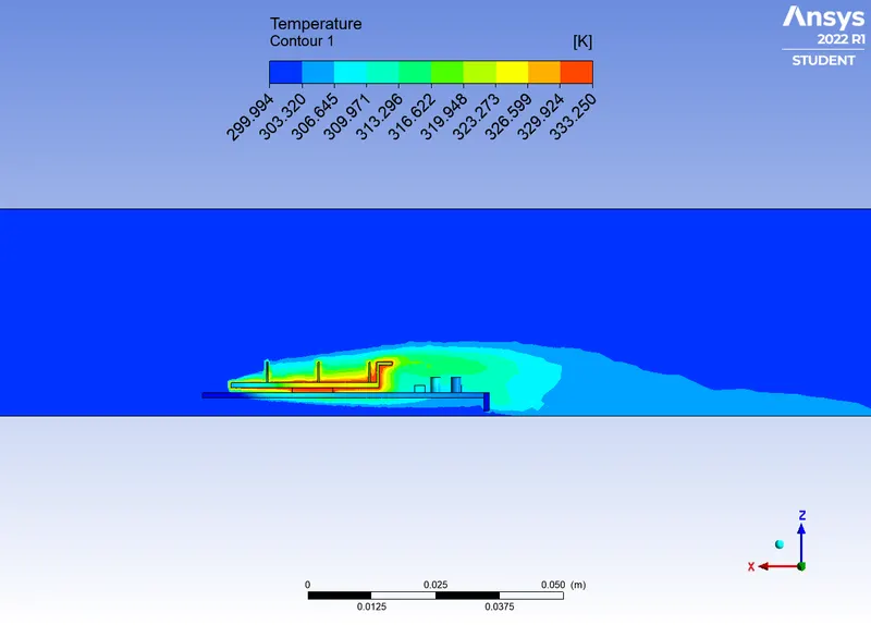
from the temperature contor we can observe that temperature is more at the graphics card and the edges of the fins when compare to the other parts. The heat transfer coefficient is about -4.45 which denotes that the heat transfer coefficient is less at low velocity and maximum temperature less.
VELOCITY CONTOUR :
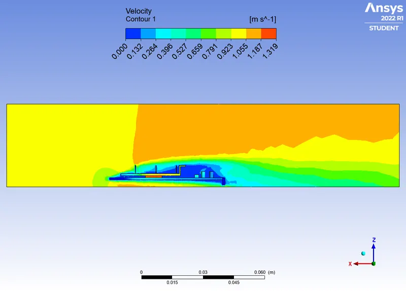
STREAMLINE :
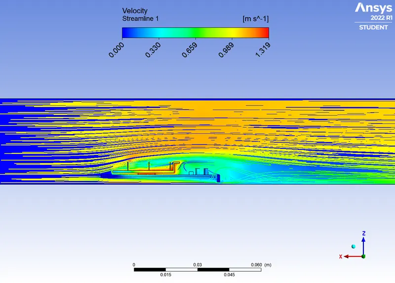
The streamline plot shows the flow separation occurs at the fins and some of the edes are formed behinde the fins.
CASE 2 :
Inlet Velocity = 3m/s
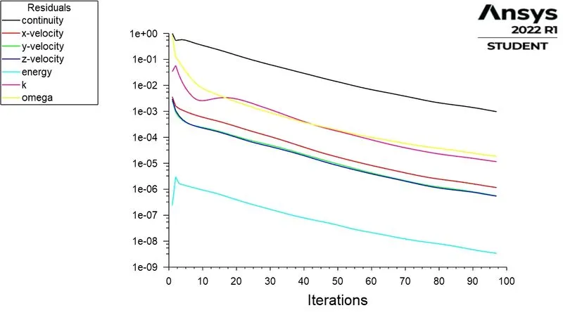
RESIDUAL POLTS :
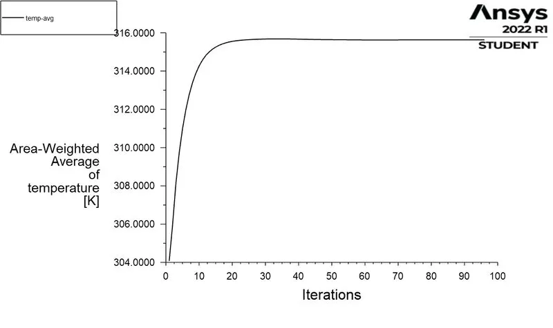
AVERAGE TEMPERATURE POLTS :
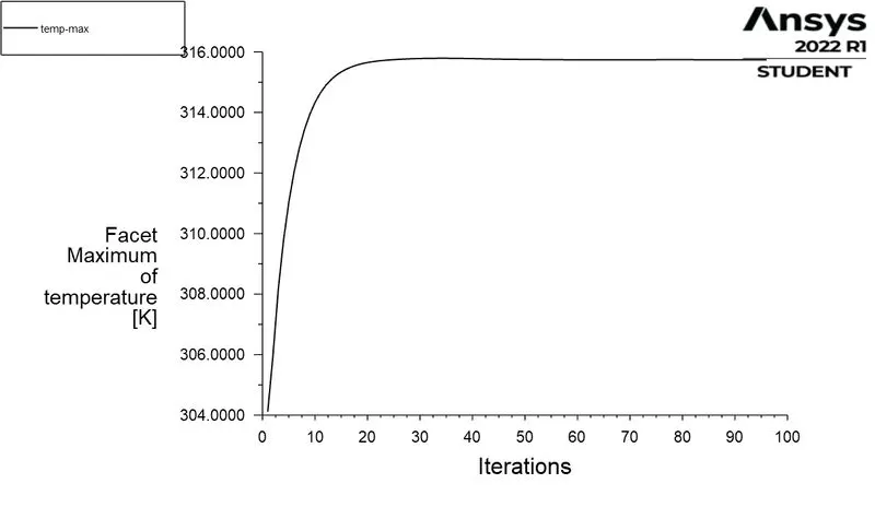
MAXIMUM TEMPERATURE POLTS :
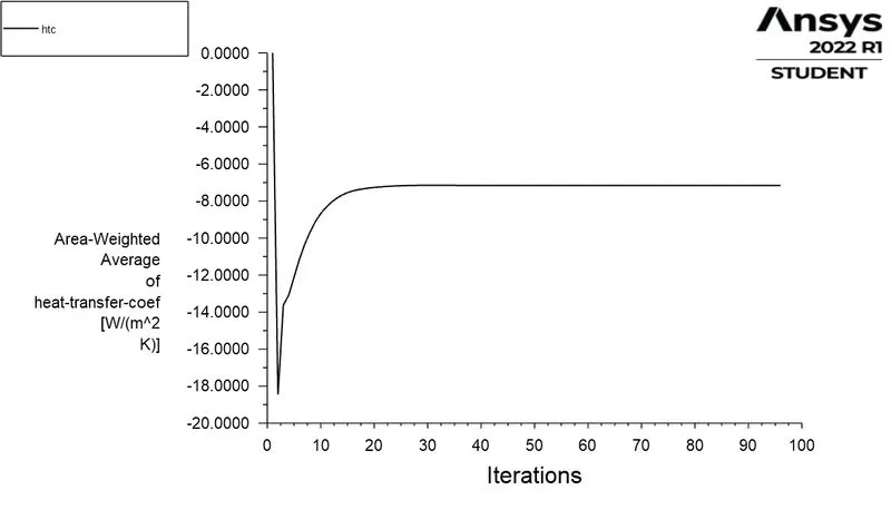
HEAT TRANSFER COEFFICIENT :
TEMPERATURE CONTOUR :
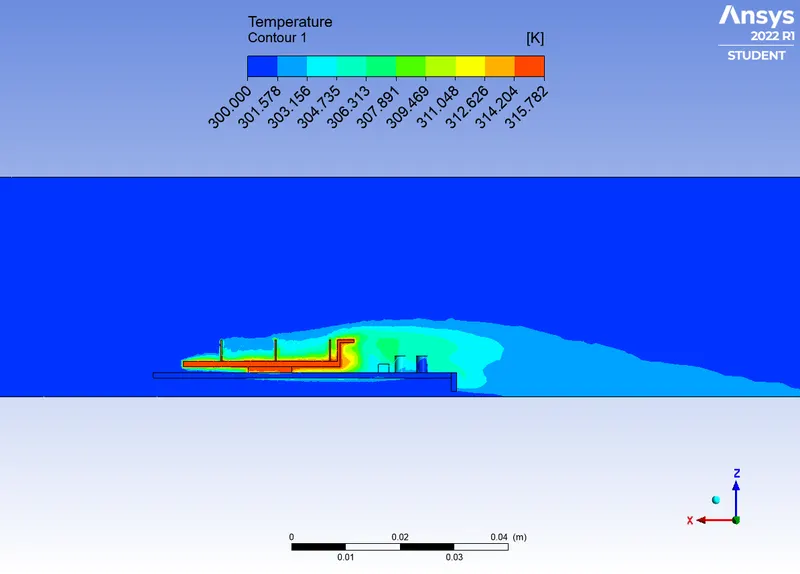
from the temperature contor we can observe that temperature is more at the graphics card and the edges of the fins when compare to the other parts. The heat transfer coefficient is about -7.1637 which denotes that the heat transfer coefficient is increases when inlet velocity increases and maximum temperature decreases.
VELOCITY CONTOUR :
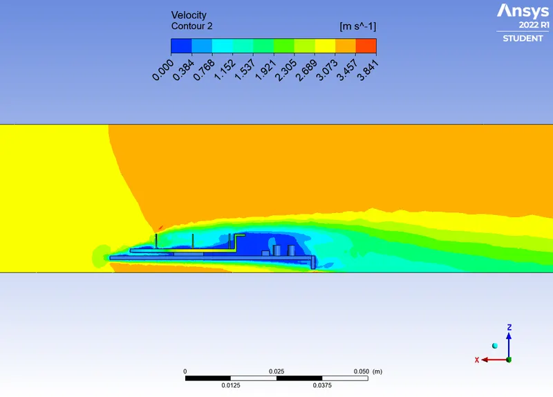
STREAMLINE :
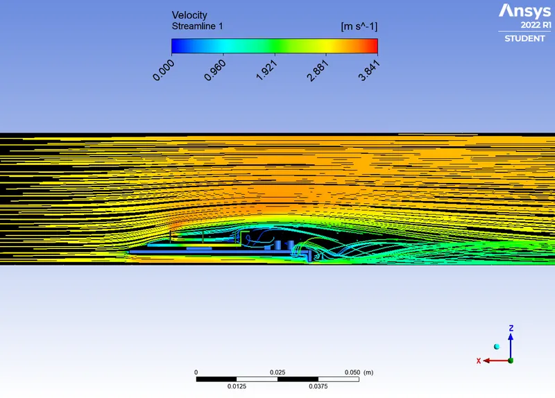
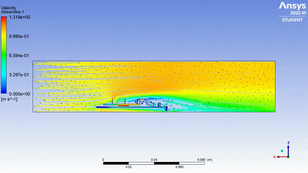
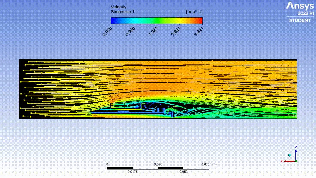
As the velocity increased the flow separation also increased at the fins parts and the formation f flow vectors are more when compare to the velocity 1m/s.
CASE 3 :
Inlet Velocity = 5m/s
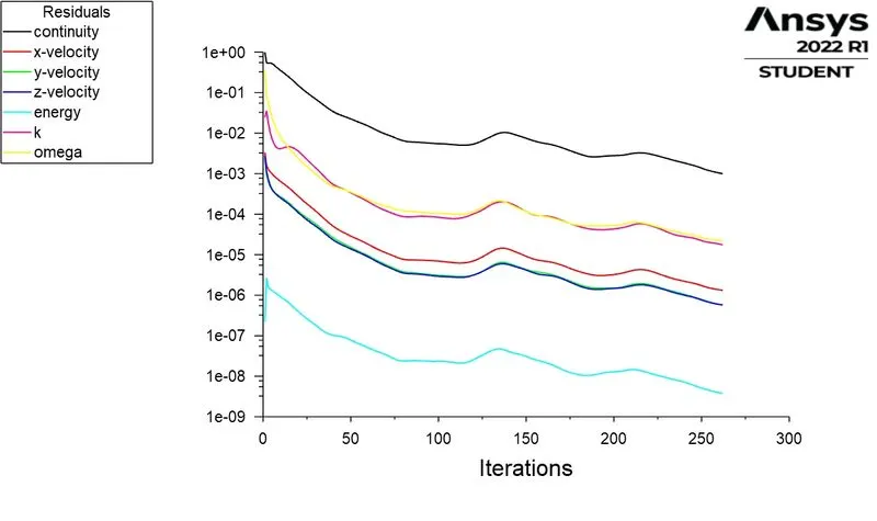
RESIDUAL POLTS :
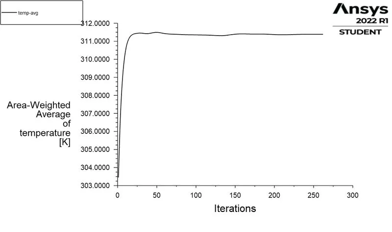
AVERAGE TEMPERATURE POLTS :
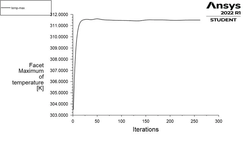
MAXIMUM TEMPERATURE POLTS :
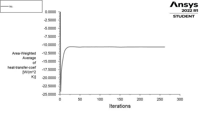
HEAT TRANSFER COEFFICIENT :
TEMPERATURE CONTOUR :
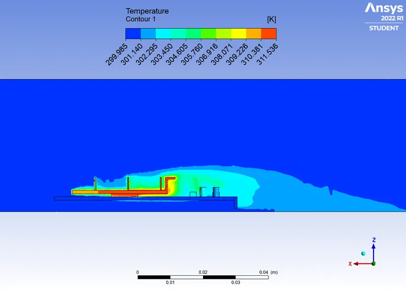
from the temperature contor we can observe that temperature is more at the graphics card and the edges of the fins when compare to the other parts. The heat transfer coefficient is about -10.652 which denotes that the heat transfer coefficient is increases when inlet velocity increases and maximum temperature decreases.
VELOCITY CONTOUR :
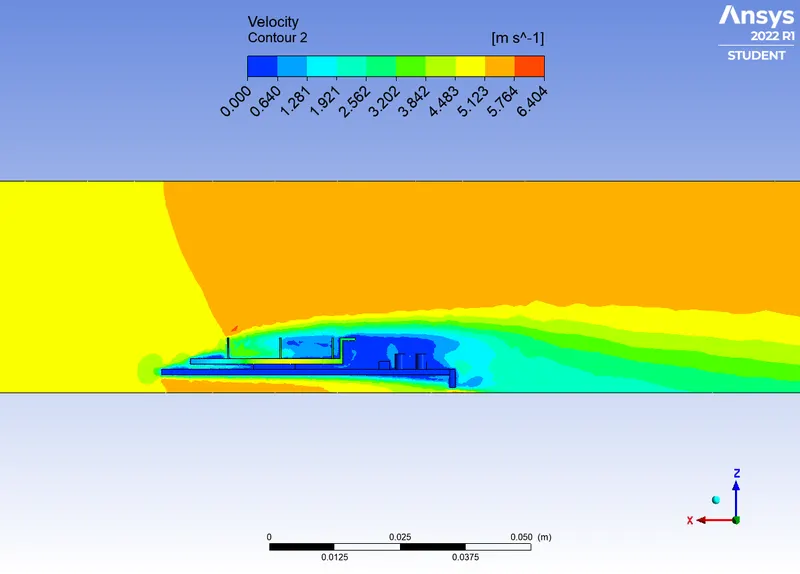
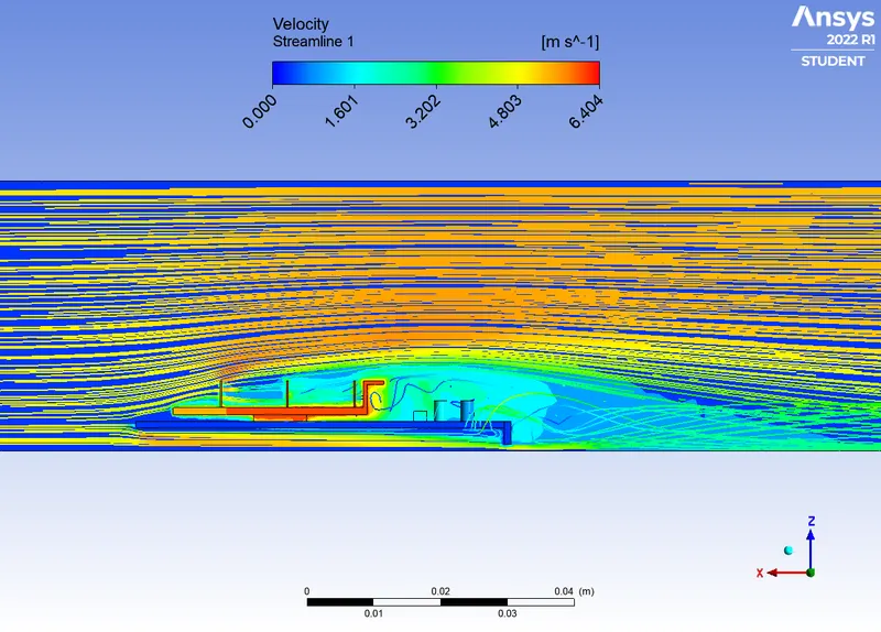
As the velocity increased the flow separation also increased at the fins parts and the formation f flow vectors are more when compare to the velocity 1m/s.
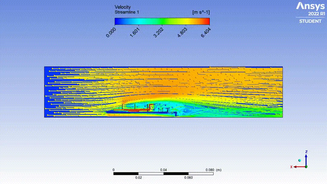
TABLE :
| CASE | VELOCITY | AVERAGE TEMPERATURE | MAXIMUM TEMPERATURE | HEAT TRANSFER COEFFICIENT |
| 1 | V = 1 m/s | 332.48367 | 332.35801 | -4.4541514 |
| 2 | V = 3 m/s | 315.62856 | 315.744002 | -7.1637422 |
| 3 | V = 5 m/s | 311.38286 | 311.49265 | -10.652401 |
EXPLANATION :
From the table we can observe that the maxmimum temperature decreases and the heat transfer coefficient increases when the velocity increases. These is because when the velocity of inlet air increases the heat flux increases as heat transfer coefficient is depends on the heat flux with respect to change in temperature. So the heat transfer coefficient increases . As the heat transfer coefficient increases the temperature decreases due to the convection of heat to the surrounding air. The fins is used to increase the convection of heat because the heat convection increases when the surface area increased. since the fin as large surface area it increases the convections. So, it also helps the heat transfer to occurs at faster rate.
HOTSPOTS :
From the temperature distribution, we can see hotspots in the fin and base near the surface that is in contact with the processor. Based on the thermal conductivity of the material this temperature is distributed accordingly amongst the component. We see a few high-temperature zones on fin away from processor depicting their high susceptibility to heat due to their geometry.
CONCLUSIONS :
* As the size of mesh is becomes fine the number of elements increases and the results of temperature distribution odtained is more accurate.
* From the above table it is observed that, the temperature of componenets of graphics card decreases with increase in inlet velocity.
* Hence it can be conclued that a higher inlet velocity results in better cooling and decreases the average temperature thus keeping the components safe from damage.
* It can be observed that the temperature of components increases as the inlet velocity decreases from 5 m/s to 1m/s, also proving that higher velocity results in better cooling.