Week 6 - CHT Analysis on a Graphics card
Aim
Perform a steady-state conjugate heat transfer analysis on a model of a graphics card
Introduction
A CHT (Conjugate Heat Transfer) analysis is useful where there are multiple modes of heat transfer in our computational domain, like conduction and convection. Having such a great number of applications for this type of simulation makes it important to be studied in depth.
Solving & Modelling approach
- Run the simulation by varying the velocity from 1m/sec to 5m/sec for at least 3 velocities and discuss the results.
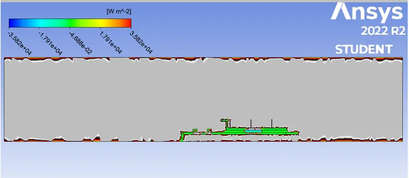
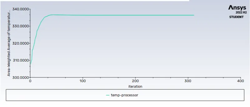
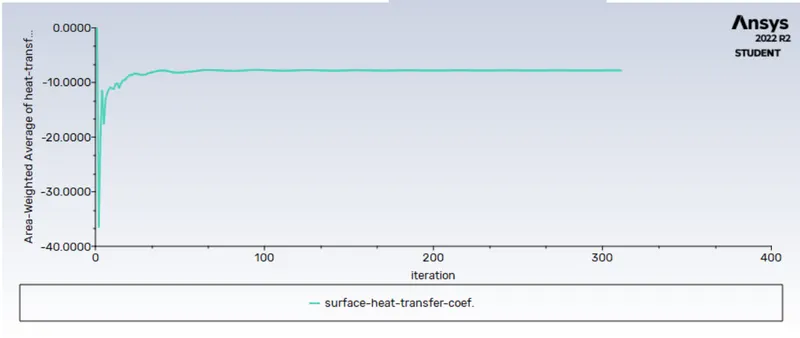
- Find out the maximum temperature and heat transfer coefficient attained by the processor.
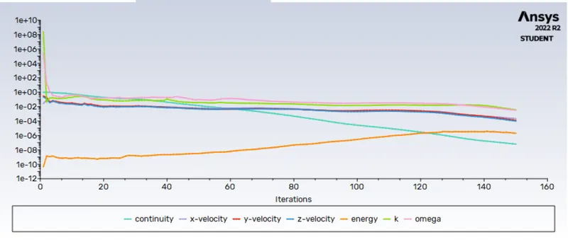
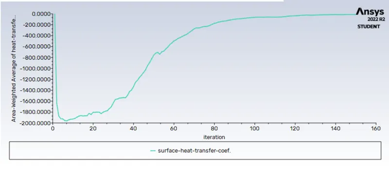
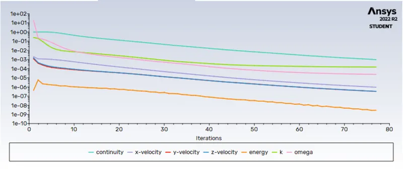
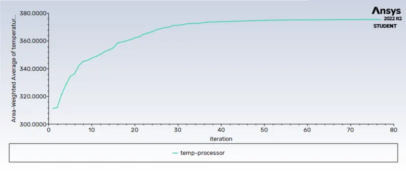
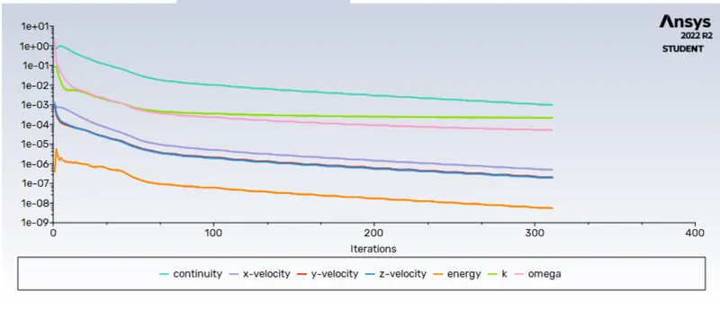
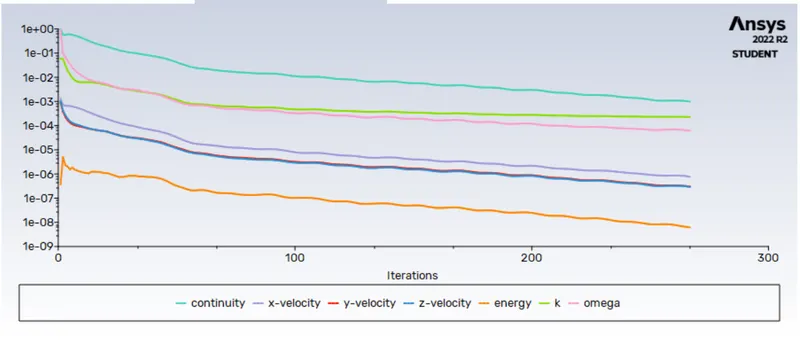
- Prove that the simulation has achieved convergence with appropriate images and plots.
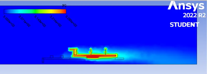
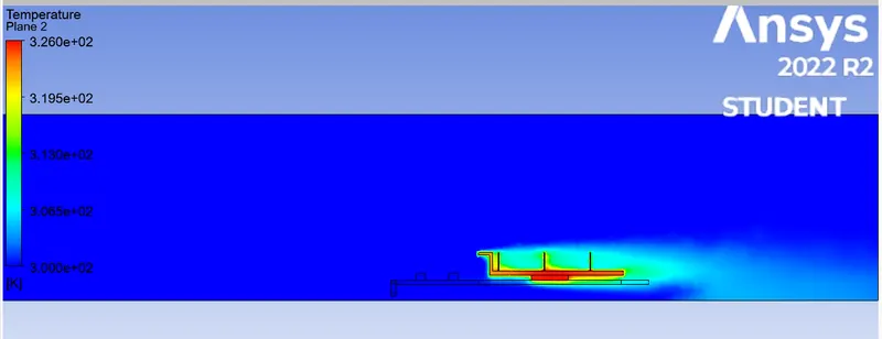
- Identify potential hotspots on the model.
Pre-processing and solver setting
geometry
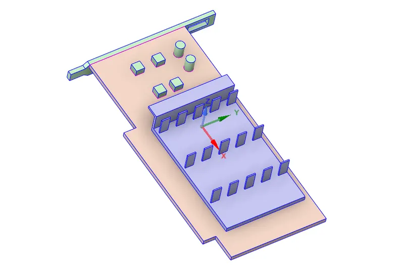
enclosure is created over the geometry in spaceclaim
Mesh ( BASE MESH)
1) Target length 10mm for the enclosure
2) Traget lenght for the graphics card 2mm

NAME SELECTION
1)INLET = velocity inlet perform @ different velocity = ( 1 m/s , 3m/s , 5m/s)
2) OUTLET = pressure outlet
3)DOMAIN = wall
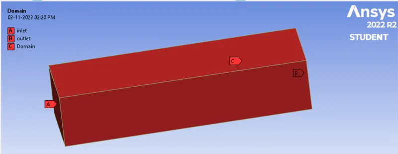
4) FIN
5) PROCESSOR
6) PCB

SETUP&SOLUTION
solver
Type : pressure based
Veloctiy formulation : Absolute
Time : steady state
viscous model : K-omega SST
Materials & their properties:
1) Fins --> Aluminium
Standard aluminium is available in Fluent database.
Density = 2719 Kg/m^3
Heat capacity = 871 J/KgK
Thermal conductivity = 202.4 W/mK
2) Processer --> Silicon
Since the silicon is not available in Fluent's solid database, I had to define it
Density = 2330 Kg/m^3
Heat capacity = 703 J/KgK
Thermal conductivity = 153 W/mK
3) PCB --> pcb (glass-reinforced epoxy laminate material)
Since the FR4 is not available in Fluent's solid database, I had to define it
Density = 55 Kg/m^3
Heat capacity = 1210 J/KgK
Thermal conductivity = 0.27 W/mK
4) Fluid --> Air
Standard air is available in Fluent database.
Density = 1.225 Kg/m^3
Heat capacity = 1006.43 J/KgK
Thermal conductivity = 0.0242 W/mK
Viscosity = 1.7894e-05 Kg/m-s
Cell zone condition
1 Fin - solid - Aluminium
2 processor - solid - silicon
3 Base - solid -PCB
4 Enclosure - fluid - air
BOUNDARY CONDITION
1) INLET - velocity inlet = perform @ different velocity = ( 1 m/s , 3m/s , 5m/s)
2) OUTLET = pressure outlet
Residuals
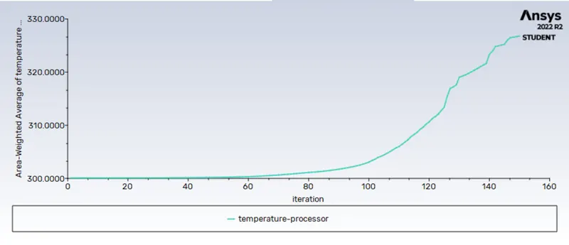
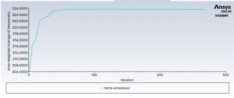
temperature of the processor
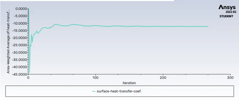
surface heat transfer coeffiecient
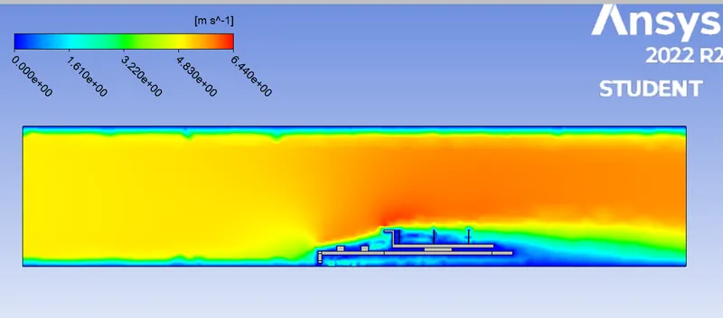
contour plots
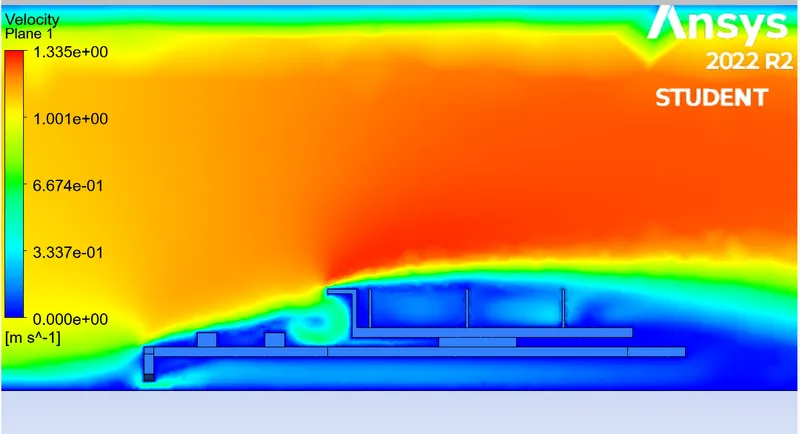
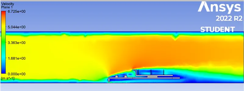
velocity
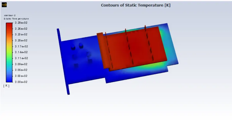
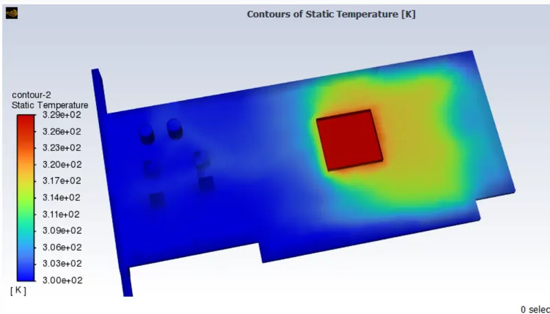
temperature
surface heat transfer
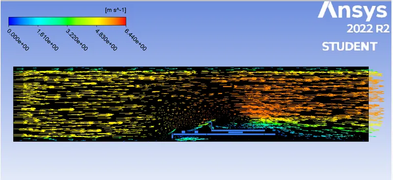
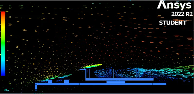
velocity vector
HOTSPOT IN FIN
HOTSPOT IN PROCESSOR
result for base
| 5 | 325 | -12.568 w/ m^2 K |
case -2
Target length of the enclosure = 5 mm
Taget length of the gaphics card = 0.4 mm
1) velocity = 1 m/s
residual polt
temperature of the processor
surface heat transfer coeffiecient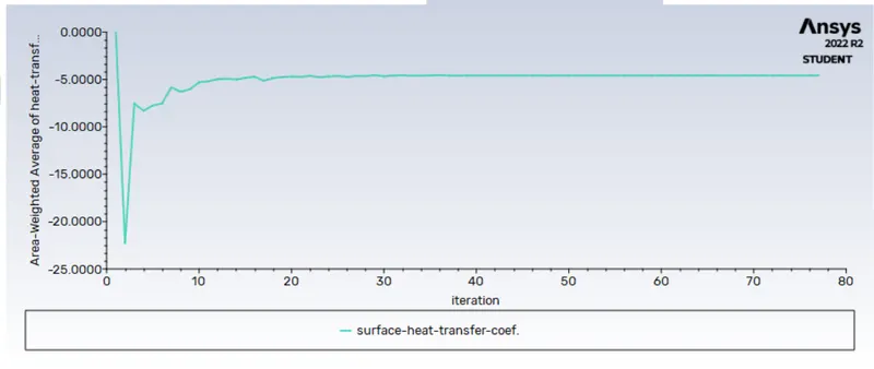
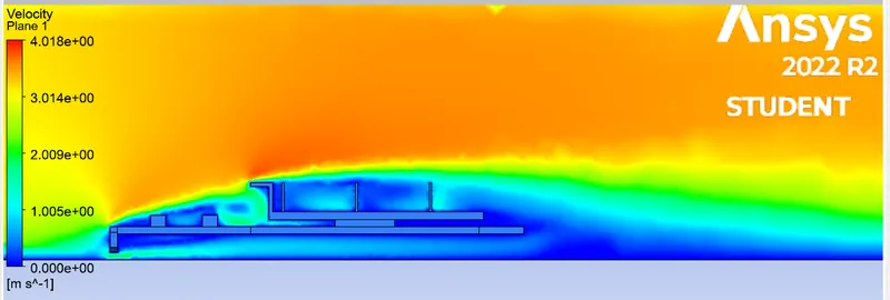
velocity contour
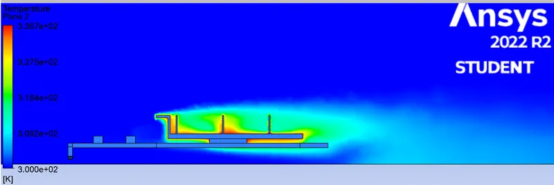
temperature contour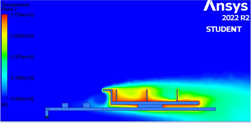
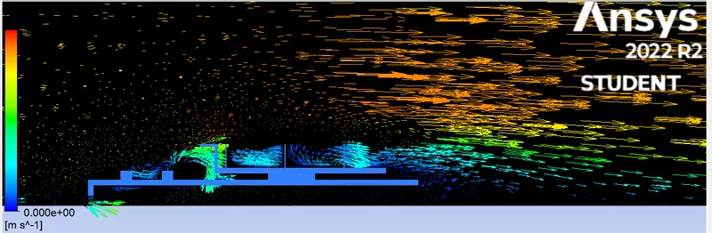
velocity vector
1) velocity = 3 m/s
residual polt
temperature of the processor
surface heat transfer coeffiecient
velocity contour
temperature contour
velocity vector
1) velocity = 5 m/s
residual polt
temperature of the processor
surface heat transfer coeffiecient
velocity contour
temperature contour
velocity vector

Results
| velocity | temperature of processor | surface heat tansfer coefficient |
| 1 | 375 | -4.568 w/ m^2 K |
| 3 | 336 | -7.800 w/ m^2 K |
| 5 | 325 | -12.806 w/ m^2 K |
CONCLUSION
- As the number of elements increases the accurate results of temperature distribution is obtained
- From the above table, it is fairly notable that, the net temperature of components of graphics cards decreases with an increase in inlet velocity.
- Hence it can be inferred that a higher inlet velocity results in better cooling and lower the average temperature thus keeping the components safe from damage.
- Furthermore, it can be observed that the temperature of components increases as the inlet velocity decreases from 5 m/s to 1m/s, also proving that higher velocity results in better cooling.