Week 6 - CHT Analysis on a Graphics card
Aim:
- To perform a steady-state CHT analysis on G=graphics card
- Selecting appropriate materials for each component.
- Simulate with varying velocity from 1m/s to 5m/s for three velocity.
- To find out potential hotspots in the graphics card.
- To carry out a mesh independent study.
Procedure:
- The geometry file was imported onto space claim
- The file was meshed initially with baseline mesh and further conducted a refinement to carry out the mesh independent study.
- Now, in fluent the meshed file is given with solid and fluid condition for the components and appropriate materials were assigned to each component.
- Now the graphics card is simulated for varying inlet velocity from1m/s to 5 m/s (3 cases)
Pre-processing:
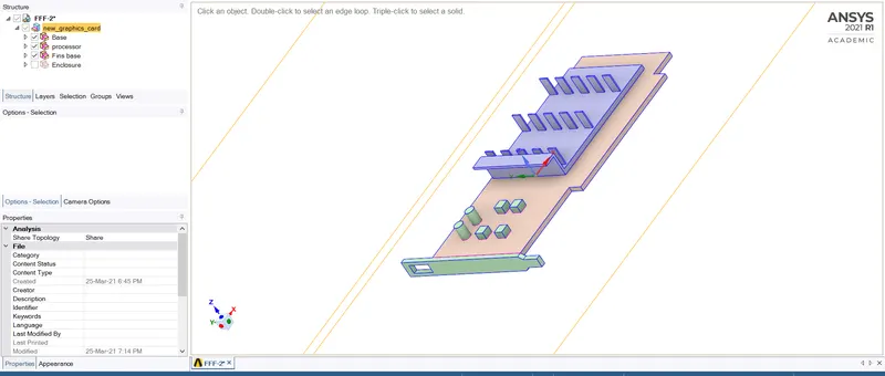
- Geometry was imported into the space claim now the share topology features are enabled.
Meshing:
- The file was initially meshed with base line mesh and further refined and the final refined mesh file was simulated for varying inlet velocity
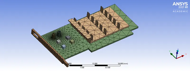
Mesh file 1
The body was meshed with default mesh.
No. of elements:70912
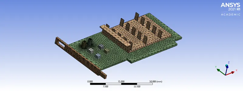
Mesh file 2
A body sizing was given to the enclosure with an element size of 5mm.
No. of elements:161987
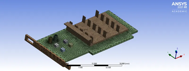
Mesh file 3
The previously meshed file was further given a body sizing combined with a Hexa-dominant mesh on the fins to completely capture the conduction through the fin.
No. of elements:509787
Fluent setup:
The fluent was setup initially with all the general parameters
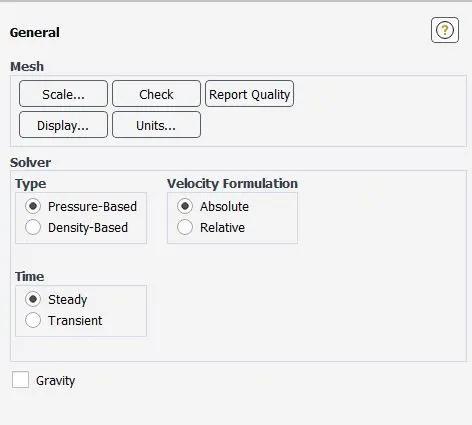
The energy was turned on since it requires the calculation of temperature.

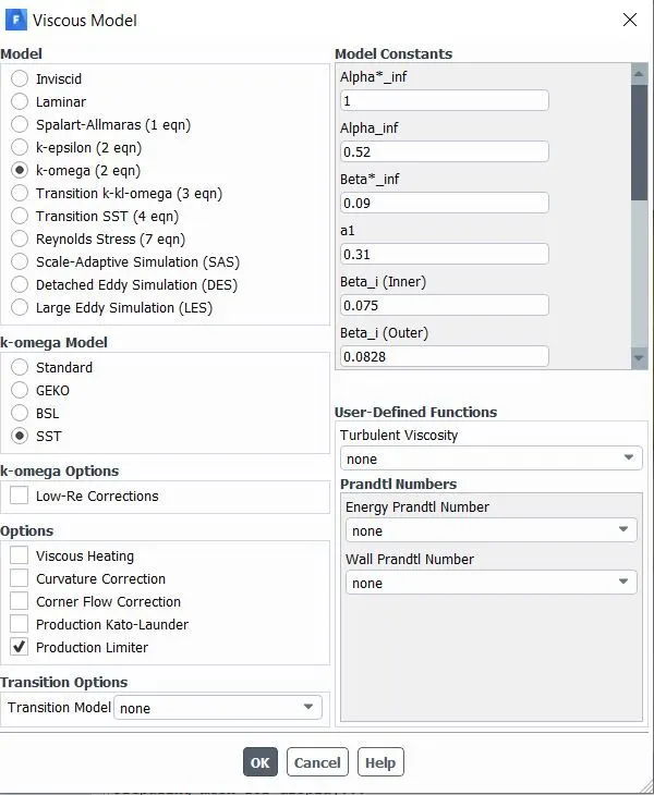
Viscous model was selected appropriatly:
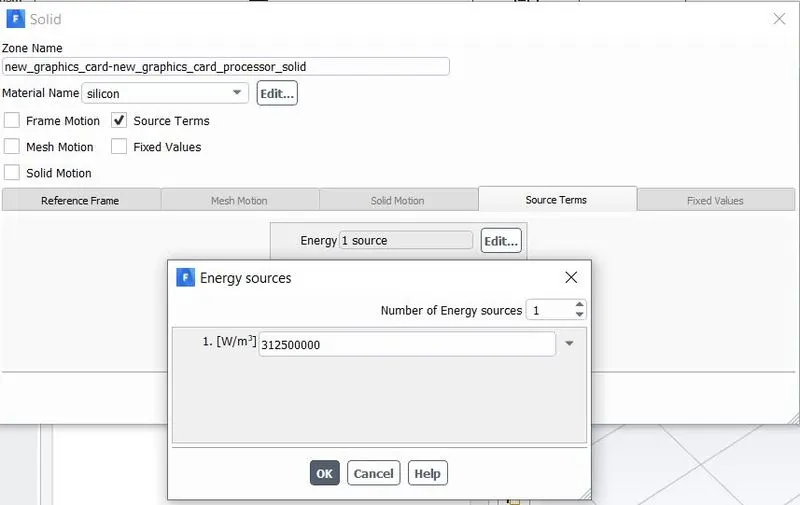
In the cell zone condition fluids and solid components were assigned and the processor was considered to be giving an output of 20W heat which computed a heat generation of
`(20W)/(64*10^9m^3) = 312500000W/m^3`
Materials Assigned:
| Sl/No. | Componenet | Material assigned |
| 1 | Processor | Silicon |
| 2 | PCB | Mica |
| 3 | Fin | Copper |
Results:
Post-processing:
Refined mesh condition
Inlet veocity: 1m/s
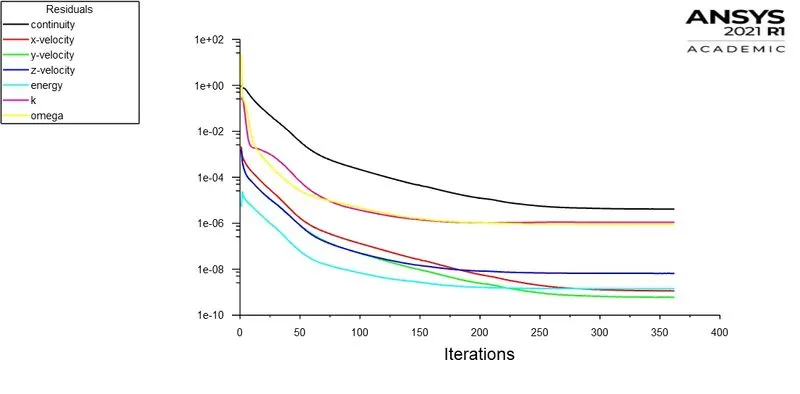
Residuals:
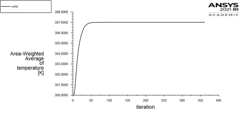
Avg Outlet temp:
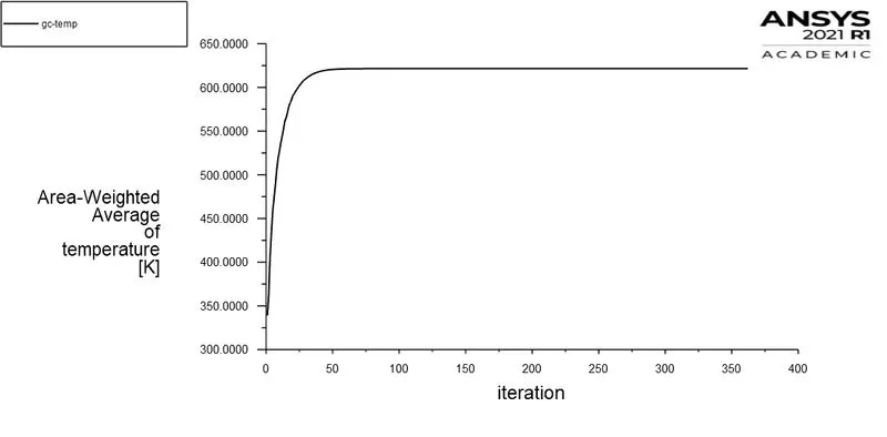
Avg Processsor temp:
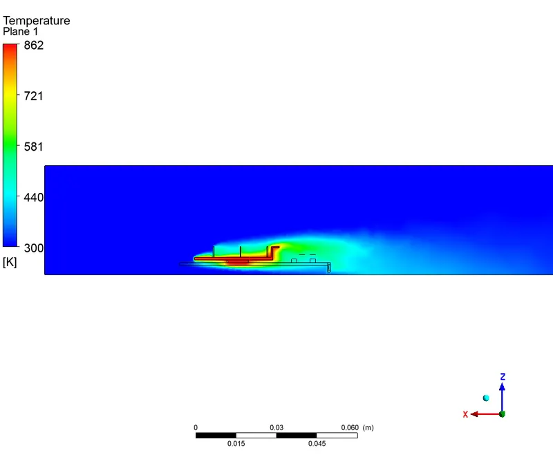
Temp contour:
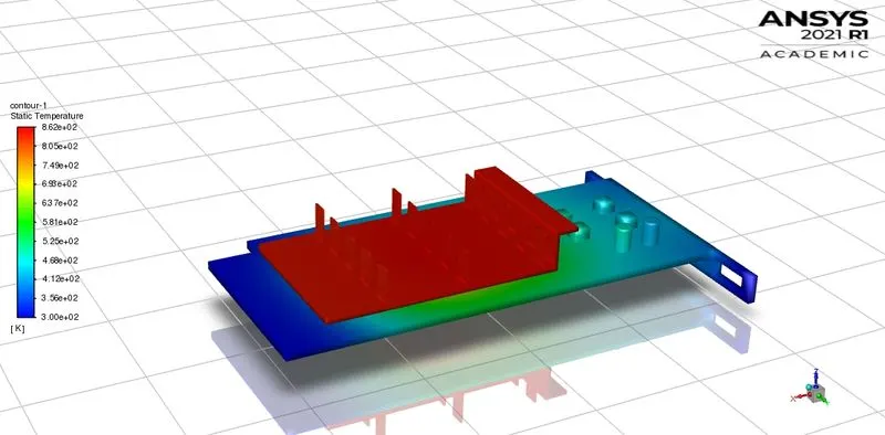
Surface temperature contour:
Velocity Contour:
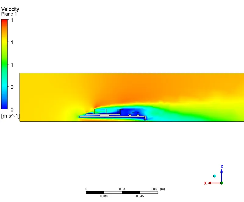
Inlet veocity: 3m/s
Residuals:
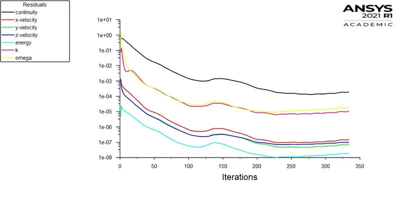
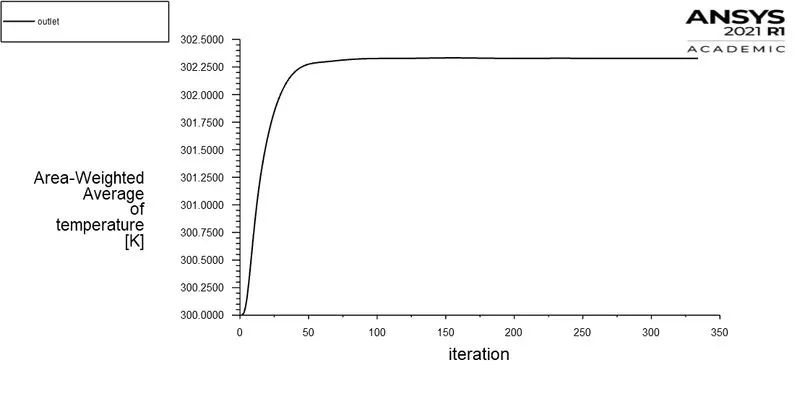
Avg Outlet temp:
Avg Processsor temp:
Temp contour: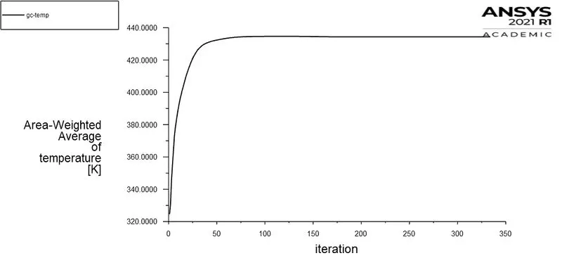
Velocity Contour:
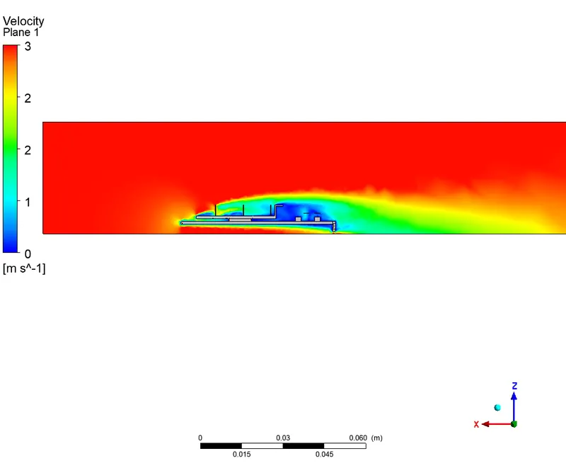
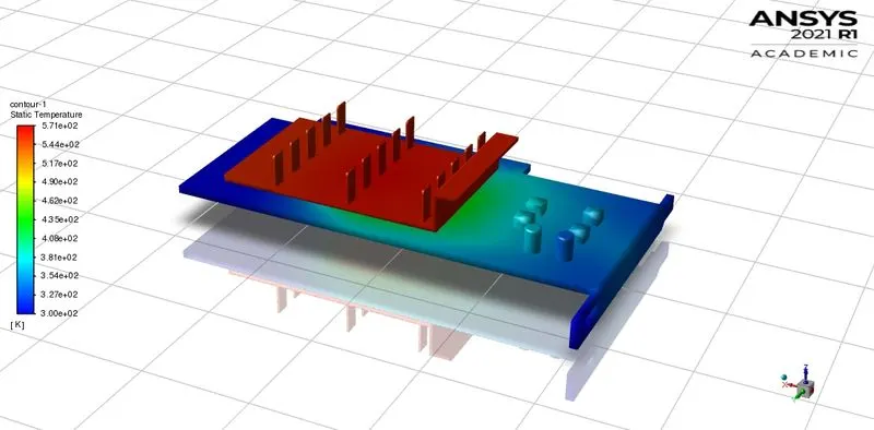
Surface temperature contour:
Inlet veocity: 5m/s
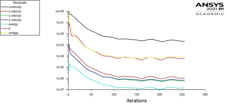
Residuals:
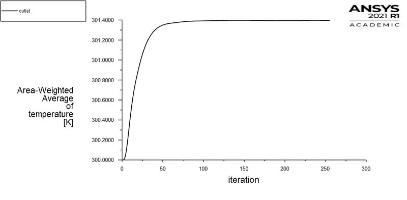
Avg Outlet temp:
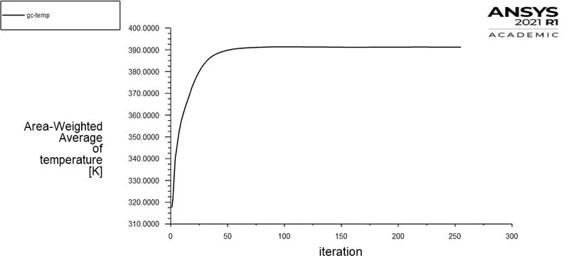
Avg Processsor temp:
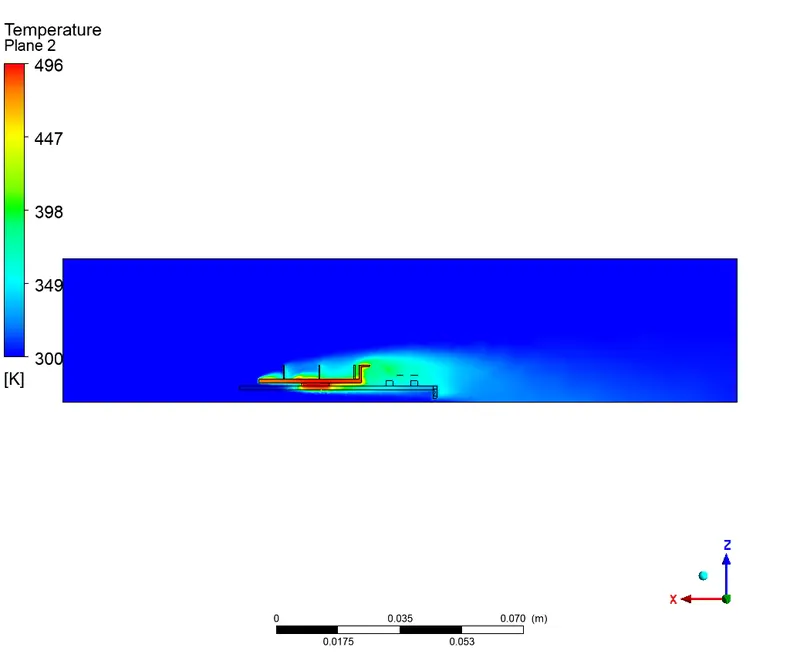
Temp contour:
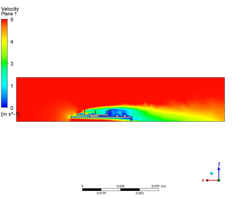
Velocity Contour:
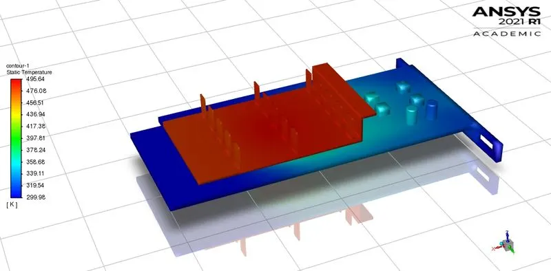
Surface contour:
Comparison of velocity with temperature:
| Sl/No | Inlet Velocity(m/s) | Avg outlet temperature(K) | Avg Processor temperature (K) | Avg surface heat transfer coeff on processor (W/m^2-K) |
| 1 | 1 | 307 | 621.5 | 48.94 |
| 2 | 3 | 302.3 | 434.3 | 83.81 |
| 3 | 5 | 301 | 391 | 108.11 |
Mesh independent study:
| Sl/No | Inlet Velocity(m/s) | Avg outlet temperature(K) | Avg Processor temperature (K) | Avg surface heat transfer coeff on processor (W/m^2-K) |
| 1(baseline) | 1 | 306.88 | 606.79 | 45.72 |
| 2 | 1 | 308.03 | 593.53 | 52.51 |
| 3 | 1 | 307 | 621.5 | 48.94 |
- Further mesh independent study could not be carried out due to limitation of no. of elements in the student version.
Potential hotspots:
Most of the heat are dissipated through the fin which helps to conserve the PCB from causing any heat damage. thus copper is best selected for fin as copper is a good conductor of heat and hence, it is distributing the heat properly to the overall surface area and providing a better heat dissipation effect with a higher heat transfer rate.
Also the PCB material was selcted as mica which has a llow conductivity thus does not conduct the heat from the processor.
Conclusions:
Refining mesh gives the best results thus the main heat dissipation being through the fins we refine the mesh at that region.
Increasing velocity increases the convection as there occurs and increase in the Reynolds number. thus increasing the velocity of the fluid carries away most of the heat in the fins which cause the reason for decreasing surfce temperature and the avg outlet temperature with increasing velocity.
Mesh/ grid dependency test is very important to get confidence over results.