Week 6 - CHT Analysis on a Graphics card
Aim: To perform state-state heat transfer analysis on a graphics card (GPU)
Theory:
The Graphic card is responsible for rendering an image to your monitor, and it does this by converting data into a signal your monitor can understand. The better your Graphic card the better and smoother an image can be produced.
in graphic card heat is generated in the processor because processor run electricity so when the currrent is flowing through the processor, it has some resistance so due to this heat is generated. to reduce the temperature of processor, fins are attached to processor so it can work efficiently and increase its life span. the material used for maling processor are copper, silica. fins are most commonly used in heat exchanging devices and the material used for making of fins are aluminium. the base on which processor,power connectors are placed and the base is made up of steel. so here we are going to simulate on the conjugate geat transfer analysis on the graphic card
Conjugate Heat Transfer Analysis
Computational Fluid Dynamics (CFD) and more specifically conjugate heat transfer (CHT) analysis can accurately predict heat transfer by simultaneously solving all the relevant solid and flow field heat transfer processes, for example, conduction through solids, free and forced convection in the gases/fluids and thermal radiation.
The CHT approach has an advantage over FE thermal analyses in that wall heat transfer coefficients and their local variations on surfaces are directly calculated within the model rather than based on simplified empirical calculations. The CHT approach, therefore, has benefits for those applications where heat transfer is either non-uniform or difficult to calculate empirically.
The heat transfer projects have covered a wide range of aerodynamic and hydrodynamic industrial applications but projects typically had objectives such as:
- Temperature distribution analysis.
- Heat flux rate analysis – calculation of wall heat flux rates or heat transfer coefficients.
- Visualization of heat transfer features for improved understanding of system flow phenomena.
- Identification of localized ‘hot spots’ or heat sinks in checking against specified requirements.
- Evaluating variation in temperature peaks for different operating conditions/ failure modes.
- Assessing insulation or heat shield effectiveness and optimizing material selections.
- Coupling CHT with FE analysis to evaluate thermally induced stresses, expansion, or fatigue.
- Temperature field analysis
- CFD thermal analysis
- Heat transfer coefficient analysis
- Heat transfer rate analysis
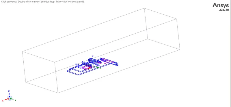
step no-1:- importing the geometry to spaceclaim
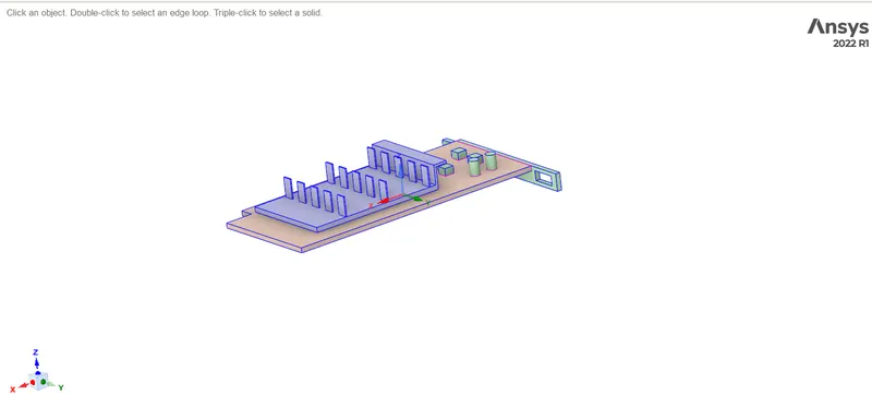
graphics card
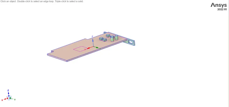
base
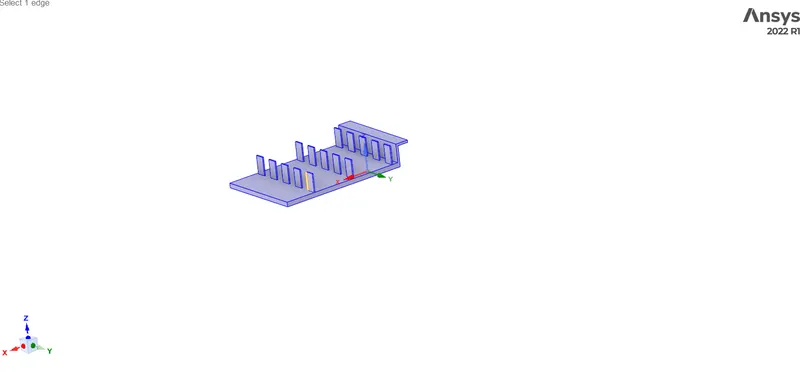
fins
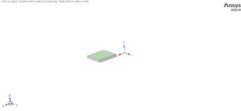
processor
enclosure
we have enclosed the graphics card by enclosure
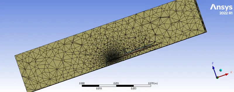
step2 meshing the geometry
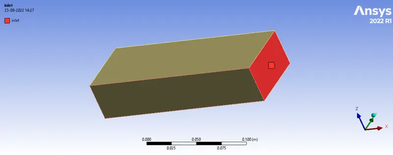
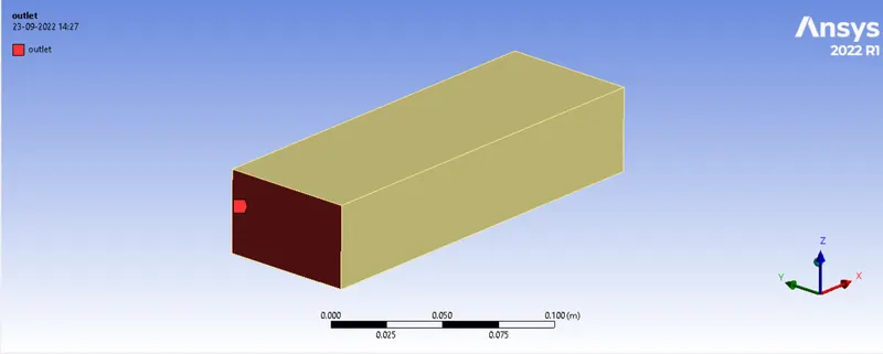
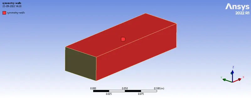
named selection done to the geometry
inlet
outlet
step 3 :-setting up the physics
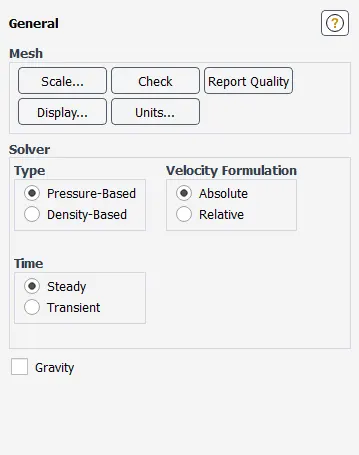
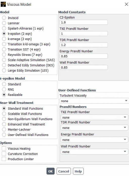
general
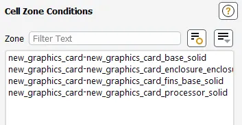
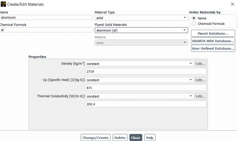
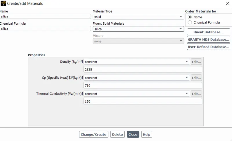
materials selection for different parts of grahpics card
base :- steel
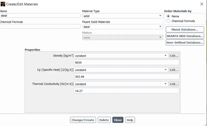
fins :-
processor
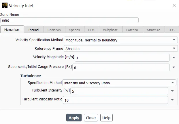
air inlet conditions
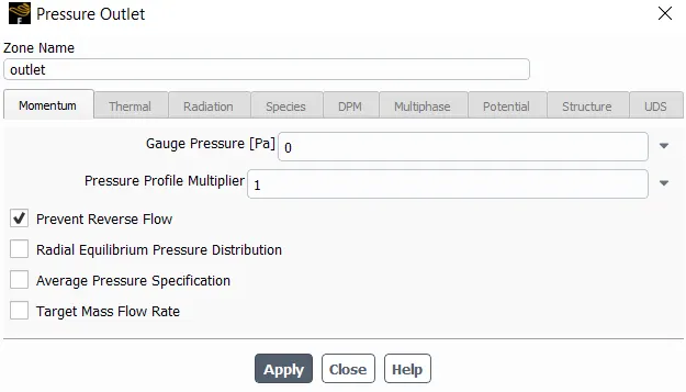
outlet conditions
hybird intilization done
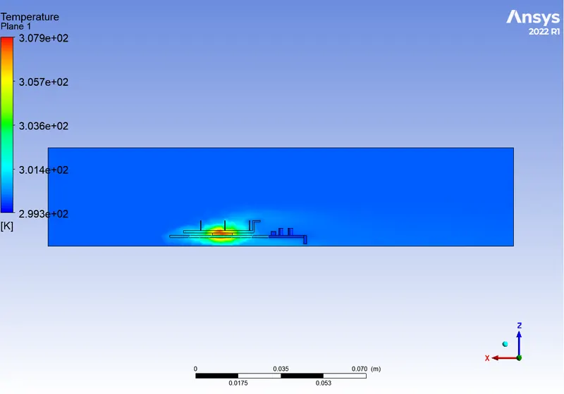
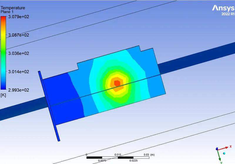
results :- case 1 results
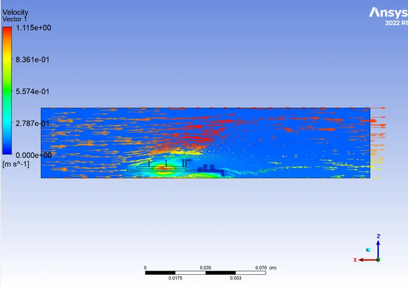
for the inlet 1m/s
velocity vectors
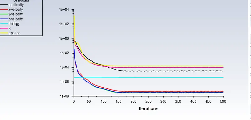
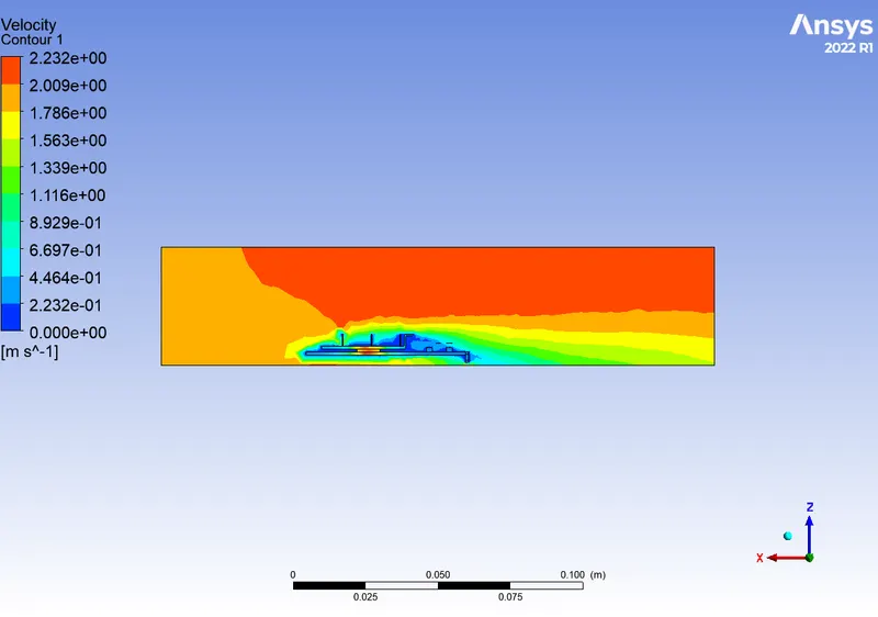
case 2 :- for the velocity of 2m/s
results
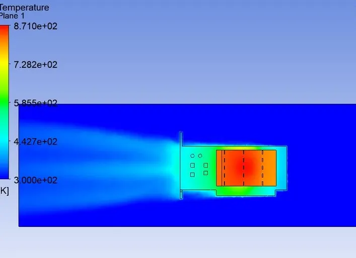
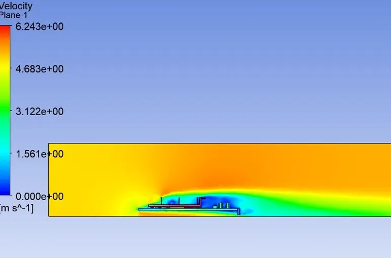
case 3 : for the velocity 5m/s
temperature contour
velocity countor
conclustion :-
from the above results we can concluid that as the inlet velocity of the inlet air increses the graphics card processor temperature decreses.