Week 6 - CHT Analysis on a Graphics card
OBJECTIVE: Perform a steady-state conjugate heat transfer analysis on a graphics card setup.
THEORY:
The term conjugate heat transfer (CHT) is used to describe processes which involve variations of temperature within solids and fluids, due to thermal interaction between the solids and fluids. The exchange of thermal energy between the two physical bodies is called study of Heat Transfer, the rate of transferred heat is directly proportional to the temperature difference between the bodies. A typical example is the heating or cooling of a solid object by the flow of air in which it is immersed and some other example includes conduction through solids, free and forced convection in the gases/fluids and thermal radiation.Typical applications of this analysis type exist as, but are not limited to, the simulation of heat exchangers, cooling of electronic equipment, and general-purpose cooling and heating systems.
Conjugate heat transfer corresponds with the combination of heat transfer in solids and heat transfer in fluids. In solids, conduction often dominates whereas in fluids, convection usually dominates. Efficiently combining heat transfer in fluids and solids is the key to designing effective coolers, heaters, or heat exchangers. Forced convection is the most common way to achieve high heat transfer rate. In some applications, the performances are further improved by combining convection with phase change (for example liquid water to vapor phase change).
Heat transfer in solids and heat transfer in fluids are combined in the majority of applications. This is because fluids flow around solids or between solid walls, and because solids are usually immersed in a fluid.
Modes of heat transfer
- Conduction: diffusion of heat due to temperature gradients. A measure of the amount of conduction for a given gradient is the heat conductivity.
- Convection: when heat is carried away by moving fluid. The flow can either be caused by external influences, forced convection; or by buoyancy forces, natural convection. Convective heat transfer is tightly coupled to the fluid flow solution.
- Radiation: transfer of energy by electromagnetic waves between surfaces with different temperatures, separated by a medium that is at least partially transparent to the (infrared) radiation. Radiation is especially important at high temperatures, e.g. during combustion processes, but can also have a measurable effect at room temperatures.
An accurate description of heat transfer modes, material properties, flow regimes, and geometrical configurations enables the analysis of temperature fields and heat transfer.
Typical design problems involve the determination of:
- Overall heat transfer coefficient, e.g. for a car radiator.
- Highest (or lowest) temperature in a system, e.g. in a gas turbine, chemical reaction vessels, food ovens.
- Temperature distribution (related to thermal stress), e.g. in the walls of a spacecraft.
- Temperature response in time dependent heating/cooling problems, e.g. engine cooling, or how fast does a car heat up in the sun and how is it affected by the shape of the windshield?
The fluid flow and heat transfer problems can be tightly coupled through the convection term in the energy equation and when physical properties are temperature dependent. While analytical solutions exist for some simple problems, we must rely on computational methods to solve most industrially relevant applications.
CHT can be performed to improve cooling performance of the water jacket and increase engine life. Advancements in cooling for applications such as gas turbines components require improved understanding of the complex heat transfer mechanisms and the interactions between those mechanisms, which our engineers can perform without hassle. Critical cooling applications often rely on multiple thermal protection techniques, including internal cooling, external film cooling, etc. which are efficiently used by our analysis to cool components and limit the use of coolant. We do extensive support for Motor and Battery CHT Analysis to get optimized design for High voltage systems. Conjugate Heat Transfer analysis provides the temperature distribution in solid and coolant of the engine and clear insight on velocity distribution and mechanism of heat transfer of coolant. Results of CHT analysis become input to structural simulations as thermal loads.
We have a wide experience in Engine CHT Analysis for various type of engines like Bikes, Passenger Cars, Racing cars, Commercial Vehicles, Marine, Agricultural equipment and Earth-moving equipment etc.
Mathematical Modeling
The flow of thermal energy from matter occupying one region in space to matter occupying a different region in space is known as heat transfer. Heat transfer can occur by three main methods:
- Conduction
- Convection
- Radiation
Physical models involving conduction and/or convection only are the simplest while buoyancy-driven flow or natural convection and radiation models are more complex. Depending on your problem, ANSYS Fluent will solve a variation of the energy equation that takes into account the heat transfer methods you have specified.
- Modeling Conductive and Convective Heat Transfer
ANSYS Fluent allows you to include heat transfer within the fluid and/or solid regions in your model. Problems ranging from thermal mixing within a fluid to conduction in composite solids can therefore be handled by ANSYS Fluent. When your ANSYS Fluent model includes heat transfer you will need to activate the relevant physical models, supply thermal boundary conditions, and input material properties that govern heat transfer and/or vary with temperature as part of the setup.
`( ∂ ( ρ E )) / ∂ t + ∇ . ( v ( ρ E + p ) ) = ∇ . ( k e f f ∇ T - ∑ h j J j + ( τ e f f . v ) ) + s h`
SIMULATION PROCEDURE:
- The geometry is loaded into Spaceclaim.
- The graphics card consists of a processor, PCB base, aluminum fin base, memory cards, and capacitors.
- CHT analysis requires both the solid and the liquid volume under consideration, Spaceclaim gives an option of volume extract for selecting edges for fluid volume, here the solid volume under consideration is graphics card components and the liquid volume under consideration is air.
- The general principle underlying the fact that the heat generated by the processor is carried away by air. The aluminum fin is used for increasing the surface area of heat transfer.
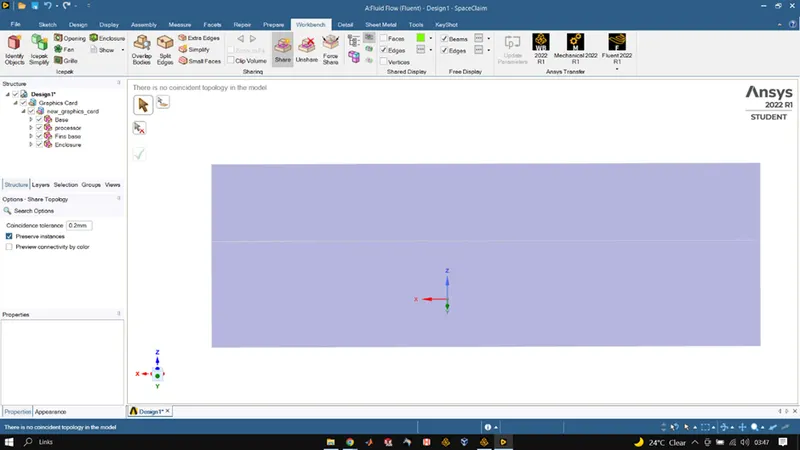
- The share topology is set to reduce the interpolation error and to make the mesh conformal.
- It is then loaded into the meshing window for creating the named selection, and setting the baseline mesh and refined mesh.
- The fluid material and the solid material are separated and the construction of the material is selected for the same.
- The necessary contour images and graphs are studied to understand the behavior of temperature, velocity, and surface heat transfer coefficient at the interface.
GEOMETRY PREPARATION
We initialized space-claim and imported the CAD file for graphics card model which then enclosed in a fluid volume using the enclosure tool. Then we used the share topology tool in the workbench section so that all the shared surfaces share their topology so that while meshing we get a conformal mesh. We also used the section view and checked for interference so that we don’t get any issue during meshing.
BASE OF GRAPHICS CARD
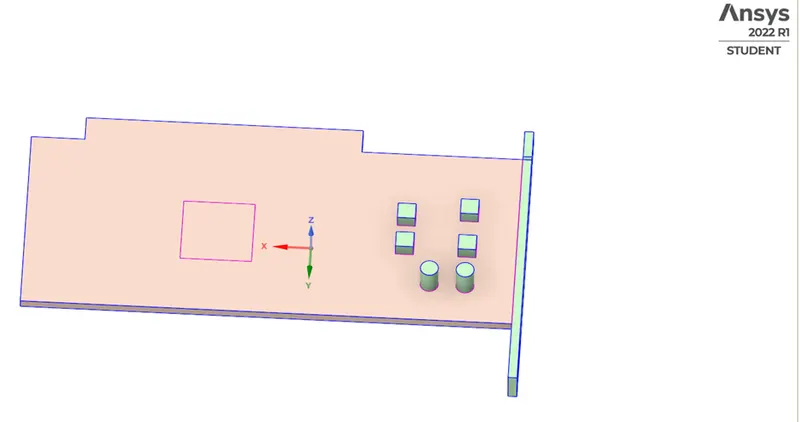
PROCESSOR OF GRAPHICS CARD
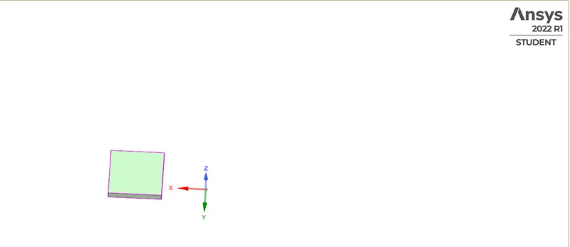
COOLING FINS OF GRAPHICS CARD
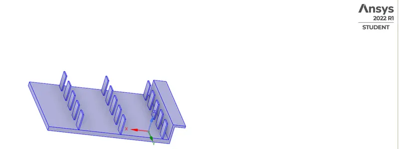
GRAPHICS CARD MODEL
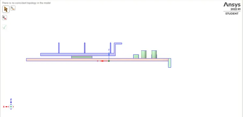
MODEL INSIDE HE FLOW VOLUME ENCLOSURE
MESHING
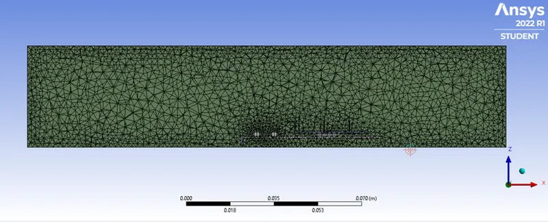
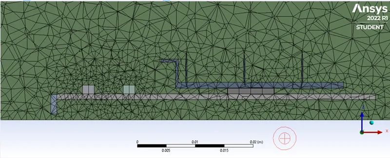
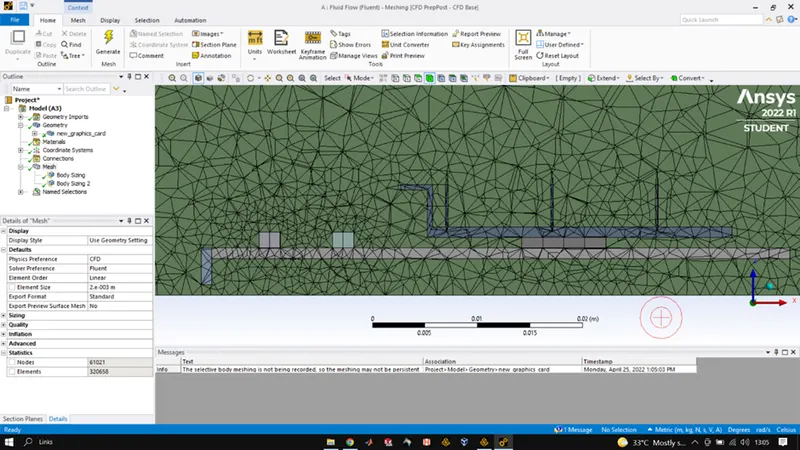
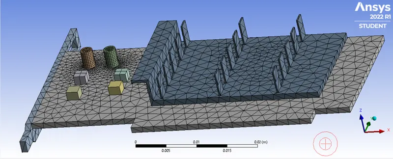
After completing all the steps in Space-claim we head towards Mesh GUI and there we first use the face selection tool to name our boundaries as inlet outlet and symmetry after that individual major component was named for the graphics card. Once all the naming was done, we created a base mesh using the generate mesh option, after analysis of base mesh we reduced the element size for the base mesh to 0.002m so as to make the mesh finer. Once that was done, we inserted sizing option for the cooling fins and processor as these are the two areas in the whole model which needs more refitment coz they will be having the highest temperature interactions among them and having a refined mesh for them would result in more accurate results of simulation. The element sizing for fin was 0.001m and for the processor was 0.0001m after generating the final mesh we had around 370k elements which is fine enough as per the limitations of academic license. Otherwise, we could have made the mesh more refined by allowing maximum size also to 0.002m for the enclosure area and some more refinement for fins and processor as well.
FLUENT/SETUP
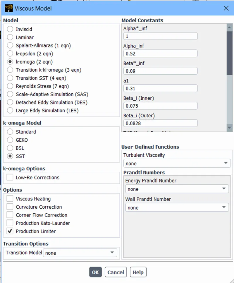
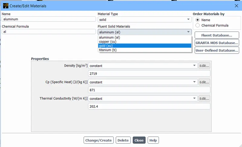
Once the mesh was refined, we closed the mesh GUI and opened our Ansys fluent setup where we initially performed a mesh check once it was ok we went to general physics where we selected Steady time method for simulation and we checked in the energy equation calculations also as we were dealing with temperature changes, for the viscous model we went with K-omega SST model as it gives accurate results in finely resolved heat profiles. After that we added titanium, aluminum and gold. We used titanium for the base of the graphics card, gold for the processor and aluminum for the fins. After adding the materials, we checked all the zones and made sure solids have solid and fluid have fluid zones and also made the processor as the source of heat with value of around 9e7. After that we defined the inlet boundary condition and use the velocities as 5m/s 3m/s and 1m/s for 3 different cases to observe the change in simulation results. After that we used the definition tool to plot various area weighted average properties such as temperature of processor, temperature of fin and standard deviation of temperature. After that the simulation was initialized using standard solver and upon initialization, we added contour of temperature on the graphics card model to see the temperature distribution upon completion of simulation. Convergence criteria for the residuals were unchanged and simulation was run for 500 iterations. Though we reached convergence at a lesser iteration for all the 3 cases.
Once the calculations were done we used the maximum tool in volume report of definitions to calculate maximum value of temperature and HTC for the processor.
RESULTS:
FOR V = 5m/s
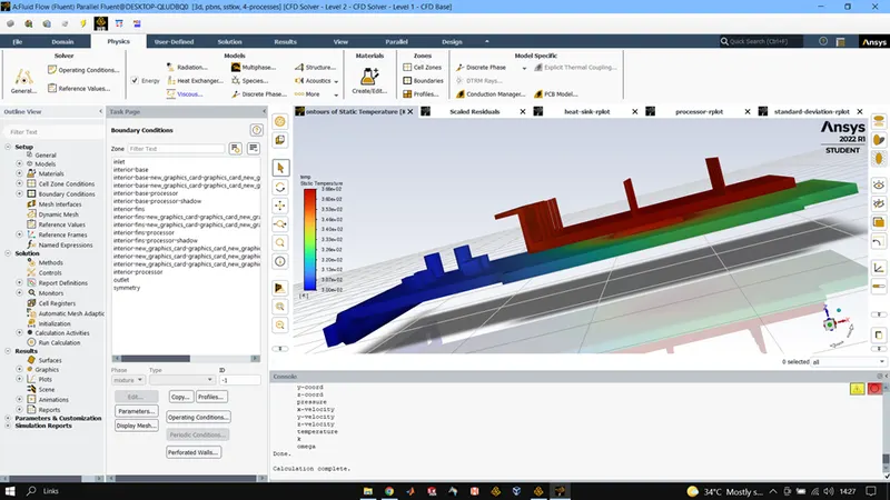
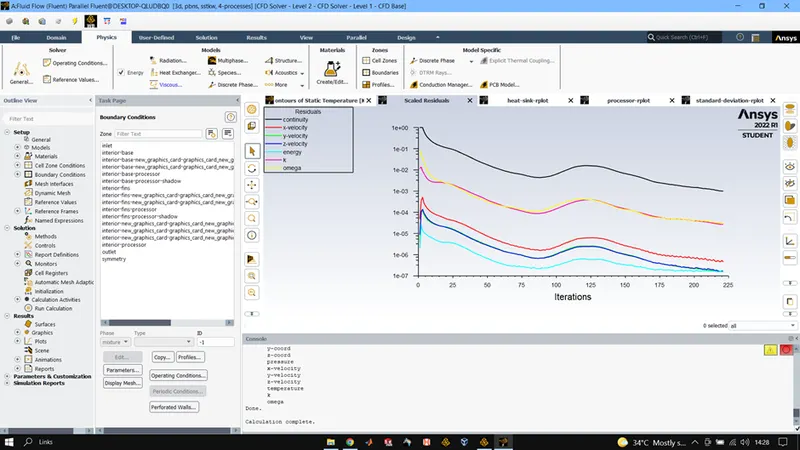
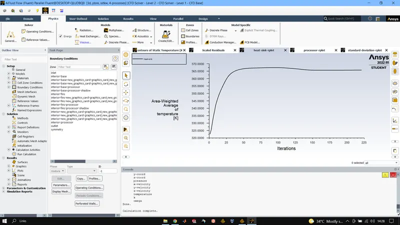
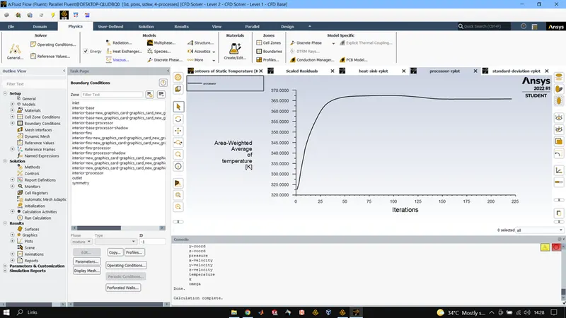
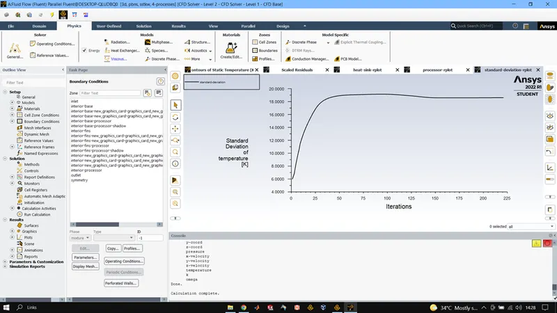
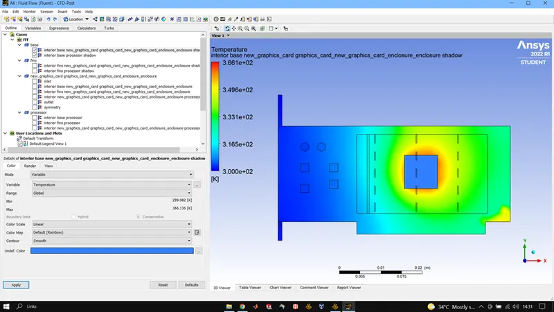
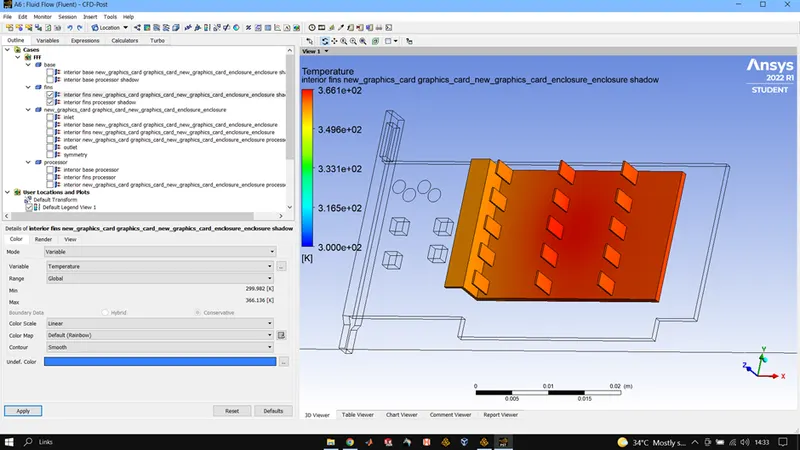
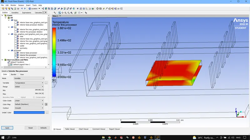
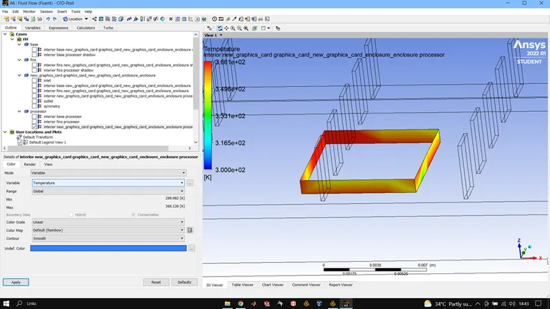
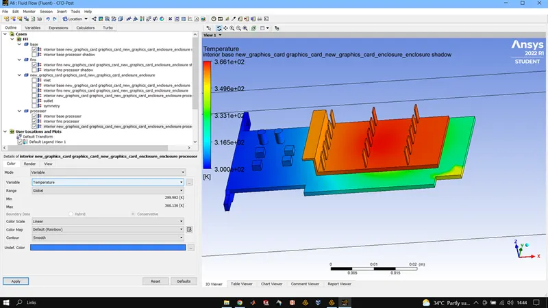
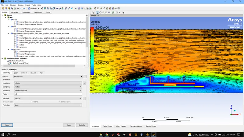
Maximum processor temperature is 366.24K and HTC max is -323.965 W/m2K
FOR V =3m/s
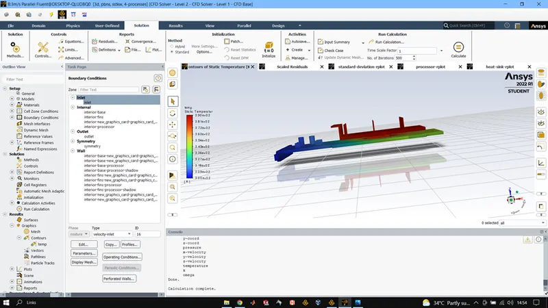
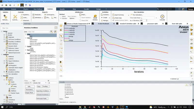
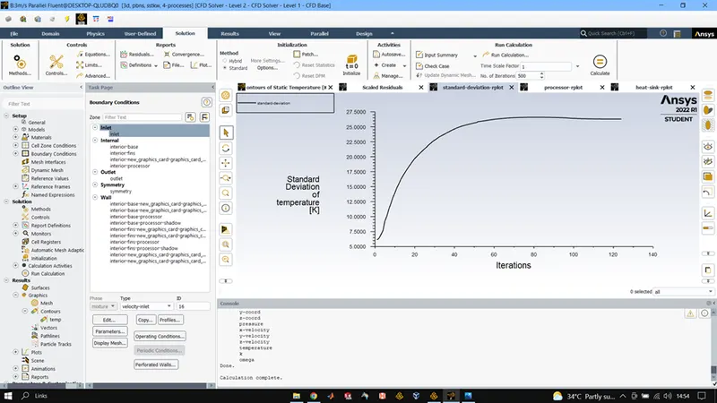
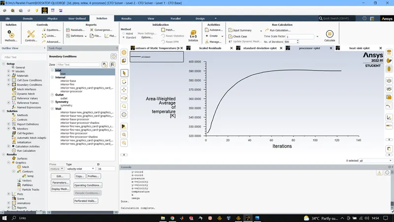
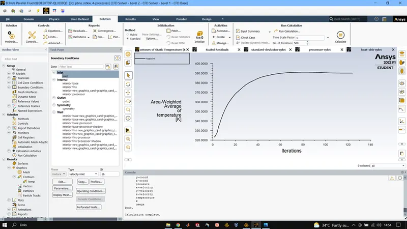
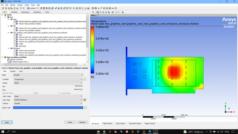
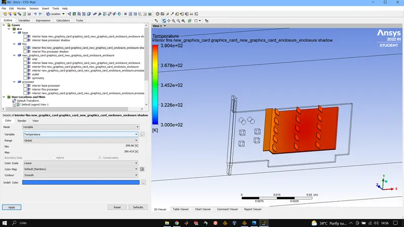
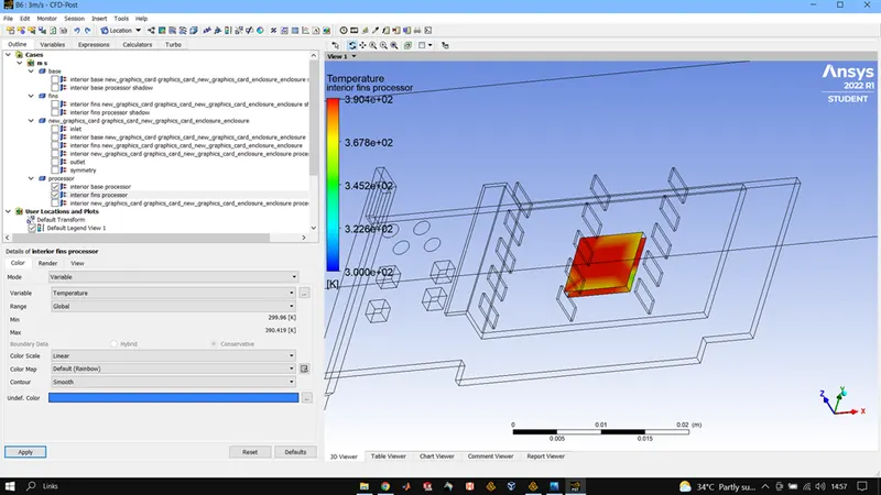
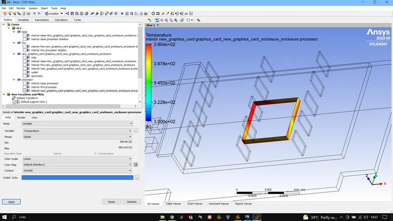
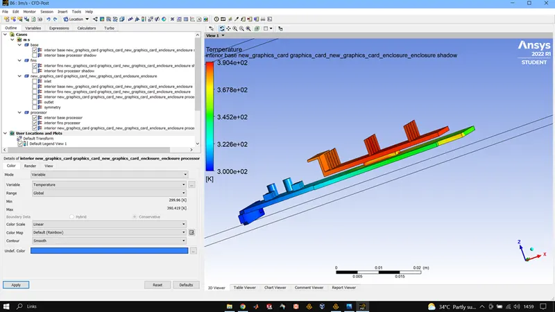
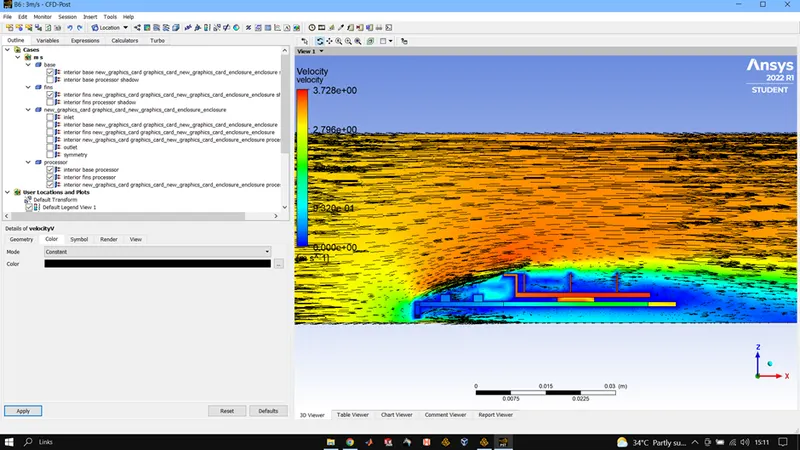
Maximum processor temperature is 390.53 K and HTC max is -232.65 W/m2K
FOR V = 1m/s
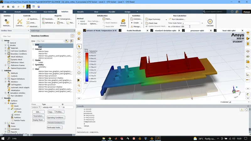
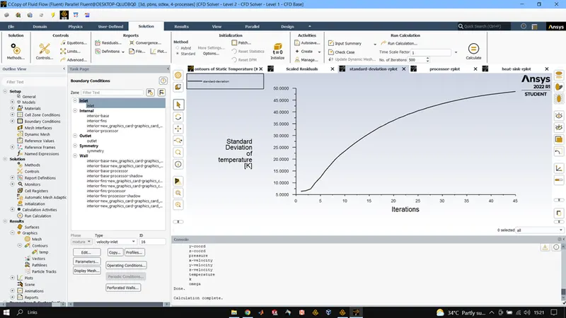
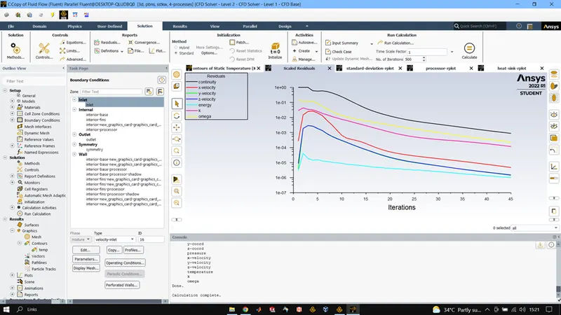
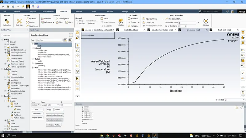
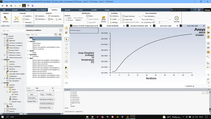
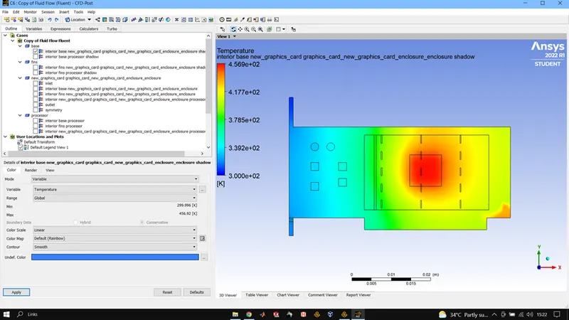
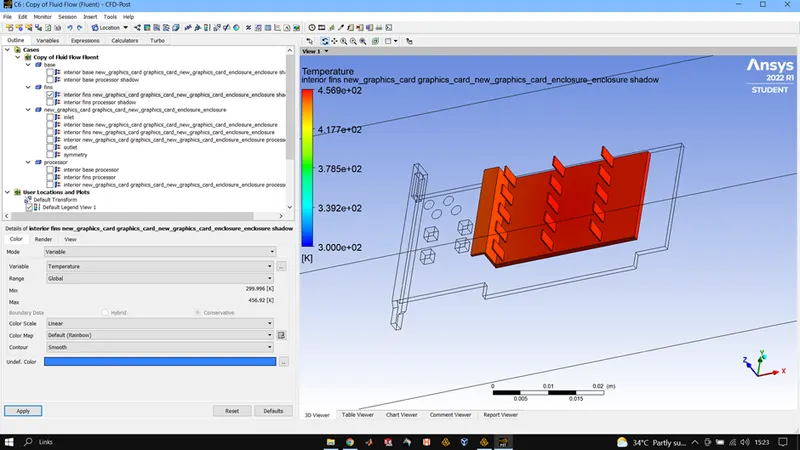
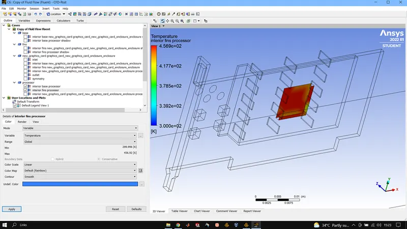
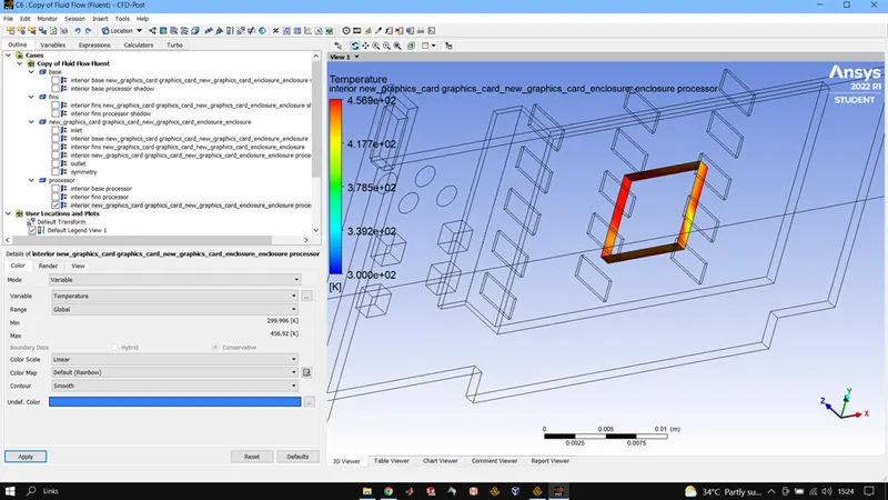
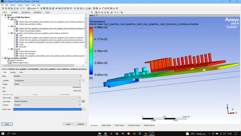
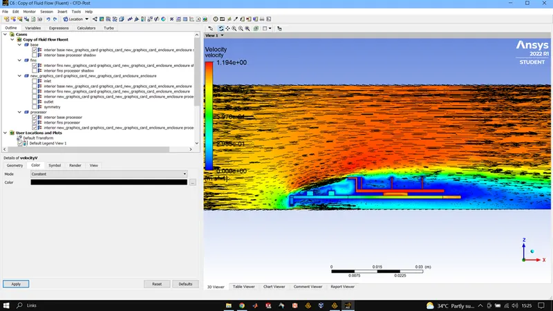
Maximum processor temperature is 457.030K and HTC max is -131.18 W/m2K
CONCLUION:
Convergence of the results can be seen from the residual plot where all the criteria related to flow field and energy equation are dropping continuously with no abnormality. Also, from plot of temperature of processor and fin we can see that they have attained steady state hence we can say our simulation has converged.
When we decreased the velocity of inlet air, we observe that temperature of processor increases which shows that a high velocity is required for temperature control of processor. This can be understood as with higher velocity the amount of heat transferred from processor to the air molecules increases as there would be a greater number of molecules taking up heat from processor in a given time frame compared to lower velocities.
We also observe that the velocity of air at outlet is higher than inlet this due to the increase in kinetic energy of air molecules due to heat absorption from the processor.