Week 6 - CHT Analysis on a Graphics card
Aim : To perform a steady-state conjugate heat transfer analysis on a model of a graphics card.
Objectives:
- Run the simulation by varying the velocity from 1m/sec to 5m/sec for at least 3 velocities and discuss the results.
- Find out the maximum temperature and heat transfer coefficient attained by the processor.
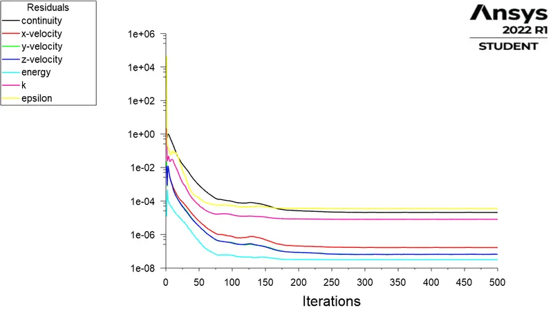
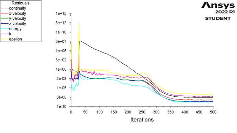
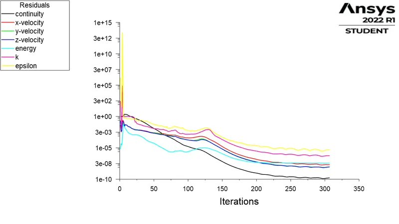
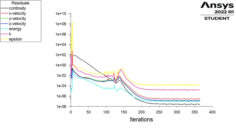
- Prove that the simulation has achieved convergence with appropriate images and plots.
- Identify potential hotspots on the model.
Modelling and Solving Approach :
A. Geometry
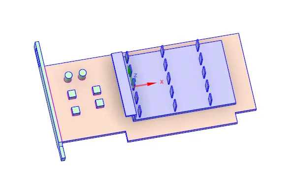
- Geometry was imported into the space claim.
- We need to check the interfaces of the geometry If there is Interfaces It will generates Non-confirmal meshes and It will lead to the wrong results.
- For the confirmal meshes We have to ON the Share-topology GO to workbench and select the Whole body and Click on the Shareprep then click on Ok.
- It will shows the pink Outlines on the Interfaces of the solid bodies It means the Interfaces of the solid bodes are shared.
B. Meshing
- Create named selection as Inlet, Outlet, Symmetry, Fins, Processor and Base.
- The file was initially meshed with base line mesh and further refined and the final refined mesh file was simulated for varying inlet velocity.
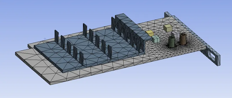
Mesh file 1
The body was meshed with default mesh.
No.of elements = 83537
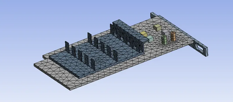
Mesh file 2
The element size is reduced to 5 mm and body sizing is given to enclosure with an element size of 2.5 mm.
No.of elements = 286401
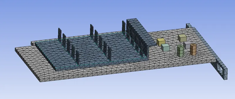
Mesh file 3
The previously meshed file was further given a body sizing of element size of 1.5mm on the fins to completely capture the conduction through the fin. Similarly body sizing of element size of 1.5mm is given to Processor and Base.
No.of elements = 313682
C. Fluent setup
- General
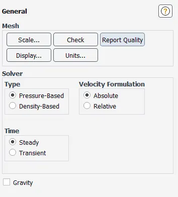
- The energy was turned on since it requires the calculation of temperature.

- Viscous model
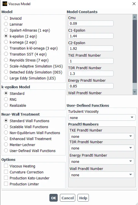
- Boundary conditions
Inlet velocity is vary from 1 m/s to 5 m/s and temperature is 300 K.
- Material selection and creation
Enclosure : Fluid Material - Air
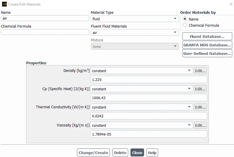
Processor : Solid material- Silicon
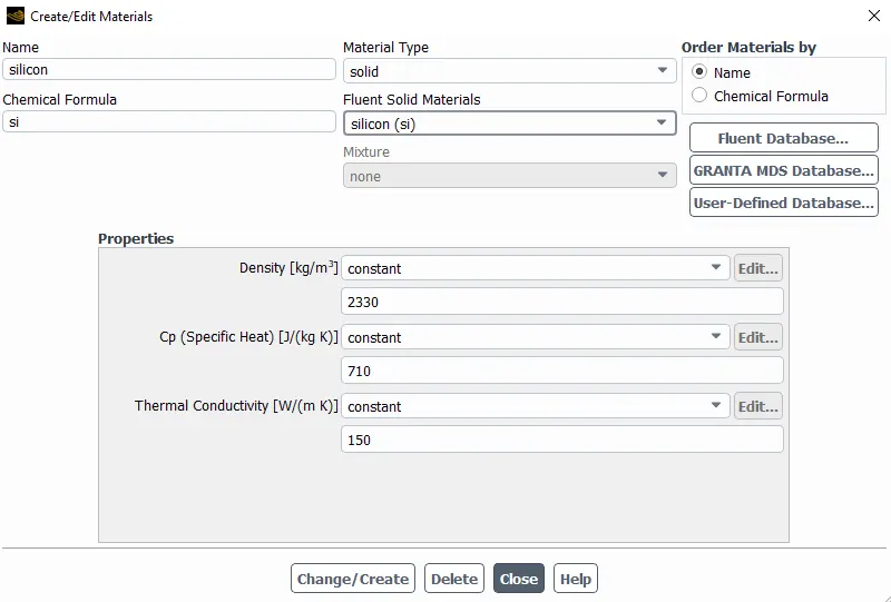
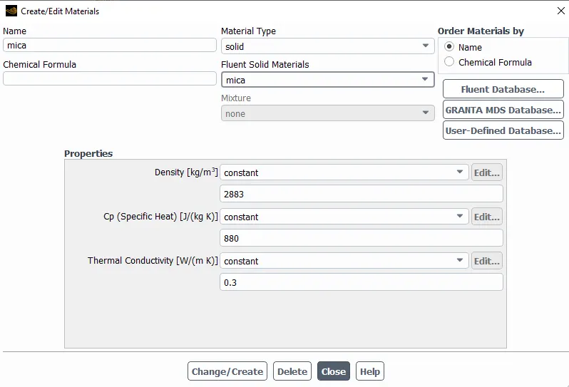
Base :
For base low thermal conductivity material is used.
Solid material- Mica
Fins :
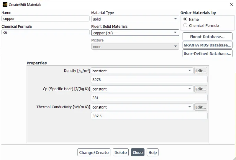
For fins high thermal conductivity material is used.
Solid material- Copper
- Cell zones
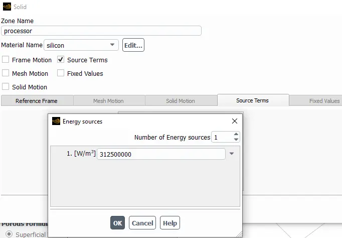
In the cell zone condition fluids and solid components were assigned and the processor was considered to be giving an output of 20W heat which computed a heat generation of
`(20 W)/(64xx10^9m^3) = 312500000W/m^3`
Materials Assigned :
| Sr/No. | Component | Material assigned |
| 1 | Processor | Silicon |
| 2 | Base | Mica |
| 3 | Fins | Copper |
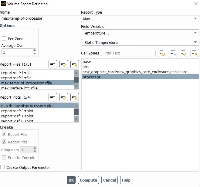
- Create report defination for Maximum temperature
- Create report defination for Maximum surface heat transfer coefficient.

- Create contours of temperature and velocity.
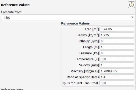
- Reference values
Results :
CASE 1 : Baseline setup
The body was meshed with default mesh.
Inlet velocity = 1 m/s
Residuals :
Maximum temperature attained by processor :
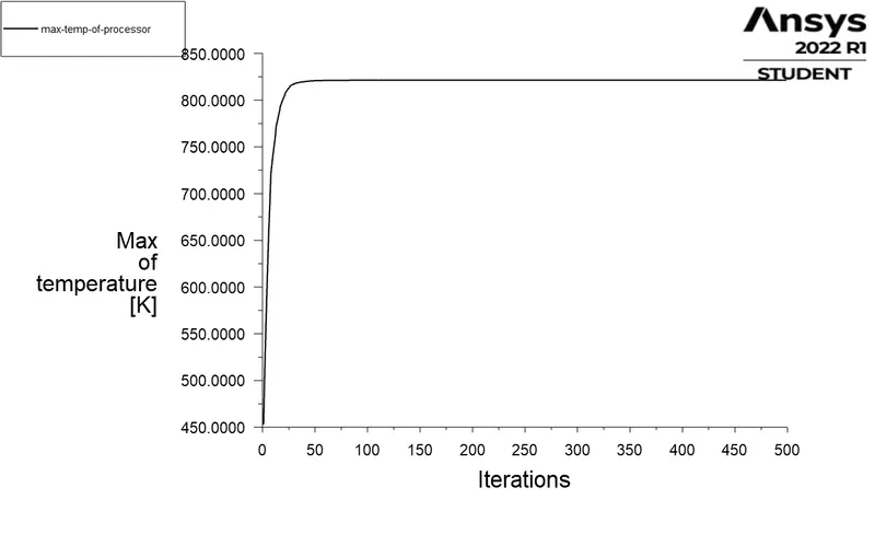
Maximum temperature attained by processor = 821.386 K
Maximum heat transfer coefficient attained by processor :
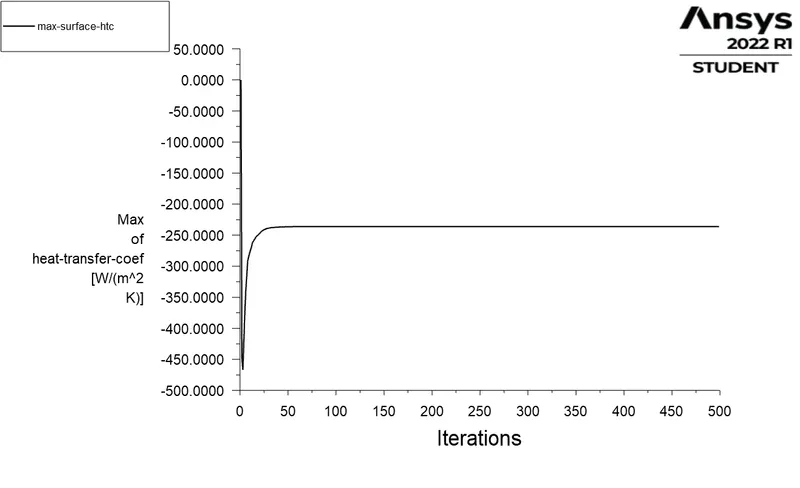
Maximum heat transfer coefficient attained by processor = -236.136 W/m^2K.
Negative sign of htc indicates that heat is removed from system.
Surface temperature contour :
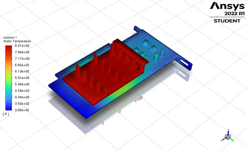
Temperature contour :
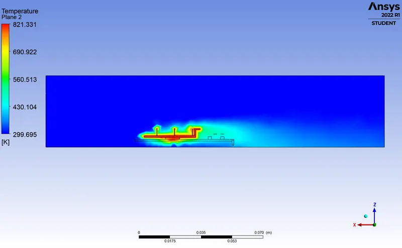
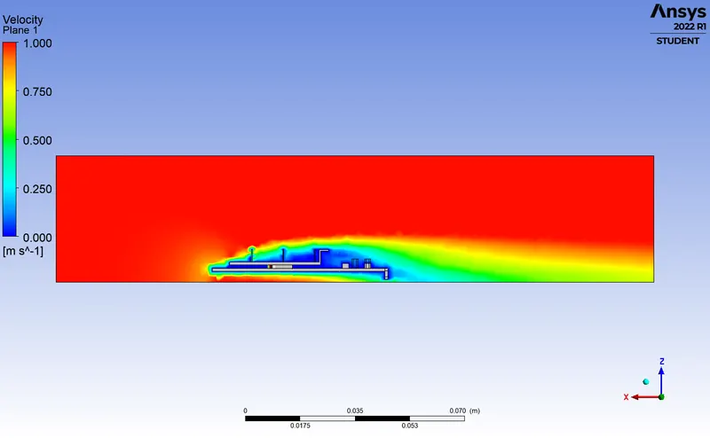
Velocity contour :
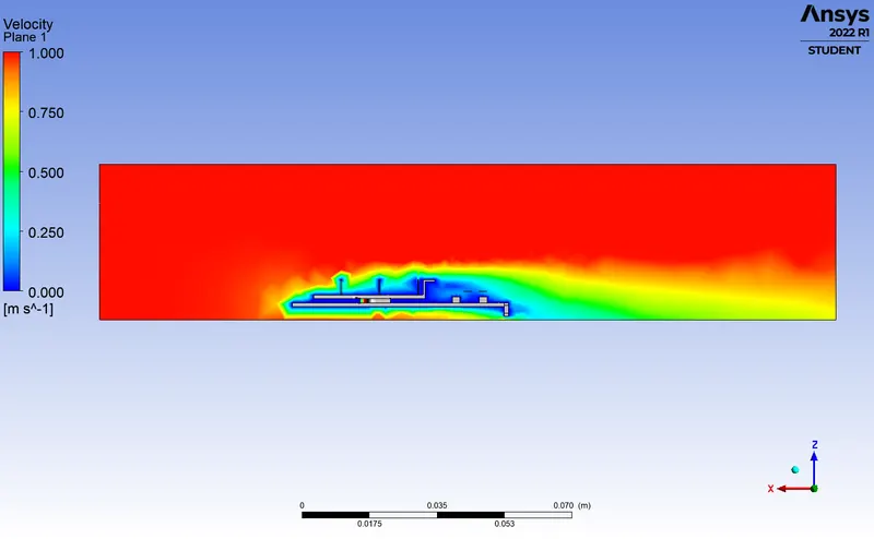
CASE 2 : Refined mesh.
The element size is reduced to 5 mm and body sizing is given to enclosure with an element size of 2.5 mm.
Inlet velocity = 1 m/s.
Residuals :
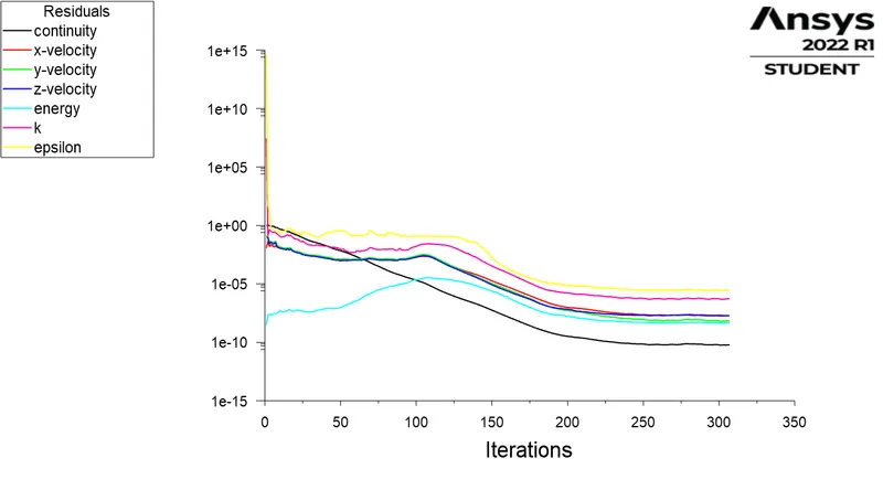
Maximum temperature attained by processor :
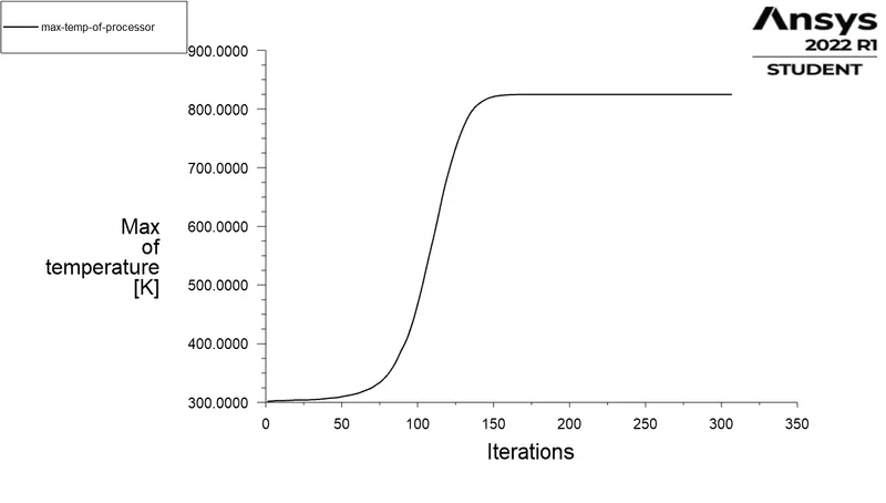
Maximum temperature attained by processor = 824.679 K
Maximum heat transfer coefficient attained by processor :
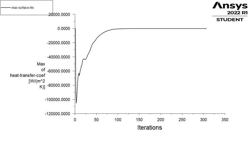
Maximum heat transfer coefficient attained by processor = -226.515 W/m^2K.
Negative sign of htc indicates that heat is removed from system.
Surface temperature contour :
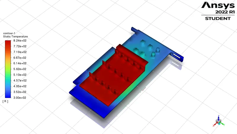
Temperature contour :
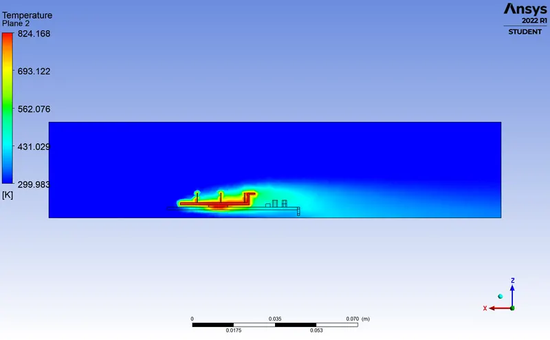
Velocity contour :
CASE 3 : Modification in refined mesh.
The previously meshed file was further given a body sizing of element size of 1.5mm on the fins to completely capture the conduction through the fin. Similarly body sizing of element size of 1.5mm is given to Processor and Base.
Inlet velocity = 1 m/s.
Residuals :
Maximum temperature attained by processor :
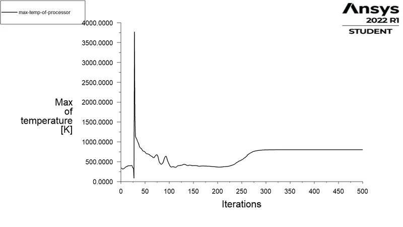
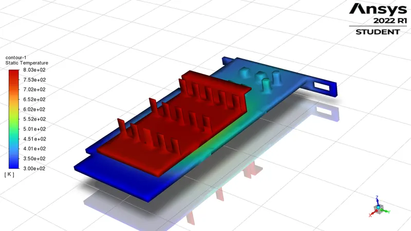
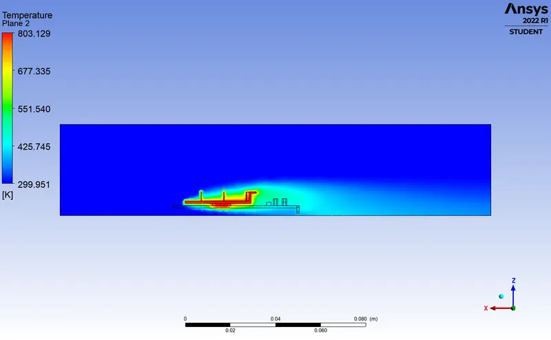
Maximum temperature attained by processor = 803.358 K
Maximum heat transfer coefficient attained by processor :
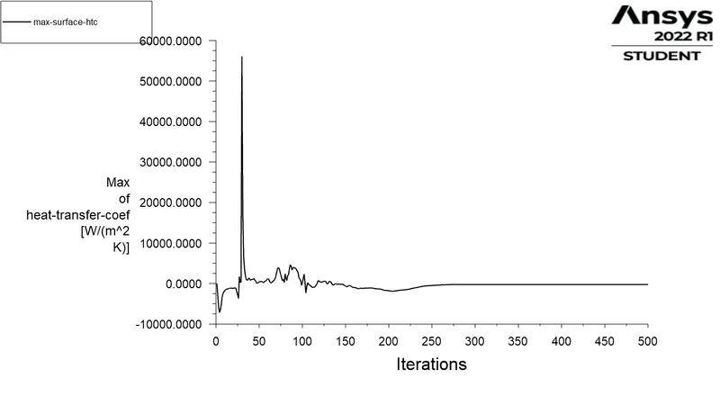
Maximum heat transfer coefficient attained by processor = -226.647 W/m^2K.
Negative sign of htc indicates that heat is removed from system.
Surface temperature contour :
Temperature contour :
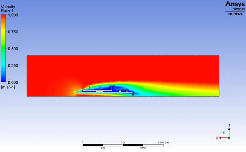
Velocity contour :
CASE 4 : Inlet velocity = 3 m/s.
Modified refined mesh is taken and inlet velocity of 3 m/s is set.
Residuals :
Maximum temperature attained by processor :
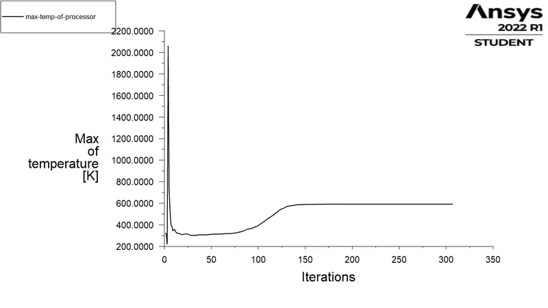
Maximum temperature attained by processor = 591.631 K
Maximum heat transfer coefficient attained by processor :
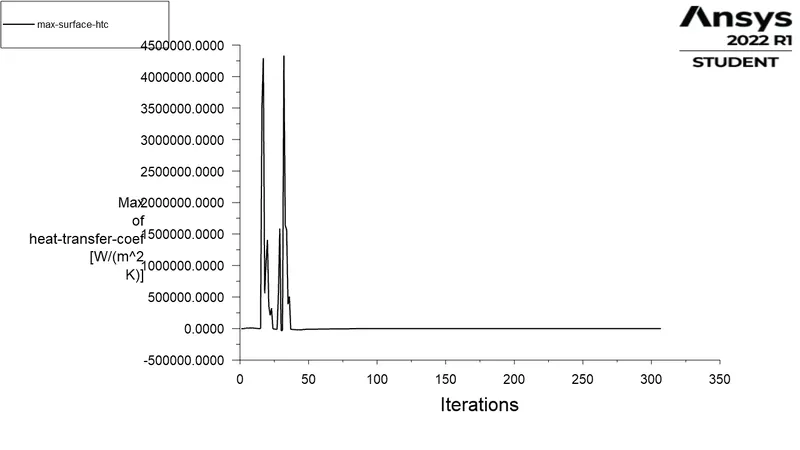
Maximum heat transfer coefficient attained by processor = -395.051 W/m^2K.
Negative sign of htc indicates that heat is removed from system.
Surface temperature contour :
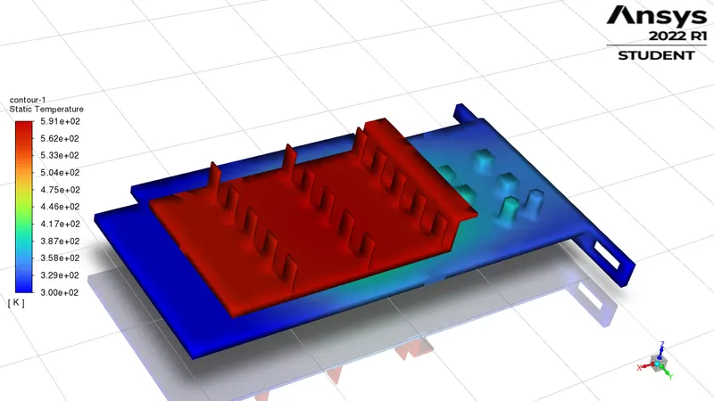
Temperature contour :
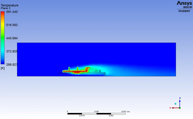
Velocity contour :
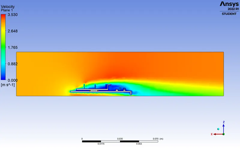
CASE 5 : Inlet velocity = 5 m/s.
Modified refined mesh is taken and inlet velocity of 5 m/s is set.
Residuals :
Maximum temperature attained by processor :
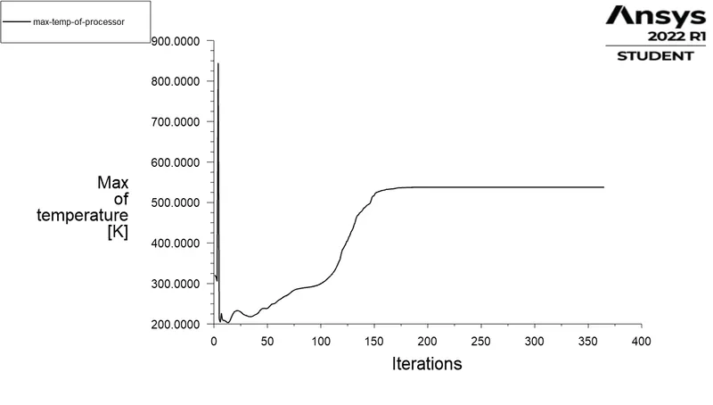
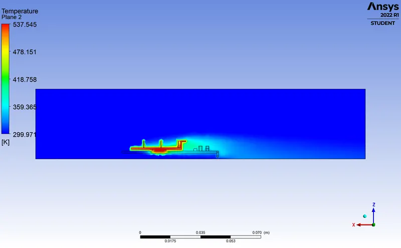
Maximum temperature attained by processor = 537.688 K
Maximum heat transfer coefficient attained by processor :
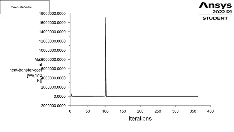
Maximum heat transfer coefficient attained by processor = -492.033 W/m^2K.
Negative sign of htc indicates that heat is removed from system.
Surface temperature contour :
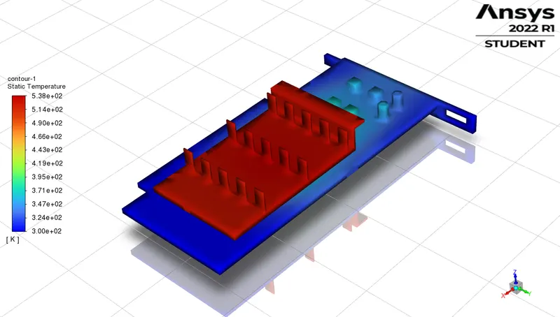
Temperature contour :
Velocity contour :
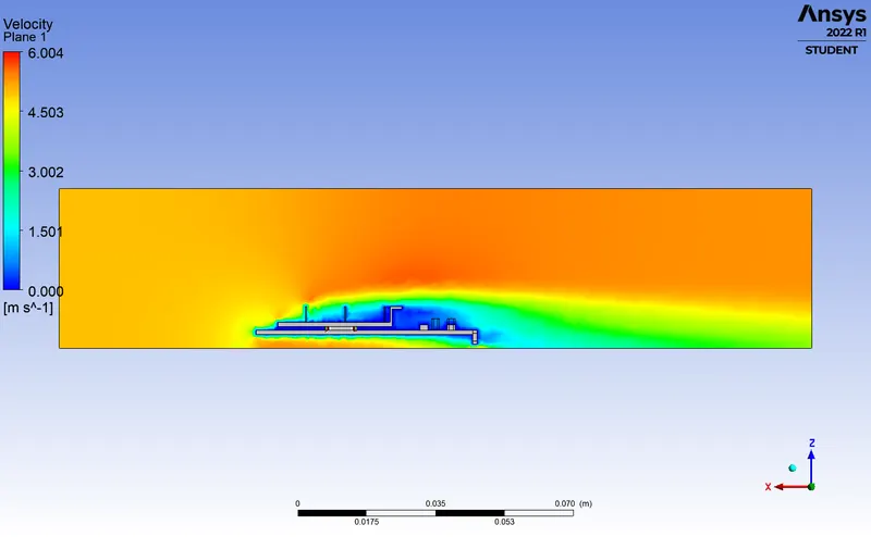
Comparison of velocity with temperature :
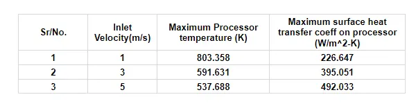
Mesh independent study :
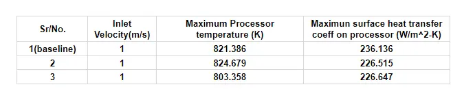
Further mesh independent study could not be carried out due to limitation of no. of elements in the student version.
Potential hotspots :
- Most of the heat are dissipated through the fin which helps to conserve the PCB from causing any heat damage. thus copper is best selected for fin as copper is a good conductor of heat and hence, it is distributing the heat properly to the overall surface area and providing a better heat dissipation effect with a higher heat transfer rate.
- Also the PCB material was selcted as mica which has a llow conductivity thus does not conduct the heat from the processor.
Conclusion :
- Refining mesh gives the best results thus the main heat dissipation being through the fins we refine the mesh at that region.
- Increasing velocity increases the convection as there occurs and increase in the Reynolds number. thus increasing the velocity of the fluid carries away most of the heat in the fins which cause the reason for decreasing surfce temperature and the avg outlet temperature with increasing velocity.
- Mesh/ grid dependency test is very important to get confidence over results.