Week 6 - CHT Analysis on a Graphics card
CHT ANALYSIS ON A GRAPHICS CARD
OBJECTIVE
In the challenge our objective is to perform a steady state simulation of a conjugate heat transfer in a graphics card.we will be running the simulation for deafault mesh and refined mesh .The air flow over the surface is varied from 1m/s to 5 m/s.
from this simulation we want to find, the hotspots and heat transfer co-efficient for the heat transfer process.
INTRODUCTION
graphics card (also called a video card,display card ,graphics adaptor, or display adaptor) is an expansion card which generates afeed of output images to a display device (such asa computer monitor). These graphics card generates heat when under operation.The graphics card generates heat while under operation.thus heat is mostly generated in the processor. The heat generated must be removed from the processor. From this purpose heat sink is provided .A heat sink is mounted on most modern graphics cards. Aheat sink spreads out the heat produced by the graphics processing unit evenly throughout the heat sink and unit itself. The heat sink commonly has a mounted aswell to cooltheheatsink and graphicsprocessing unit. The heat sink is mostly fins made of aluminium.These increase the het transfer area and hence helps inheat transfer process fans are employed to increase the heat transfer co-efficient . The entire set up is arranged onpc made up of fiber glass. The processor is made of silicon material we will be using the followingmaterial for our simulation.

STEPS FOLLOWED
1. Geometry preparation
b) Meshing
c) set up
d) Results
a) Geometry preparation
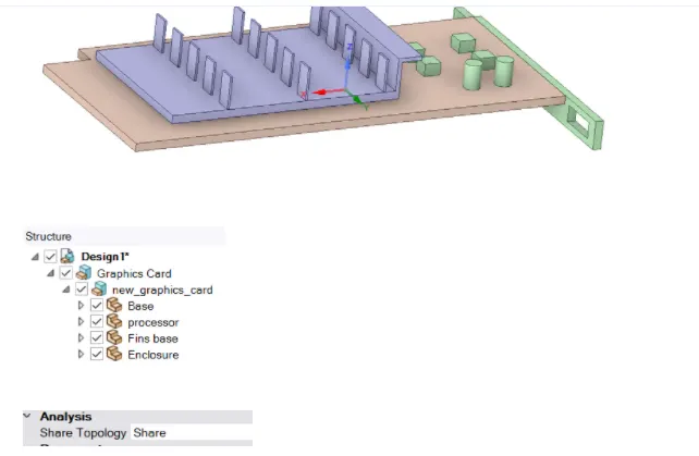
Already available model of graphics card used for the simulation.In space claim the model was imported.
b)
Meshing
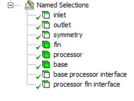
creating name selection
Basic mesh
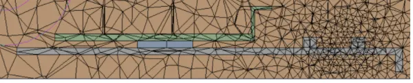

The mesh is conformal
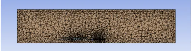
refined mesh

c)set up
In set up
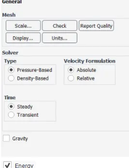
select pressure based steady state solver.
Energy equation is enabled.
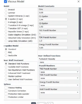
K-epsilon standard model
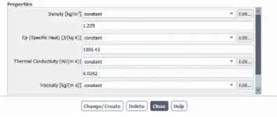
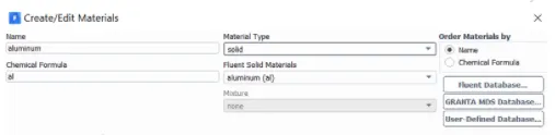
In material use air and aluminium create new material which are not present in the data base for base and processor.
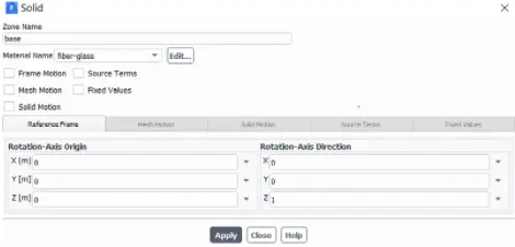
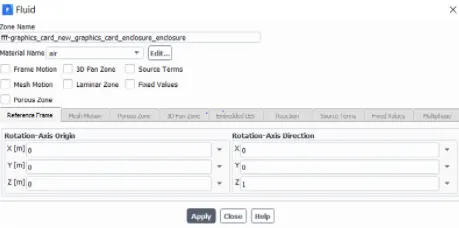
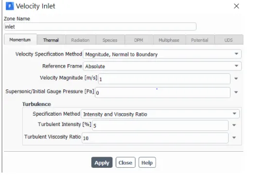
Give appropriate condition for cell zones and boundary condition.
in solution
select hybrid initialization and initialize the solution.
In Result
create planes and contours
in solution
create animation
material

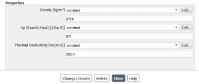

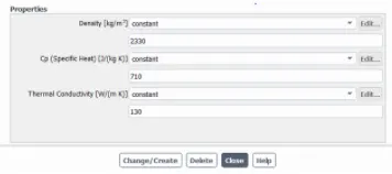
cell zones
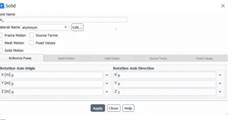
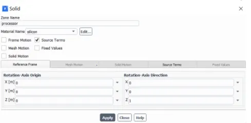
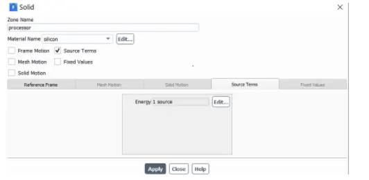
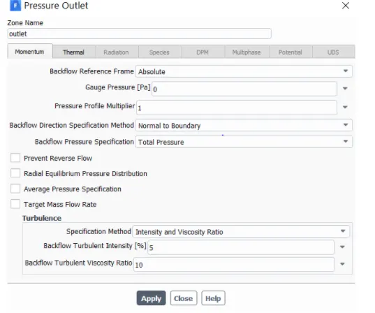
BOUNDARY CONDITION

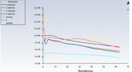
RESULT
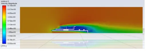
For coursemesh with 1m/s velocity input.
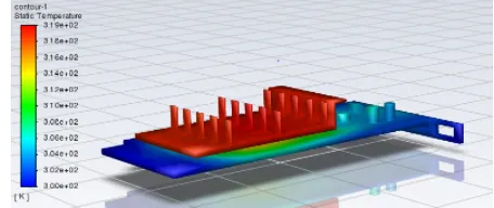
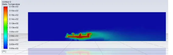
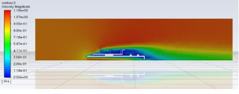
refined mesh with 3m/s
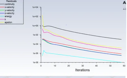
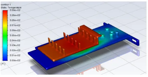
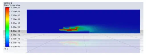
conclusion
The following results obtained
inlet velocity Maximum temperature
1m/sec(basic mesh) 319.5183
1m/sec(refined mesh) 317.0809
3m/sec(Refined mesh) 309.3875
5m/sec(Refined Mesh) 307.3508
The maximum temperature keeps decreasing with increase in heat transfer co-efficient.
The maximum temperature(hotspot) always occur inside the processor because it is the volume where heat is generated.